


SparkFun Pro nRF52840 Mini Library for Proteus: BLE Simulation


Hello friends, I hope you all are doing great. Today, I am going to share the SparkFun Pro nRF52840 Mini Library for Proteus, so you can run a Bluetooth LE simulation of SparkFun's Pro nRF52840 Mini. It is a compact red board with a Raytac MDBT50Q module, a LiPo charger, a Qwiic socket for I2C sensors and a row of ground pads beside every header. Our part is drawn at true scale from SparkFun's own board file, and it runs your Arduino sketch in Proteus 8.5 with Bluetooth LE to a phone.
SparkFun Pro nRF52840 Mini Library for Proteus
Latest version: V1.0 (November 2026, this tutorial)
Helping Tools
- Laptop WiFi Monitor: a laptop on the Wi-Fi of your design: a browser, a TCP / UDP terminal and ping
- Mobile WiFi Monitor: a smartphone that opens the pages of your board and sends it commands
- Serial Monitor Advance: a serial terminal window for the UART of your board
For the demo we built a Bluetooth desk lamp dimmer: a knob sets the brightness of a white LED, a button switches it on and off, and a phone follows every change.
NOTICE: Proteus has no nRF52840 model, so our team has put a lot of effort into building this board ourselves: the pins, the LEDs, the button and Bluetooth LE to the phone are all our own model, and your sketch compiles with our free TEP Boards for Proteus add-on. Your feedback is the fuel that keeps us going, so please tell us what you think in the comments below. And if our free libraries help you, you can buy us a coffee. So, let's get started with the SparkFun Pro nRF52840 Mini Library for Proteus:
What is the SparkFun Pro nRF52840 Mini?
The Pro nRF52840 Mini (DEV-15025) is SparkFun's small development board for the nRF52840, built around a Raytac MDBT50Q module (an Arm Cortex-M4F at 64 MHz, 1 MB of flash, 256 KB of RAM, Bluetooth LE and native USB) with its antenna at one end. It adds what a portable project needs: a LiPo charger with a JST socket, an ON/OFF switch, a Qwiic socket for SparkFun's I2C modules, and a ground pad next to every signal pad.
| Part | The real board | In the library |
|---|---|---|
| Module | Raytac MDBT50Q with the nRF52840 | your Arduino sketch, ArduinoBLE |
| Size | 46.99 x 22.86 mm | drawn at true scale |
| Pin numbers | Arduino pin n = P0.n | the same numbers |
| Analog | A0 to A7 on pins 2, 3, 4, 5, 28, 29, 30, 31 | analogRead 0 to 1023 |
| LEDs | blue on P0.07, red power, yellow charge | the blue one programmable |
| Buttons | RESET, BOOTLOAD on P0.13 | both clickable |
| Qwiic | SDA P0.08, SCL P0.11 | SDA and SCL pins on the part |
Drawn from SparkFun's Own Board File
SparkFun publishes the board's design files. We read the pins straight from them: the top row from the USB end is VIN, GND, RST, 3V3, 4, 5, 28, 29, 30, 31, 3 and 2; the bottom row is 17 and 15, the Qwiic socket, then 19, 20, 21, 22, 23, 9 and 10. The buttons, the switch, the LEDs, the debug header and the module sit where the real board has them.
Pin Numbers = Port Numbers
SparkFun's Arduino core uses a simple rule: Arduino pin n is the chip's P0.n. Pin 19 is P0.19, pin 7 is P0.07. That makes the datasheet and the code easy to compare, but it also means the analog inputs have numbers like 2, 3 and 28 - analogRead(A0) reads pin 2, not pin 0. Our library keeps SparkFun's numbers.
Features of the SparkFun Pro nRF52840 Mini Library for Proteus
- The board at true scale: the red PCB, the micro-USB, the JST socket, RESET, the ON/OFF switch, BOOTLOAD, the three LEDs, the Qwiic socket, the debug header, the MDBT50Q and the pin rows with their ground pads, with our small TEP signature.
- Your sketch: a .hex for "SparkFun Pro nRF52840 Mini (TEP Proteus)" with SparkFun's pin numbers.
- Bluetooth LE: ArduinoBLE with services, characteristics, descriptors and notifications; our Mobile WiFi Monitor is the phone.
- I2C on the Qwiic socket: SDA and SCL are pins of the part.
- A complete package: about 4.4 MB with the part, the add-on, the potentiometer, the LED, the resistor, the phone and the demo, without the source code of the models.
The Pro nRF52840 Mini in Proteus Simulation
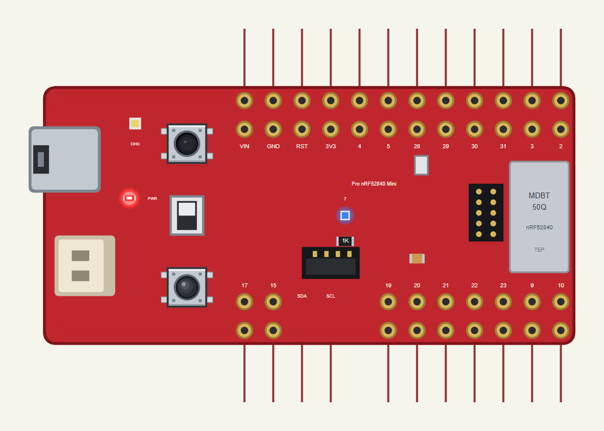
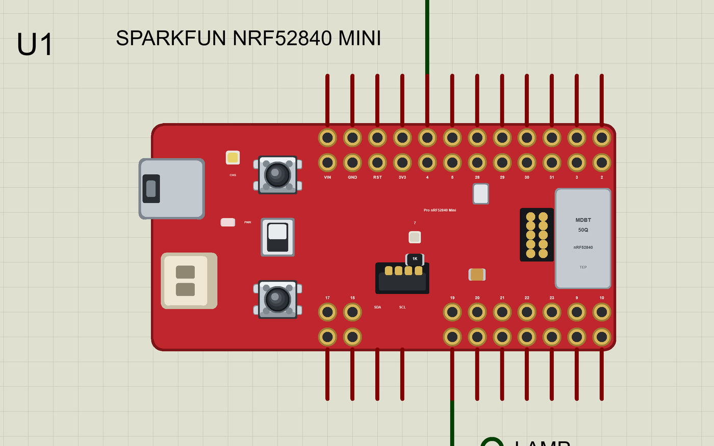
Search SPARKFUN in Pick Devices; the device SPARKFUN NRF52840 MINI is in TEPSFMINI52.LIB (Microprocessor ICs, Bluetooth Boards), with the prefix U. The micro-USB opens the serial monitor.
The Pins
| Pins | What the library does with them |
|---|---|
| 2, 3, 4, 5, 28 to 31 | A0 to A7: analogRead 0 to 1023 for 0 to 3.3 V, or GPIO and PWM |
| 17, 15 | Serial1 TX and RX, or GPIO |
| 19 to 23, 9, 10 | GPIO, PWM, interrupt, pulse timing |
| SDA, SCL | Wire on the Qwiic socket (pins 8, 11) |
| 7, 13 | the blue LED (lit when HIGH) and BOOTLOAD (LOW when pressed), on the board |
Download SparkFun Pro nRF52840 Mini Library for Proteus
Click the button below to download SparkFun-Pro-nRF52840-Mini-Library-for-Proteus-v1.0.zip (about 4.4 MB, without the source code of the models):
SparkFun Pro nRF52840 Mini Library for Proteus V1.0- README.txt: installation, the demo, the pins, the properties, troubleshooting and the limits.
- Proteus Library Files:
TEPSFMINI52.LIB, the potentiometer, the LED and the resistor (TEPPOT.LIB,TEPLED5MM.LIB,TEPRESISTOR.LIB) and the phone and laptop. - Proteus Model Files:
TEPNET.DLL,TEPPOT.DLL,TEPLED5MM.DLLandTEPRESISTOR.DLL. - Arduino Code: the demo sketch and the TEP Boards for Proteus add-on 1.93.0, with ArduinoBLE.
- Proteus Simulation: the demo project, its HEX file and copies of the DLLs.
No Proteus yet? Read How to Download and Install Proteus 7 and 8. New to libraries? Follow How to Install a New Library in Proteus.
How to Install SparkFun Pro nRF52840 Mini Library for Proteus
- Close Proteus and extract the whole zip file, for example to your Desktop.
- Copy the files from Proteus Library Files into the LIBRARY folder of Proteus.
- Copy the DLLs from Proteus Model Files into the MODELS folder, replacing an older
TEPNET.DLL. - Delete
TEPSFMINI52.IDXfrom the LIBRARY folder if it is there. - For your own sketches, copy Arduino Code\TEP Boards for Proteus\hardware into your Arduino sketchbook (Documents\Arduino) and restart the Arduino IDE; the board is SparkFun Pro nRF52840 Mini (TEP Proteus).
- Start Proteus, press P and search for SPARKFUN.
Demo: a Bluetooth Lamp Dimmer in Simulation
A dimmable lamp with a real knob is still the nicest way to set the light - and a phone that shows the level is handy for automation and for checking from the sofa whether the lamp in the workshop is still on.
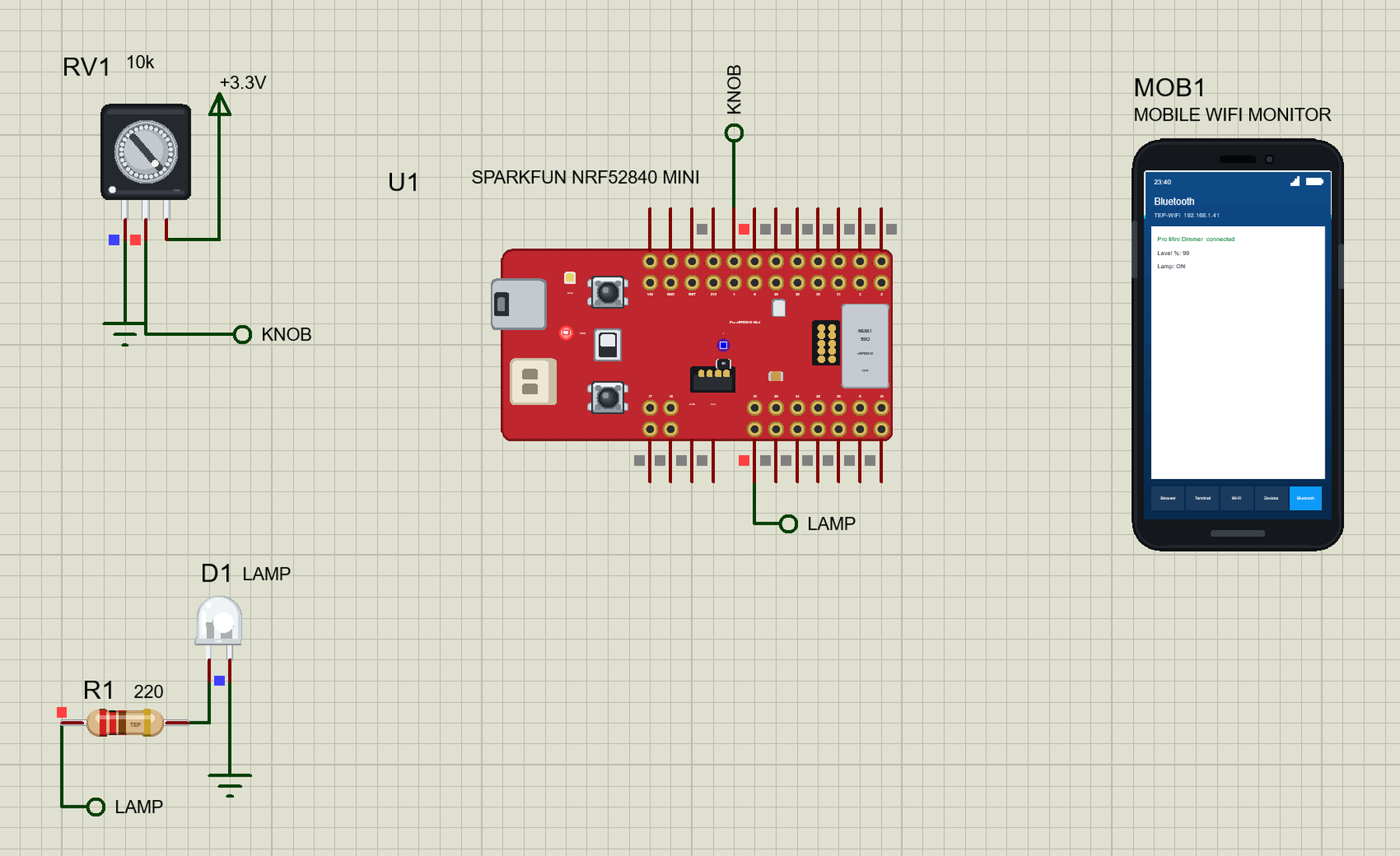
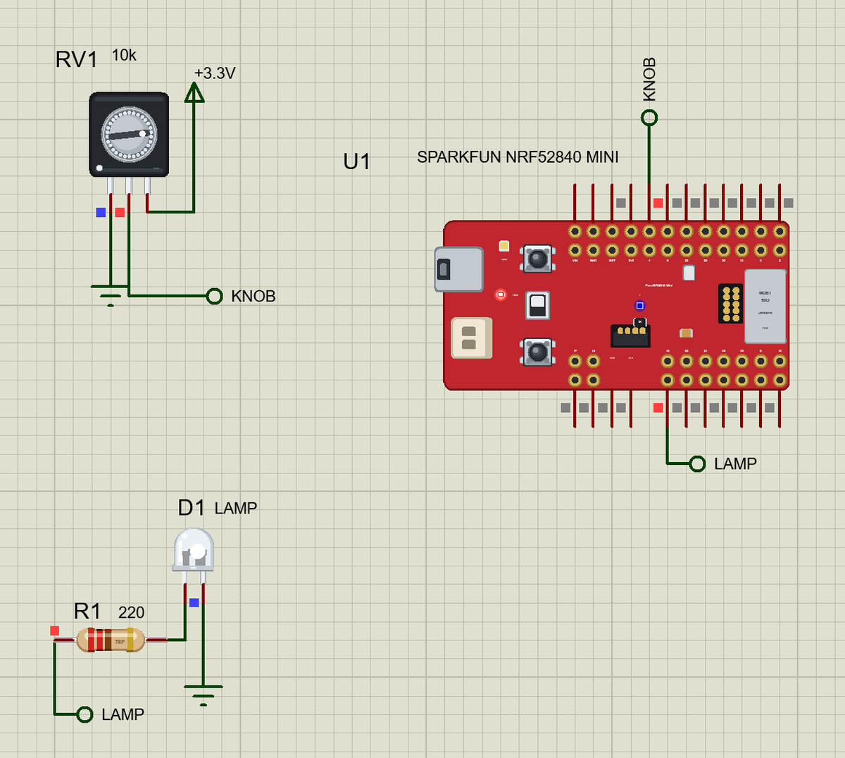
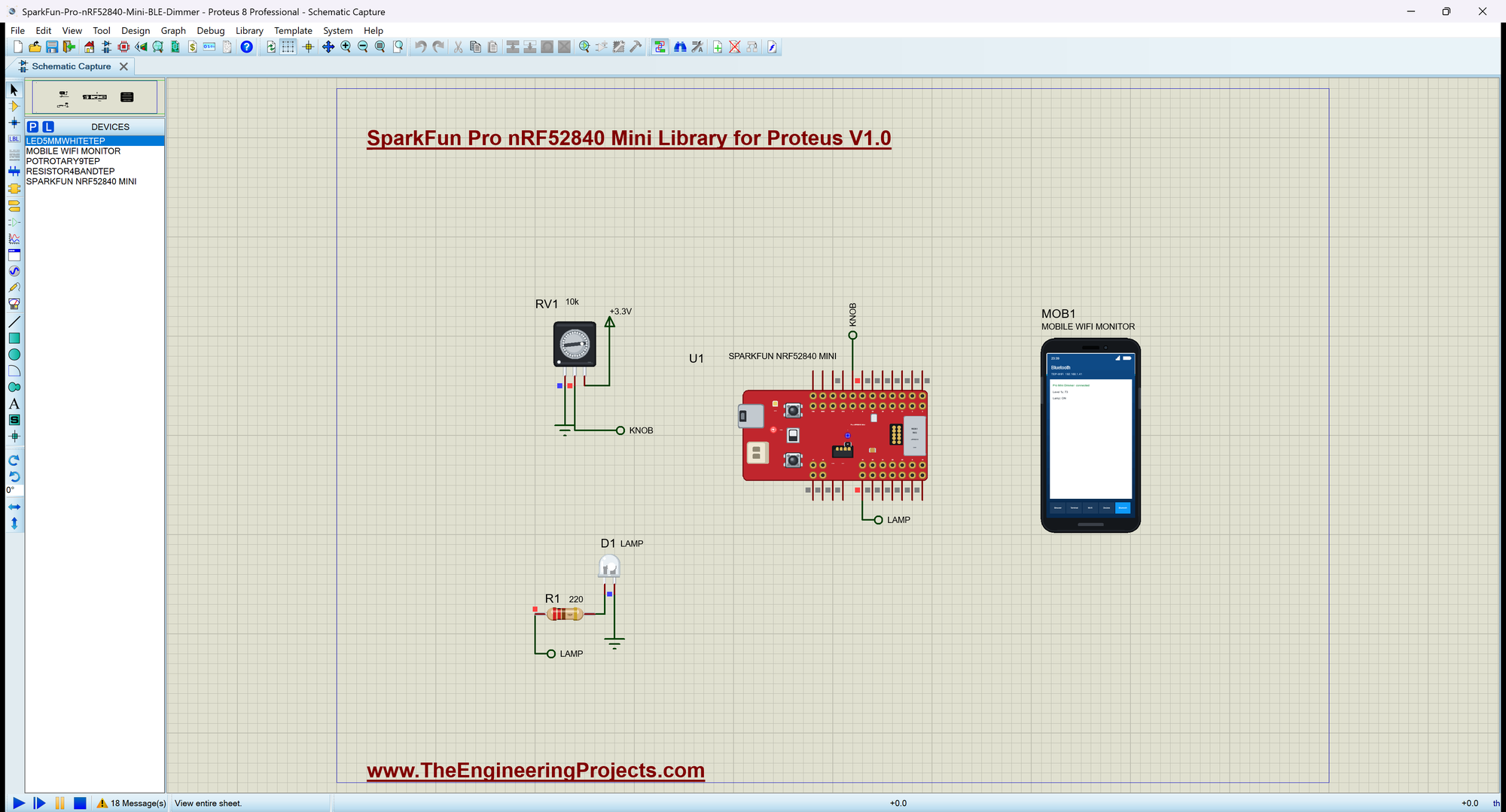
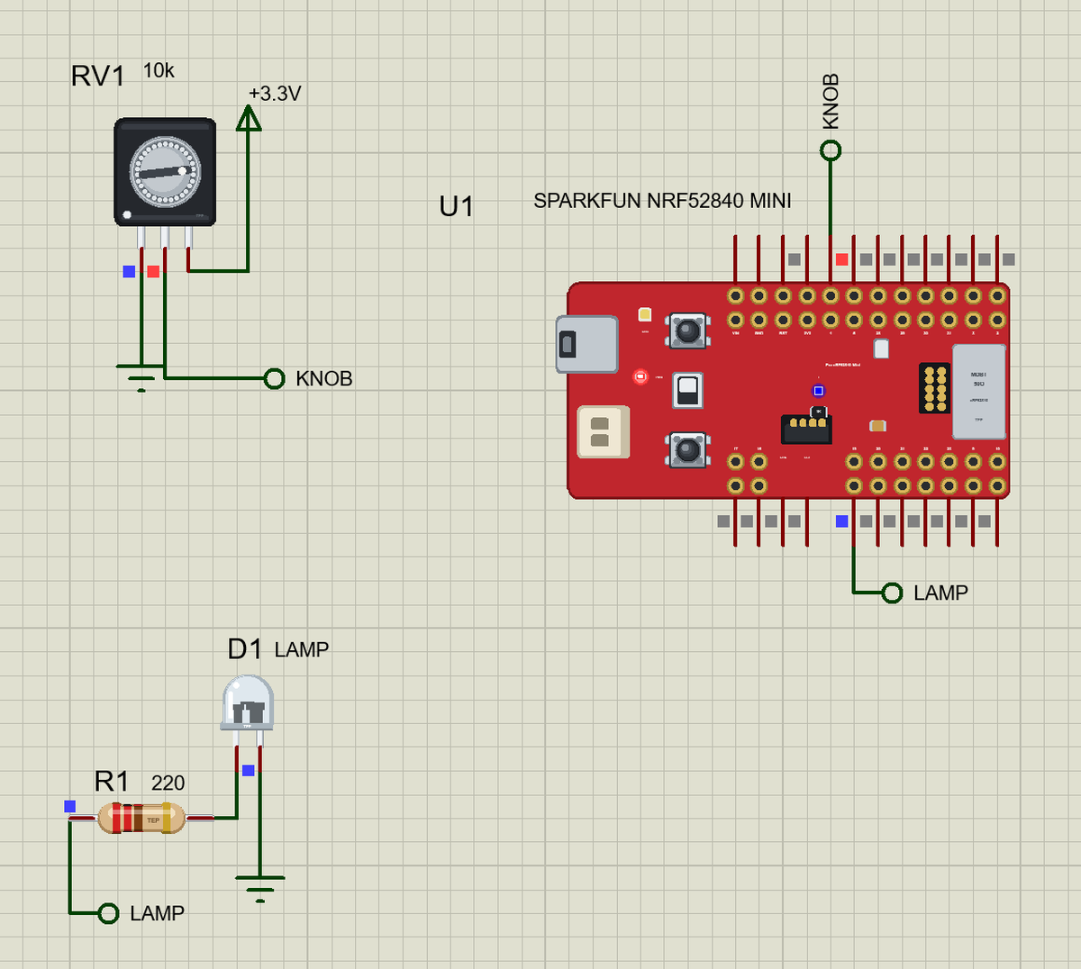
Open SparkFun-Pro-nRF52840-Mini-BLE-Dimmer.pdsprj. U1 runs SFMini52_BLE_Dimmer.hex; RV1 is a 9 mm pot from our Potentiometer Library for Proteus - pin 1 to ground, pin 3 to +3.3V, the wiper on A2 (pin 4); D1 is a white LED from our 5mm LED Library for Proteus, the lamp, through R1 (220 ohm) on pin 19; MOB1 is the phone.
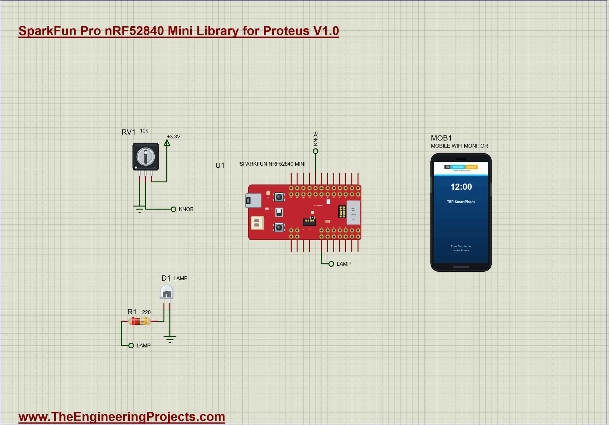
| What | Meaning |
|---|---|
| the knob | 0 to 100 % brightness |
| the lamp | PWM with a gamma curve |
| BOOTLOAD | the lamp on / off (the level stays) |
| the blue LED | a phone is connected |
| the phone | the level and ON / OFF, with notifications |
The Bluetooth Service
Two characteristics carry the level in percent and the lamp's state, each with a readable 0x2901 name:
BLEService lampService("19B100D0-E8F2-537E-4F6C-D104768A1214");
BLEIntCharacteristic levelChar("19B100D1-E8F2-537E-4F6C-D104768A1214", BLERead | BLENotify);
BLEStringCharacteristic stateChar("19B100D2-E8F2-537E-4F6C-D104768A1214", BLERead | BLENotify, 8);
BLEDescriptor levelLabel("2901", "Level %");
BLEDescriptor stateLabel("2901", "Lamp");
Reading the Knob
readKnob() runs ten times a second. A light filter smooths the reading, and the phone hears only about changes of 2 % or more - so the noise of a real pot does not flood the radio:
void readKnob() {                                           // 10 times a second: the knob, smoothed, in percent
  static long avg = -1;
  const int raw = analogRead(KNOB);                         // 0 .. 1023
  avg = avg < 0 ? raw * 16L : avg + raw - avg / 16;         // a light filter: 1/16 of each new reading
  const int percent = (int)((avg / 16) * 100L / 1023L);
  if (percent == level) return;
  level = percent;
  applyLamp();
  if (abs(level - shown) >= 2 || level == 0 || level == 100) {   // tell the phone about real changes, not the jitter
    shown = level;
    levelChar.writeValue(level);
    Serial.print(F(">> LEVEL ")); Serial.print(level); Serial.println(F(" %"));
  }
}
A Gamma Curve
Our eyes see brightness on a curve: 50 % PWM looks much brighter than half. gamma8() squares the level, so each step of the knob looks like the same step of light:
byte gamma8(int percent) {                                  // perceived brightness: a square law makes the knob feel even
  const long p = constrain(percent, 0, 100);
  return (byte)(p * p * 255L / 10000L);
}
On and Off
BOOTLOAD switches the lamp; the knob keeps its level for the next time:
void readButton() {                                         // BOOTLOAD: the lamp on / off
  const bool now = digitalRead(PIN_BUTTON1);
  if (now == lastButton) return;
  lastButton = now;
  if (now != LOW) return;
  on = !on;
  applyLamp();
  stateChar.writeValue(on ? "ON" : "OFF");
  Serial.println(on ? F(">> BUTTON: the lamp ON") : F(">> BUTTON: the lamp OFF"));
}
Run the Simulation
Press Run. The serial monitor - the same window as our TEP Serial Monitor Advance for Proteus - shows the name the board advertises and the knob's level:
SparkFun Pro nRF52840 Mini Bluetooth Dimmer - The Engineering Projects
Advertising as "Pro Mini Dimmer"   the knob on A2, BOOTLOAD = on / off
>> LEVEL 49 %
Lamp: ON, level 49 %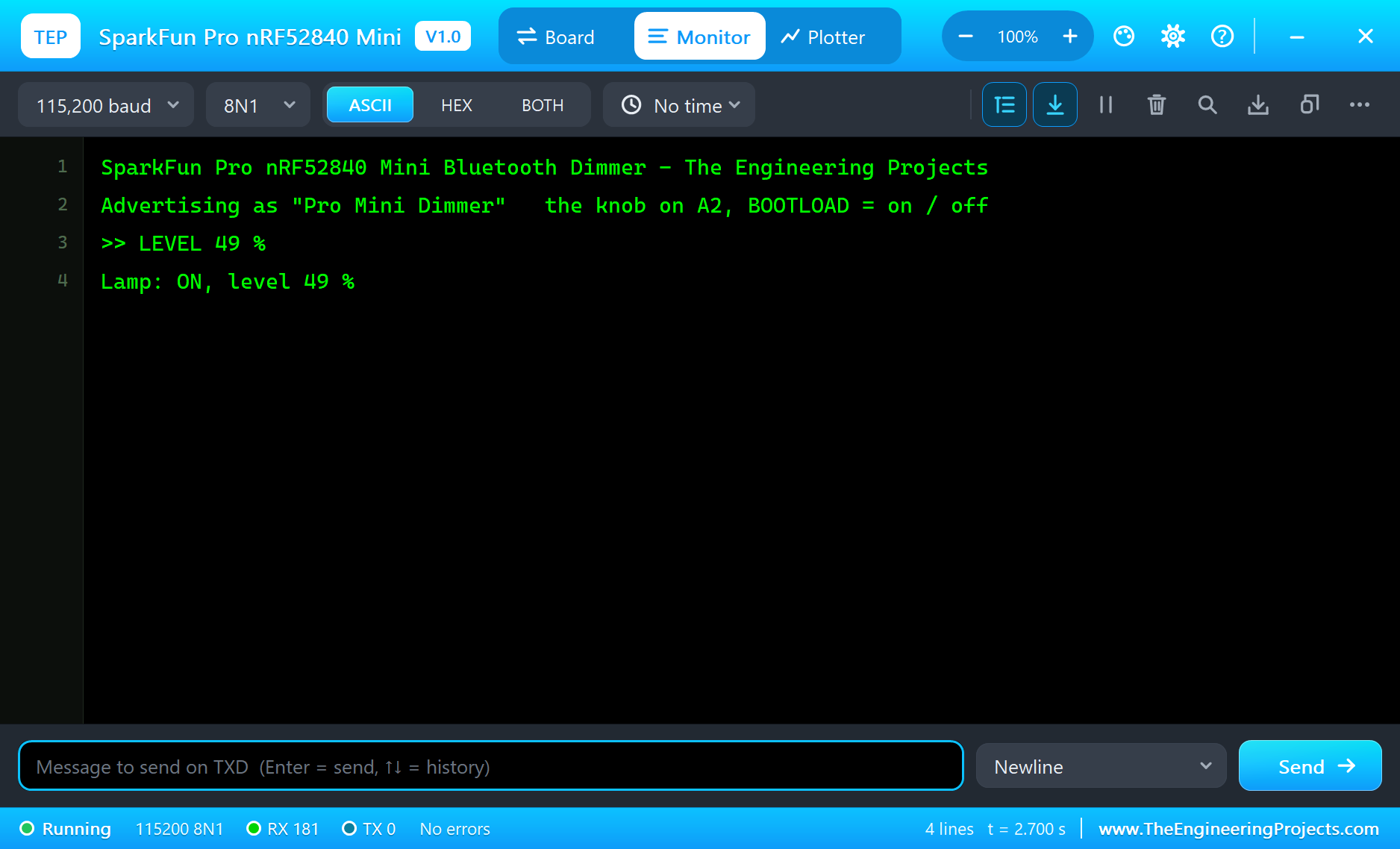
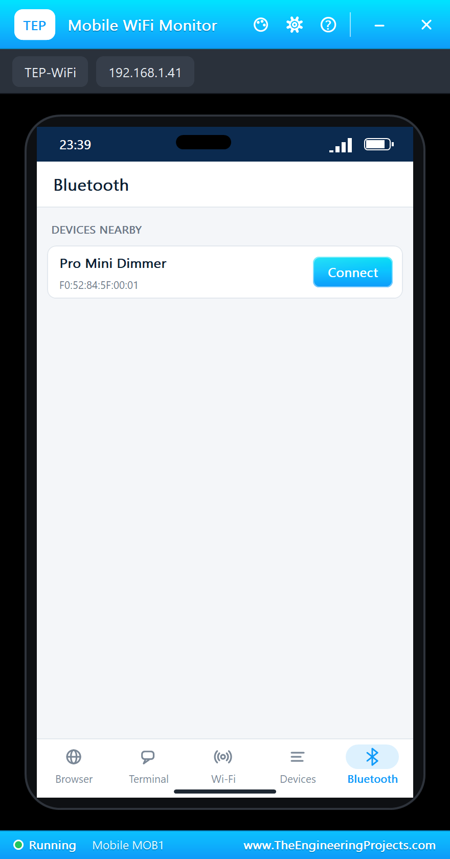
Connect the Phone
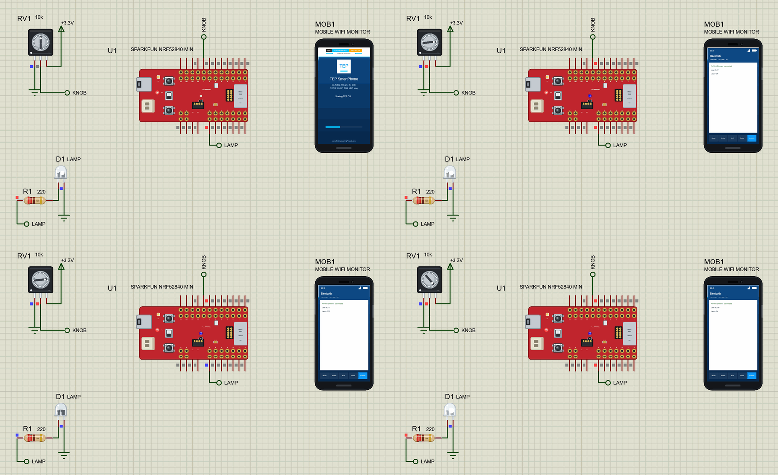
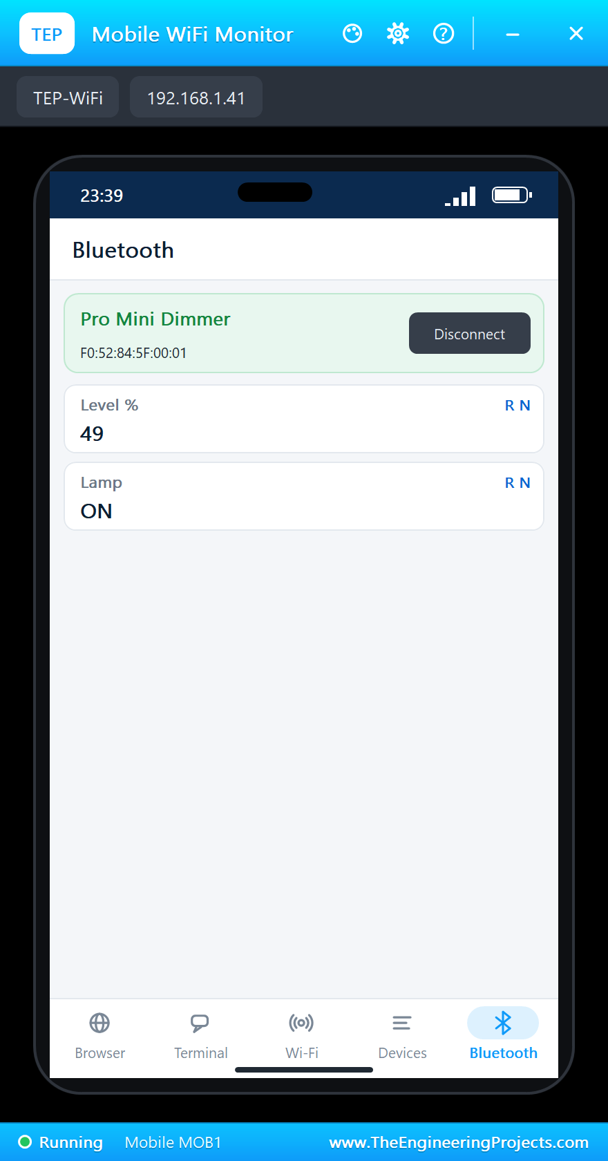
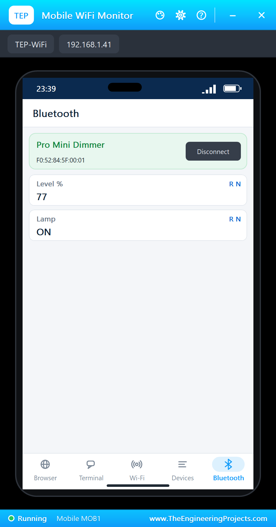
On the phone open the Bluetooth app, press SCAN and connect to "Pro Mini Dimmer" - the blue LED lights:
Turn the Knob
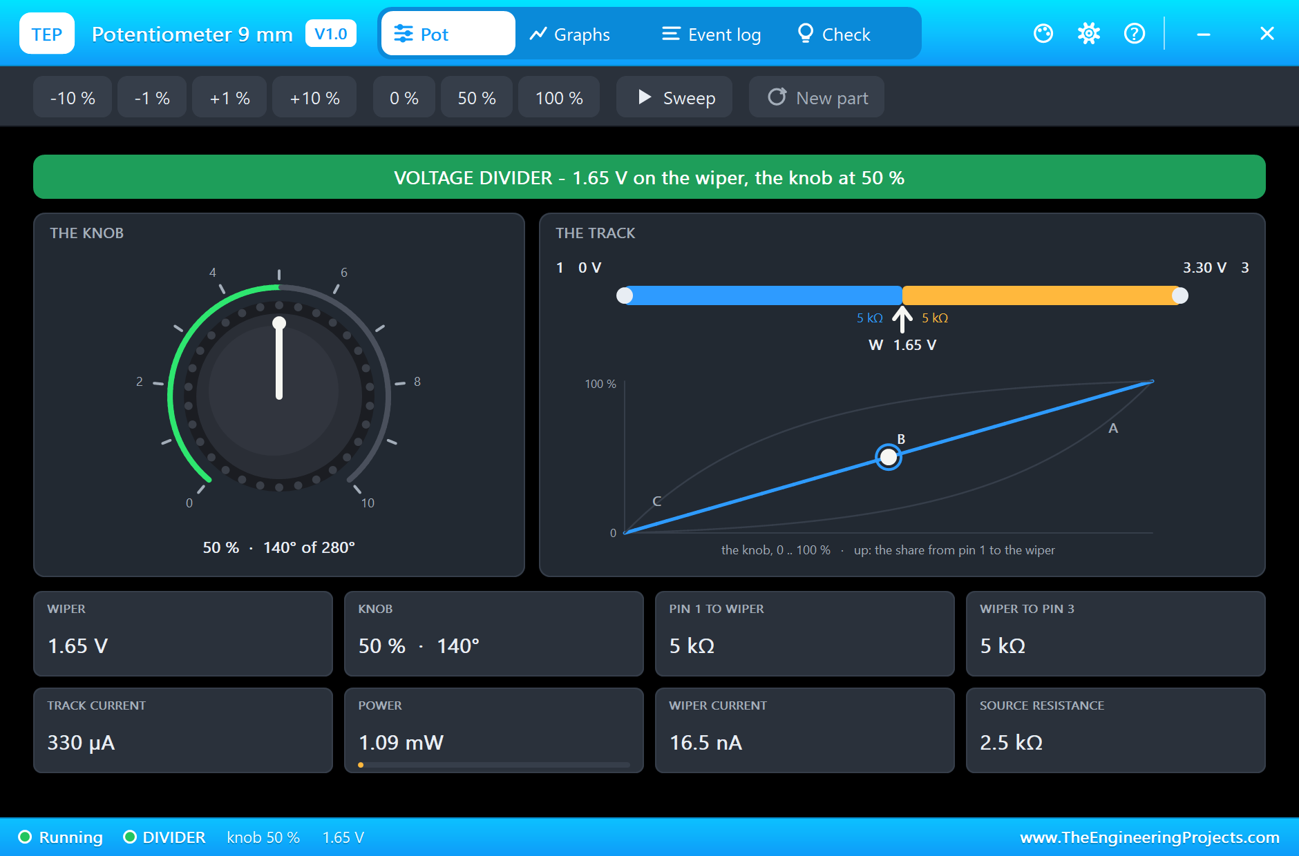
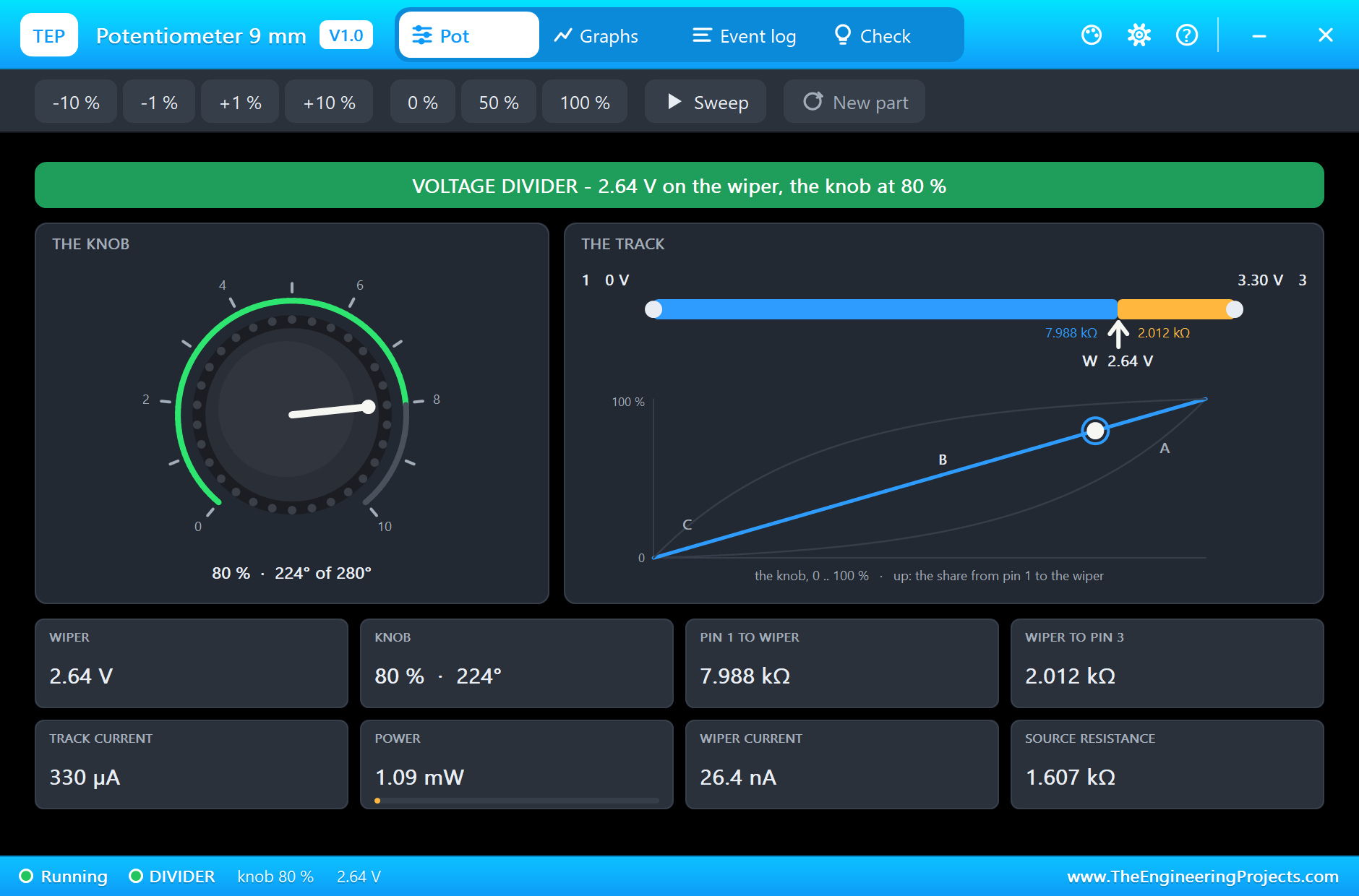
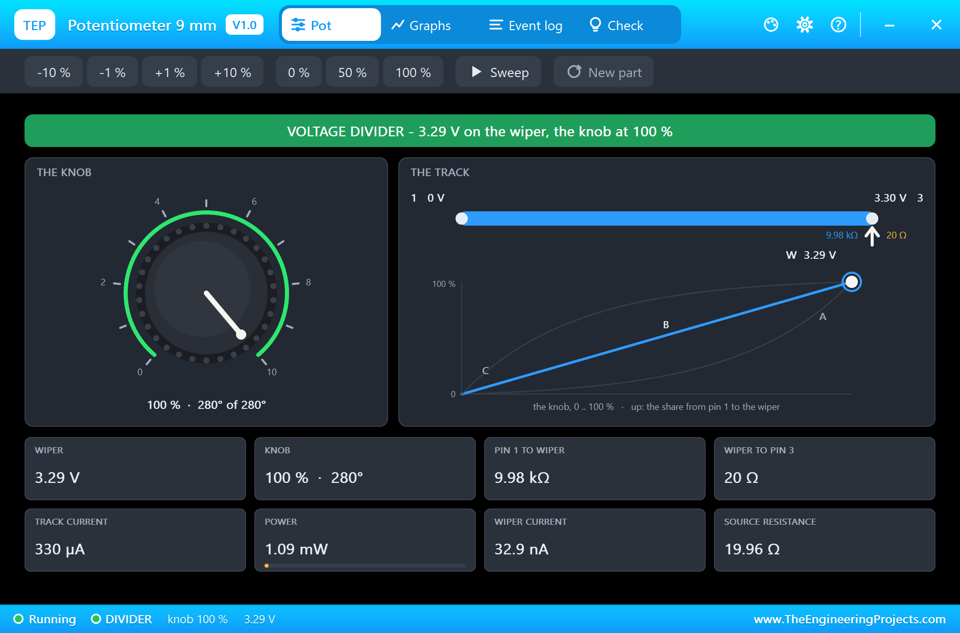
In the pot's window click the +10 % chip three times: the level rises and the lamp gets brighter. Here is the complete circuit while the simulation runs:
Off and On
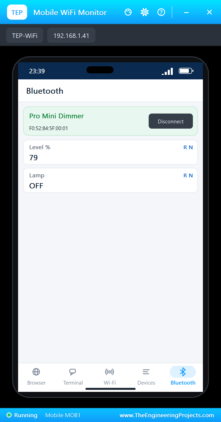
Click BOOTLOAD: the lamp goes off and the phone shows OFF - the level keeps its value. Click it again: back on at the same level. Then turn the knob all the way up: the filter climbs to 99 % in steps of 2 % and the lamp is at full light:
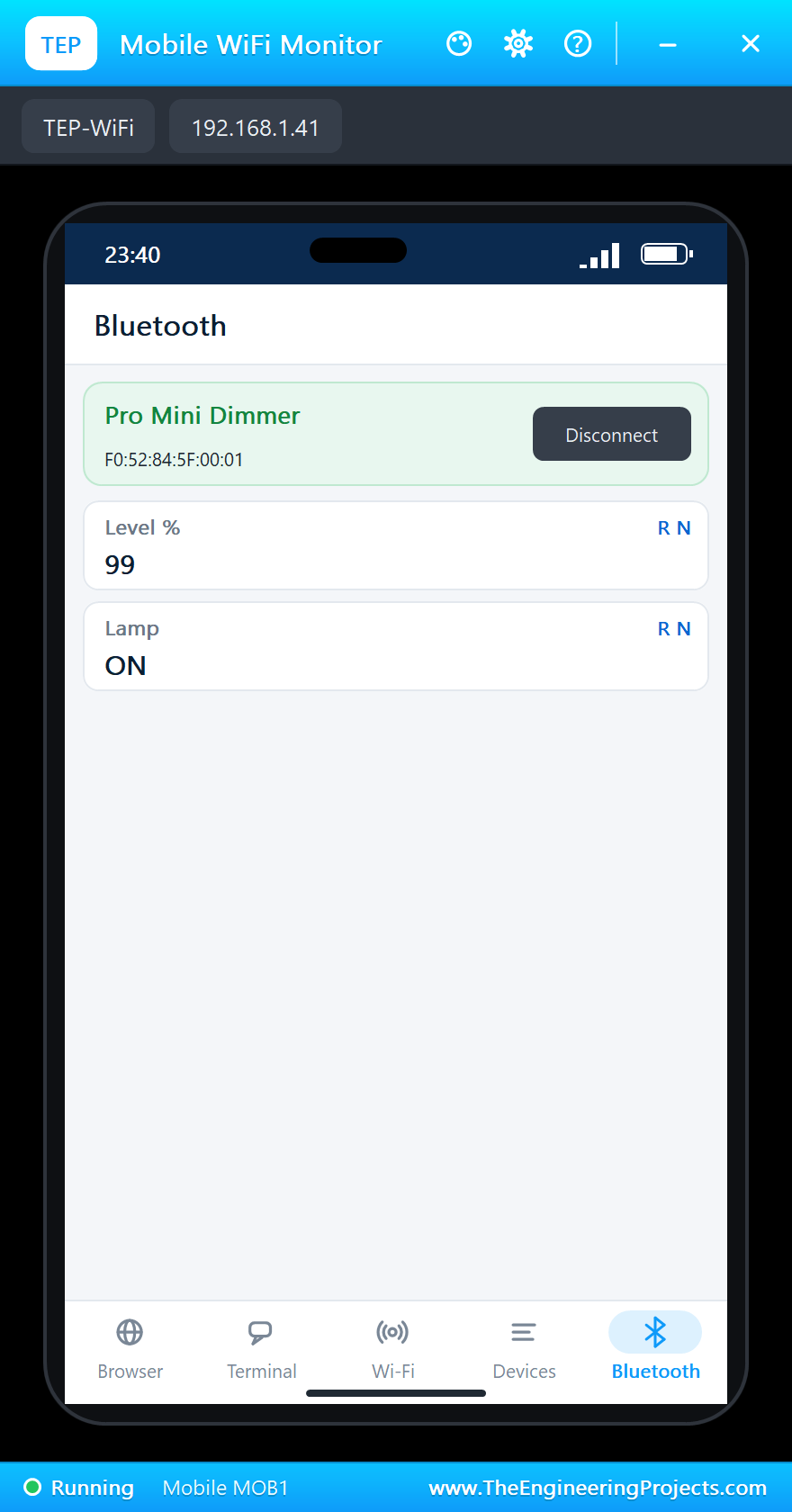
Phone connected
Lamp: ON, level 49 %
>> LEVEL 51 %
>> LEVEL 53 %
>> LEVEL 55 %
>> LEVEL 57 %
>> LEVEL 59 %
>> LEVEL 61 %
>> LEVEL 63 %
>> LEVEL 65 %
>> LEVEL 67 %
Lamp: ON, level 67 %
>> LEVEL 69 %
>> LEVEL 71 %
>> LEVEL 73 %
>> LEVEL 75 %
>> LEVEL 77 %
>> BUTTON: the lamp OFF
>> LEVEL 79 %
Lamp: OFF, level 79 %
>> BUTTON: the lamp ON
>> LEVEL 81 %
>> LEVEL 83 %
>> LEVEL 85 %
>> LEVEL 87 %
>> LEVEL 89 %
>> LEVEL 91 %
>> LEVEL 93 %
>> LEVEL 95 %
Lamp: ON, level 95 %
>> LEVEL 97 %
>> LEVEL 99 %
Lamp: ON, level 99 %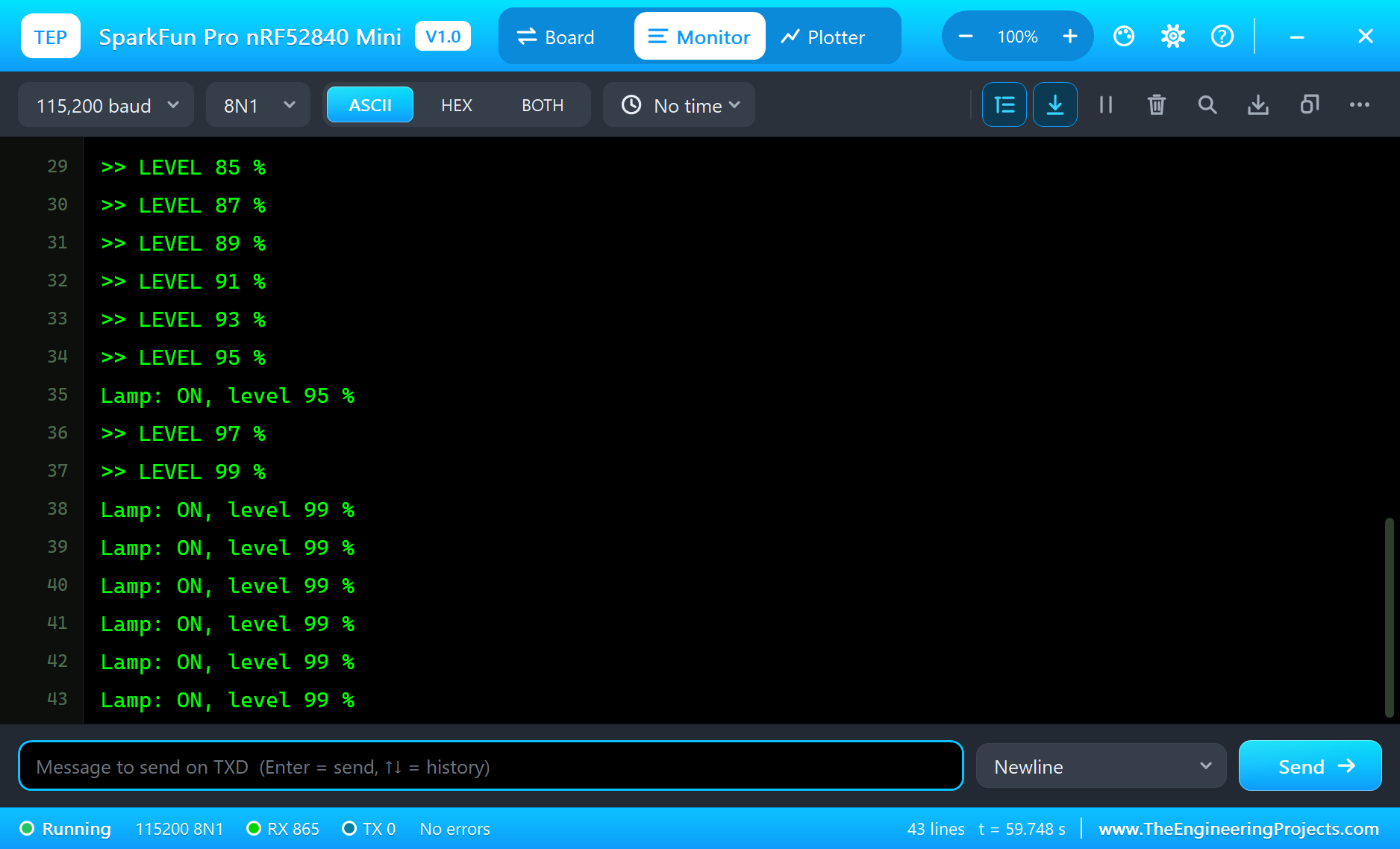
Why a Ground Pad beside Every Pin?
SparkFun gave this board a row of ground pads next to each header. A sensor cable can then take its signal and its ground from two neighbouring pads, which keeps the wiring short and the signal clean - handy for analog sensors and servos. In our part the pads are drawn; wire ground to the GND pin.
The Qwiic Socket
Qwiic is SparkFun's 4-wire I2C connector: ground, 3.3 V, SDA and SCL in a small polarised plug. Sensors, displays and buttons with Qwiic sockets daisy-chain without soldering. On this board the socket carries the Wire bus on P0.08 and P0.11; in our part SDA and SCL are pins next to it, so any I2C module from our libraries can be wired there.
Potentiometers and the ADC
A potentiometer between ground and 3.3 V divides the voltage; the wiper's voltage tells the position. The ADC turns 0 to 3.3 V into 0 to 1023. Never feed the pot from 5 V: above 3.3 V the reading saturates, and on the real nRF52840 the pin could be damaged. That is why the demo uses a +3.3V terminal.
PWM Dimming
An LED cannot be dimmed by lowering the voltage - it would just switch off. PWM switches it fully on and off hundreds of times a second; the share of on-time sets the average current and so the brightness. The eye sees a steady light.
Battery Power
The real board charges a single-cell LiPo through the JST socket from USB, and the ON/OFF switch cuts the regulator. A desk lamp on a battery would turn the radio down between changes and let the nRF52840 sleep.
Smoothing the Knob
The filter in readKnob() is an exponential moving average: each new reading moves the stored value by one sixteenth of the difference. Read ten times a second, that gives a time constant of about 1.6 s - the noise of a real potentiometer disappears, and a quick turn arrives as a smooth climb. That is why the monitor shows the level rising in steps of 2 % after each click: the filter walks towards the new position, and the 2 % rule decides which steps the phone hears about.
Why the Top Is 99 %
In the run the knob turned all the way up gave 99 %, not 100 %. The level is (avg / 16) * 100 / 1023 in integer maths, so only a reading of exactly 1023 gives 100 - a single count less ends at 99. Real potentiometers and ADCs rarely reach the last count, so a finished dimmer would map a small dead band at each end to 0 % and 100 %, for example with map() and constrain() on the range 10 .. 1013.
Gamma in Numbers
gamma8() squares the level: 50 % on the knob gives 50 x 50 x 255 / 10000 = 63, a duty cycle of about 25 %, and 10 % gives just 2 out of 255. Those low values are where the eye is most sensitive, so the bottom of the knob gets the fine steps it needs, while the top still reaches 255 - full power.
A White LED at 3.3 V
A white LED needs about 3 V before it lights. From a 3.3 V pin through 220 ohms that leaves only a few tenths of a volt for the resistor, so on real hardware the lamp would glow weakly. For a bright desk lamp, drive the LED (or a whole LED strip) through a logic-level MOSFET from the battery or a 5 V supply, and keep the pin only for the PWM signal. The sketch stays the same.
Linear or Logarithmic Pot?
Potentiometers come with a linear taper (often marked B) or a logarithmic one (marked A), which is made for volume knobs. With the gamma curve in the sketch, a linear 10k pot is the right choice: the software already bends the scale, and a logarithmic pot would bend it twice, crowding all the change into the last part of the turn. The 9 mm pot in the demo is linear, like the common B10K parts. Any value from 5k to 50k works with the ADC.
Bluetooth Notifications and the 2 % Rule
The phone subscribes to the level characteristic once; after that the board sends a value only when the sketch writes a new one. Reporting every 1 % step of a noisy knob would wake the radio many times a second. With the 2 % rule - plus 0 % and 100 % always - the phone still sees every real change, and the link stays quiet when nobody touches the knob.
Try It Yourself
- Fade the lamp smoothly to the new level instead of jumping.
- Add a writable characteristic so the phone can set the level.
- Turn the lamp off automatically after 30 minutes.
- Use a second pot on A3 for the colour of an RGB LED.
Ideas to Extend the Dimmer
- Add a light sensor and keep the room at a set brightness.
- Use a PIR sensor to switch the lamp on when somebody comes in.
- Store the last level in flash so it survives a reset.
- Show the level on a small OLED on the Qwiic socket.
Your Own Sketches
Write the sketch in the Arduino IDE with the board SparkFun Pro nRF52840 Mini (TEP Proteus), use Sketch > Export Compiled Binary and set the part's PROGRAM property to the .hex.
Moving to a Real Pro nRF52840 Mini
- Install SparkFun's nRF52 board package (based on Adafruit's) and select the Pro nRF52840 Mini.
- Port the Bluetooth part to Bluefruit, or keep ArduinoBLE-style code if your core supports it.
- Wire the pot to 3V3, GND and pin 4, and the LED with 220 ohm to pin 19.
- Use pin 13 with INPUT_PULLUP for the button and pin 7 for the blue LED.
- Press BOOTLOAD while tapping RESET to enter the bootloader if an upload fails.
The pins, the logic and the service stay the same; on the real board SparkFun's core takes the place of ours.
Properties of the Pro nRF52840 Mini
| Property | What it does |
|---|---|
| PROGRAM | the sketch: a .hex from TEP Boards for Proteus (the Pro nRF52840 Mini board) |
| MONITOR, BAUD, AUTOOPEN | the built-in serial monitor: on, its baud rate (115200), open at Run |
Troubleshooting
- The phone's list is empty: call
BLE.begin(), set a local name andBLE.advertise(); callBLE.poll()in the loop. - analogRead reads the wrong input: pass the pin number - A0 is pin 2, A2 is pin 4.
- The level jitters: smooth the readings and report only changes of 2 % or more.
- The lamp looks too bright at low levels: use a gamma curve.
- A number goes wrong above 32767: int is 16 bits in the simulation - use long.
Limitations of the Simulation
- The SPI library is not available on this board in the simulation: its SPI pins (2, 3, 30, 31) are the analog inputs here.
- The charger, the ON/OFF switch, the yellow charge LED, NFC and the QSPI flash are not modelled; one phone is the central.
- Your sketch gets 8 KB of RAM in the simulation, and int is 16 bits there.
- SparkFun and Qwiic are names of SparkFun Electronics, nRF52840 of Nordic Semiconductor ASA, MDBT50Q of Raytac and Arduino of Arduino; this library is not made or endorsed by them or by Labcenter.
- Tested in Proteus 8.5 in November 2026 (the demo as shipped, about 60 s of simulation). Proteus 7 is not supported.
So, that was all about the SparkFun Pro nRF52840 Mini Library for Proteus. I hope it helps you try your Bluetooth ideas in a simulation before the board is on your desk - the knob, the lamp and the phone, all on one sheet. If you have any questions, ask in the comments and I will help you out. Till the next tutorial, take care and have fun!

Comments
0