


Project Files of BH1750 Light Sensor Library for Proteus V1.1 (GY-302 + Arduino)
 Libraries
 Code
 Projects
 Simulation
bh1750-tep-v1-1-20ce9e1cf7b8435d95b28fdd71098a2d.zip
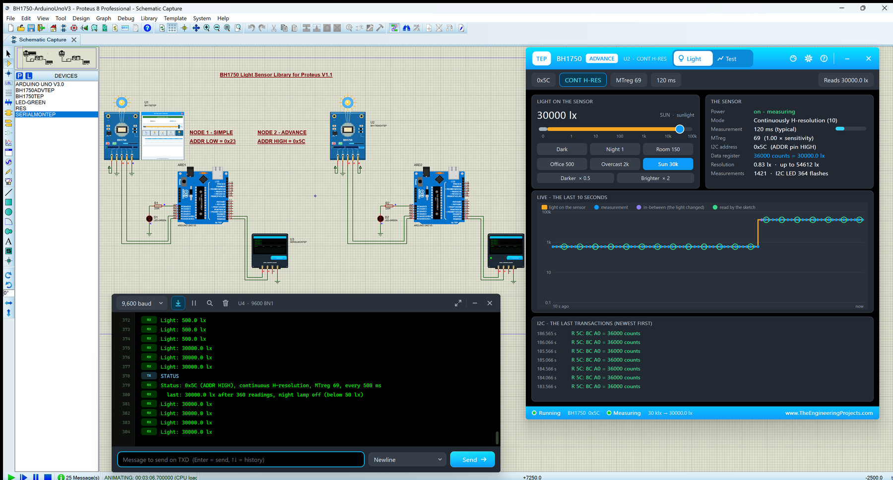
BH1750 Light Sensor Library for Proteus V1.1
BH1750 Light Sensor Library for Proteus V1.1 comes as a ZIP archive of 25 files (1.4 MB, 3.0 MB unpacked) holding Proteus library files, simulation model DLLs, a Proteus simulation, an Arduino sketch, an Arduino library, compiled HEX firmware and data files.
- LIBProteus library
- IDXProteus library index
- DLLProteus model
- DSNProteus simulation
- INOArduino sketch
- LIBArduino library
- HEXHEX firmware
- CSVData file
Description
This is the download page of BH1750 Light Sensor Library for Proteus V1.1, the file package of the tutorial BH1750 Light Sensor Library for Proteus V1.1 (GY-302 + Arduino), published on The Engineering Projects in September 2026. Here you get the ZIP file (1.4 MB) with the Proteus library files (LIB and IDX), the simulation model (DLL), a ready Proteus simulation, an Arduino sketch, an Arduino library, the compiled HEX firmware and data files, the list of files it contains, the README when there is one, and the installation steps in order.
What this library is
BH1750-Light-Sensor-Library-for-Proteus-v1.1.zip with BH1750 Simple and Advance (TEPBH1750.LIB and TEPBH1750.DLL), the TEP Serial Monitor and Arduino UNO libraries for Proteus, the two-UNO light sensor and night lamp simulation with its HEX file, the demo sketch with the claws BH1750 library and a README.
This is version 1.1; older or newer releases, when they exist, are listed in the Development tab.
What is inside the ZIP file
- ArduinoV3TEP.LIB – Proteus library, 95.6 KB
- TEPBH1750.LIB – Proteus library, 132.6 KB
- TEPSERIALMON.LIB – Proteus library, 11.1 KB
- ArduinoV3TEP.IDX – Library index, 830 B
- TEPBH1750.DLL – Simulation model, 363 KB
- TEPSERIALMON.DLL – Simulation model, 978 KB
- and 19 more, all listed in the File Structure tab
The archive unpacks to 3.0 MB and carries its own README (README.txt), shown in the README tab above.
How to download
Use the download panel at the top of this page: after the counter (30 seconds for guests, 10 for members) the black button unlocks and the ZIP file comes straight from our content network. If the browser opens it instead of saving, use Save as; extract the whole archive before using anything inside it.
How to install
- Step 1: Extract the ZIP file with Windows (Extract All), 7-Zip or WinRAR, keeping its folders.
- Step 2: Close Proteus and copy ArduinoV3TEP.LIB, TEPBH1750.LIB and TEPSERIALMON.LIB and ArduinoV3TEP.IDX into its LIBRARY folder (Proteus 8: C:\Program Files (x86)\Labcenter Electronics\Proteus 8 Professional\LIBRARY).
- Step 3: Copy TEPBH1750.DLL and TEPSERIALMON.DLL into the MODELS folder next to it, so the part simulates.
- Step 4: Start Proteus, press P and search for "ArduinoV3TEP"; place and wire it as in the tutorial.
- Step 5: In the Arduino IDE use Sketch → Include Library → Add .ZIP Library, then restart the IDE.
- Step 6: Open BH1750_Demo.ino, BH1750advanced.ino and BH1750autoadjust.ino and 3 more in the Arduino IDE, pick board and port and Verify (Export Compiled Binary gives the HEX).
- Step 7: In Proteus set the controller's Program File to BH1750_Demo.hex; on hardware, flash the same file.
- Step 8: Open BH1750-ArduinoUnoV3.pdsprj in Proteus and press Play.
Read the detailed guide
This page is for the files. The full tutorial, BH1750 Light Sensor Library for Proteus V1.1 (GY-302 + Arduino), explains the circuit and the code step by step and shows the working results and the simulation; read it before you build. Questions about the download or the installation go in the comments below; more Proteus downloads are listed further down this page.

File Structure
 File Structure
9 KB2.8 KB3 KB972 B1.3 KB1.9 KB8 KB2.3 KB31 B936 B464 B377 B1 KB8.2 KB830 B95.6 KB132.6 KB11.1 KB363 KB978 KB38.7 KB35.7 KB363 KB978 KB32.9 KBGallery12 images from the tutorialOpen the tutorial
 Gallery12 images from the tutorial
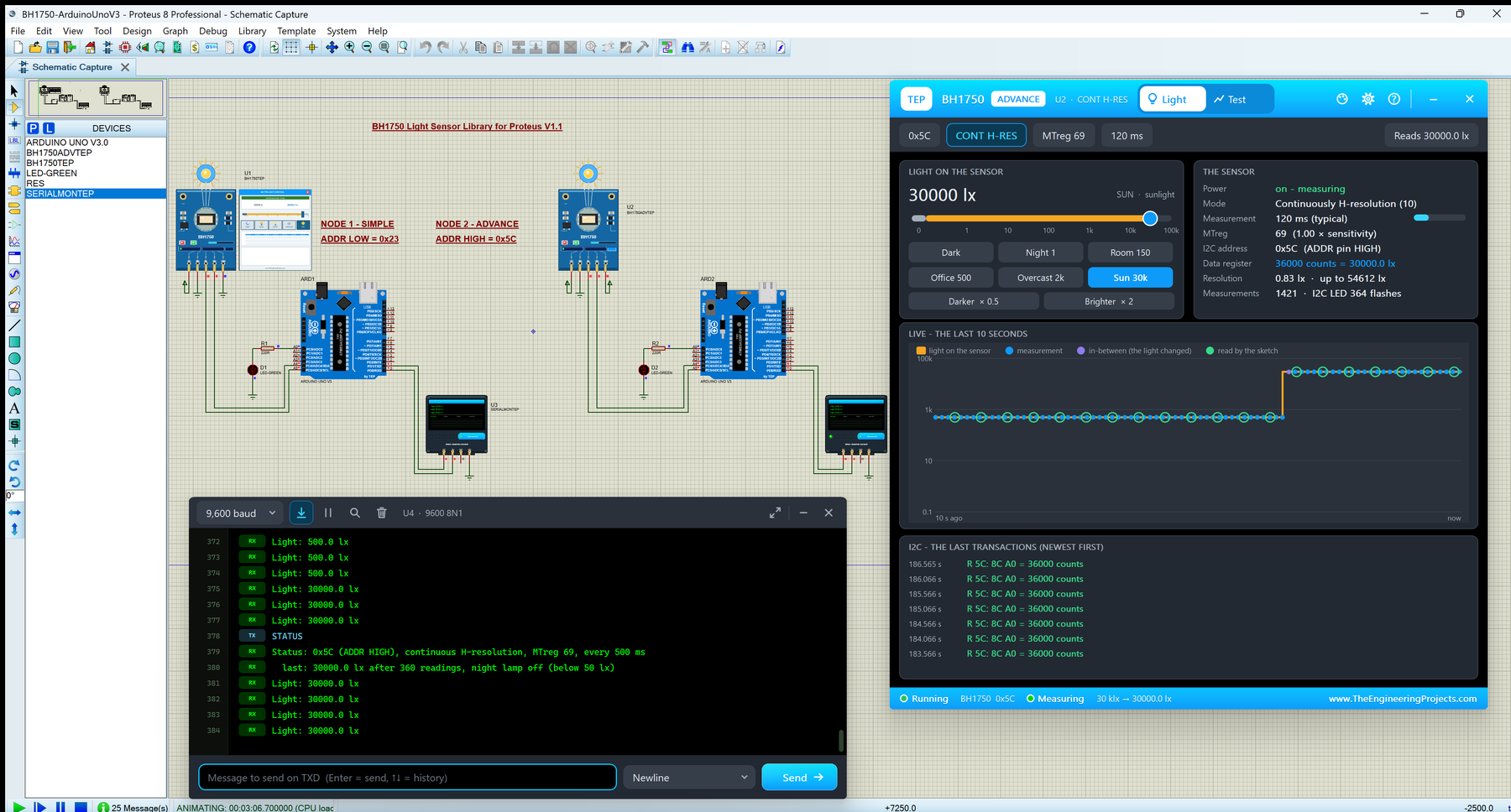
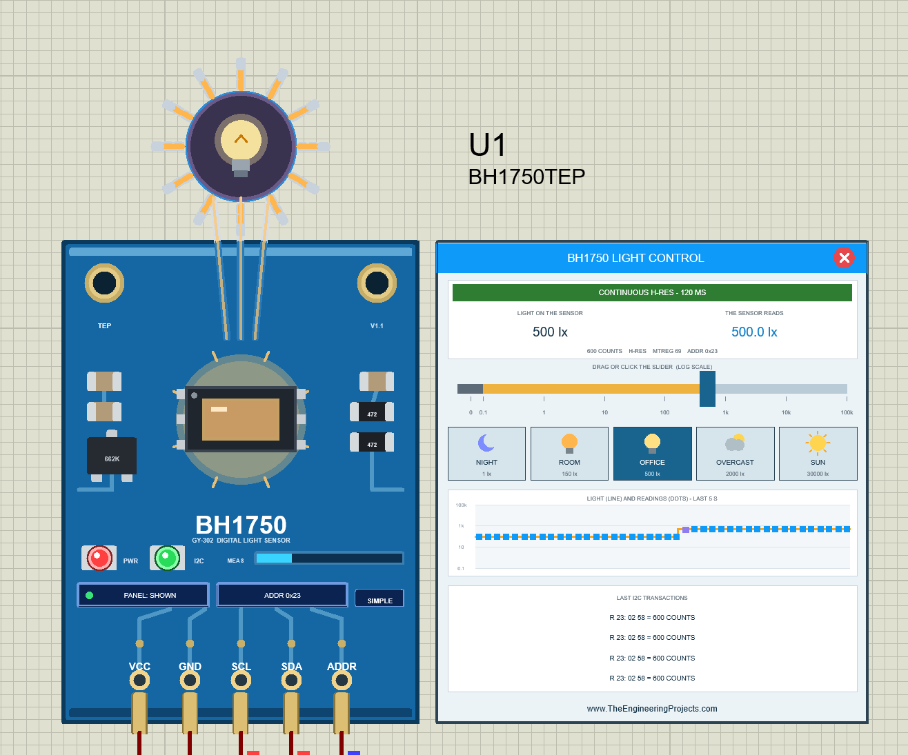
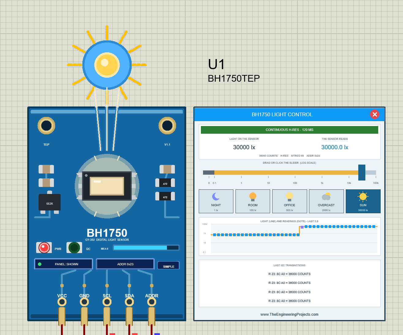
The circuit, the board and the results as they appear in BH1750 Light Sensor Library for Proteus V1.1 (GY-302 + Arduino). Open an image for its full size.
README
 README
BH1750 LIGHT SENSOR (GY-302) LIBRARY FOR PROTEUS - V1.1
Designed by The Engineering Projects
www.TheEngineeringProjects.com

IMPORTANT LINKS
Article (read it first - pictures, step by step, every feature explained):
  https://www.theengineeringprojects.com/2026/09/bh1750-light-sensor-library-for-proteus.html
Report a bug or suggest a feature (our forum):
  https://www.theengineeringprojects.com/forum/category/bh1750-proteus-library
The demo uses our TEP Serial Monitor Advance (included) instead of Proteus's
Virtual Terminal - its own article:
  https://www.theengineeringprojects.com/2026/10/serial-monitor-advance-proteus-library.html
Support us (the libraries are free):
  https://www.theengineeringprojects.com/donate

FILE STRUCTURE
BH1750-TEP-v1.1/
|-- Proteus Library Files/
|   |-- ArduinoV3TEP.IDX                              0.8 KB   its index -> LIBRARY folder
|   |-- ArduinoV3TEP.LIB                             95.6 KB   TEP Arduino UNO (demo) -> LIBRARY folder
|   |-- TEPBH1750.LIB                               132.6 KB   BH1750 Simple + Advance (2 devices) -> LIBRARY folder
|   |-- TEPSERIALMON.LIB                             11.1 KB   TEP Serial Monitor Advance -> LIBRARY folder
|-- Proteus Model Files/
|   |-- TEPBH1750.DLL                               363.0 KB   BH1750 model -> MODELS folder
|   |-- TEPSERIALMON.DLL                            978.0 KB   Serial Monitor model -> MODELS folder
|-- Proteus Simulation/
|   |-- BH1750_Demo.hex                              35.7 KB   both UNOs (demo sketch v1.1)
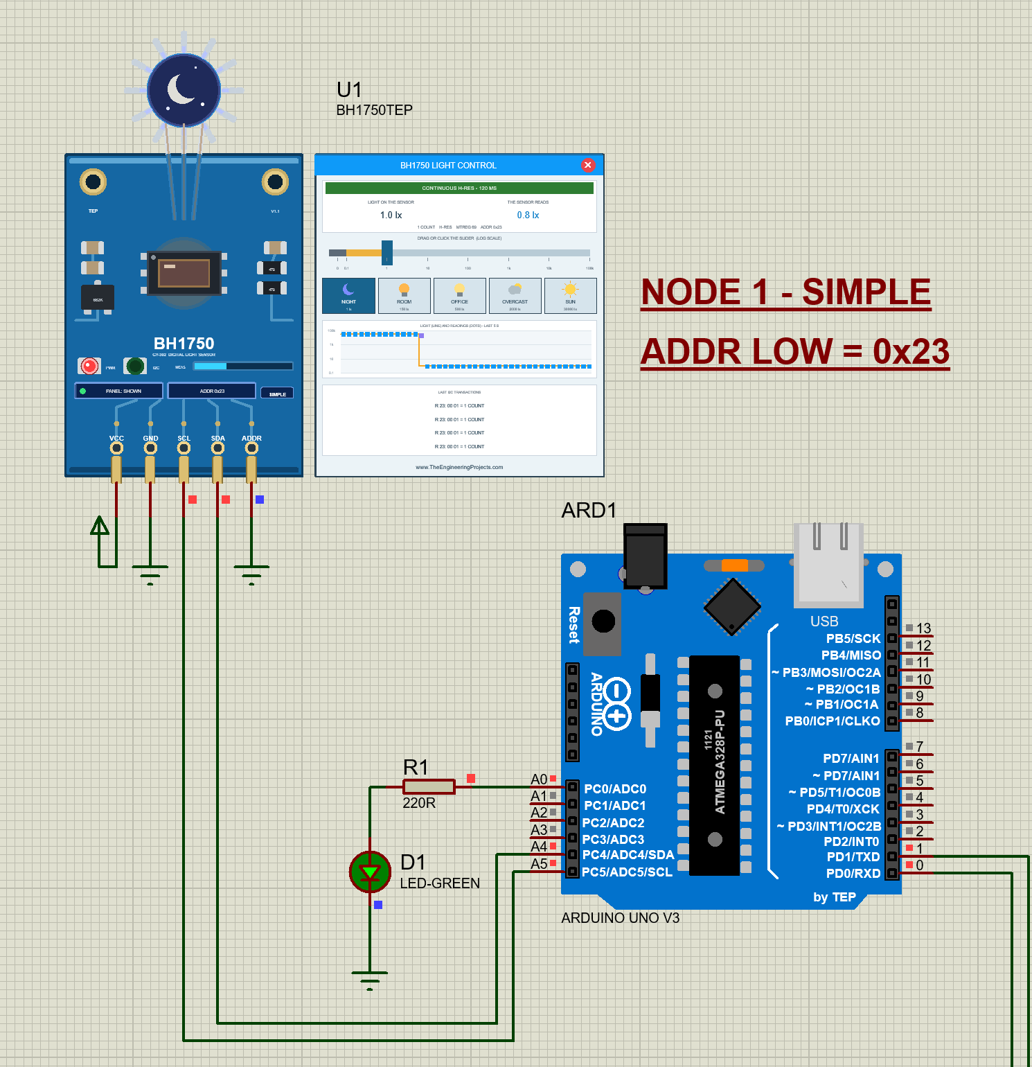
|   |-- BH1750-ArduinoUnoV3.pdsprj                   38.7 KB   demo: UNO 1 + BH1750 Simple (0x23), UNO 2 + Advance (0x5C)
|   |-- TEPBH1750.DLL                               363.0 KB   copy of the model so the demo runs as is
|   |-- TEPSERIALMON.DLL                            978.0 KB   copy of the monitor model
|-- Arduino Code/
|   |-- BH1750_Demo/BH1750_Demo.ino                   9.0 KB   the demo sketch (source of the .hex)
|   |-- libraries/BH1750/                            31.3 KB   BH1750 1.3.0 by Christopher Laws (MIT, LICENSE), 13 files
|-- README.txt                                      ~34.4 KB   this file
Total: 3.00 MB (unzipped). The C++ source code of the model is not included.

WHAT IS IT?
A simulation model of the ROHM BH1750FVI digital light sensor on the common blue
GY-302 module for Proteus 8. Your Arduino talks to it exactly as to the real one
over I2C - at address 0x23 (ADDR LOW or open) or 0x5C (ADDR HIGH) - and the
popular claws "BH1750" Arduino library runs unmodified: begin, configure (the six
measurement modes), setMTreg, measurementReady, readLightLevel. The model has the
chip's opcodes (Power Down, Power On, Reset, Continuously / One Time H-resolution,
H-resolution2 and L-resolution, the MTreg commands), its measurement times (120 ms
in H-resolution, 16 ms in L-resolution, x MTreg / 69; the datasheet's maximum 180
/ 24 ms with TIMING = MAX), the counts it makes (1.2 counts per lux at MTreg 69,
twice that in H-resolution2, 4-count steps in L-resolution, 65535 at most), the
Power Down after a One Time measurement, and v1.1 integrates the light over every
measurement as the real photodiode does. You set the light on the sensor with a
slider (0 lx to 100 klx, log scale) or five light scenes - night, room, office,
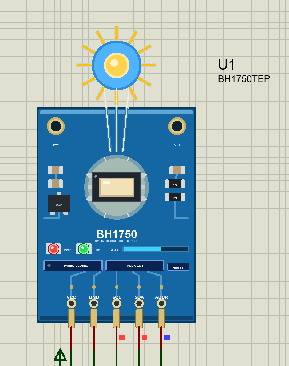
overcast, sun. The part looks like the blue GY-302: the BH1750 with its optical
window in the middle, the 662K regulator and the I2C pull-ups, the gold mounting
holes, the 5-pin header. While the simulation runs the sensor window glows with
the light and a halo grows around it, a round "sky" above the board shows a moon,
a lamp, a cloud or the sun with rays that grow with the light and three beams
down to the window, the MEAS bar fills during every measurement and the ADDR box
shows 0x23 / 0x5C. The red PWR LED shows the supply and the green I2C LED flashes
on every transaction to this sensor (both TEP additions - the GY-302 has no LED).

TWO DEVICES IN ONE LIBRARY (search "BH1750" in Pick Devices):
  BH1750 Simple   device BH1750TEP     "BH1750 Light Sensor Module (GY-302) - Simple"
                  On-Sheet Panel: a light panel on the schematic next to the
                  sensor - the sensor's state (NO POWER / POWER DOWN / CONTINUOUS
                  H-RES - 120 MS ...), the light on the sensor and what the sensor
                  reads (counts, mode, MTreg, address), a log slider (drag or
                  click), the five light scenes, a live chart of the last 5 s
                  (the light as a line, every measurement as a dot - an
                  in-between measurement in violet) and the last I2C transactions
                  decoded (W 23: 10 CONT H-RES, R 23: 02 58 = 600 COUNTS ...). The
                  red X in the panel's header closes it, the PANEL button on the
                  board opens it again. Your v1.0 designs keep working with this
                  device.
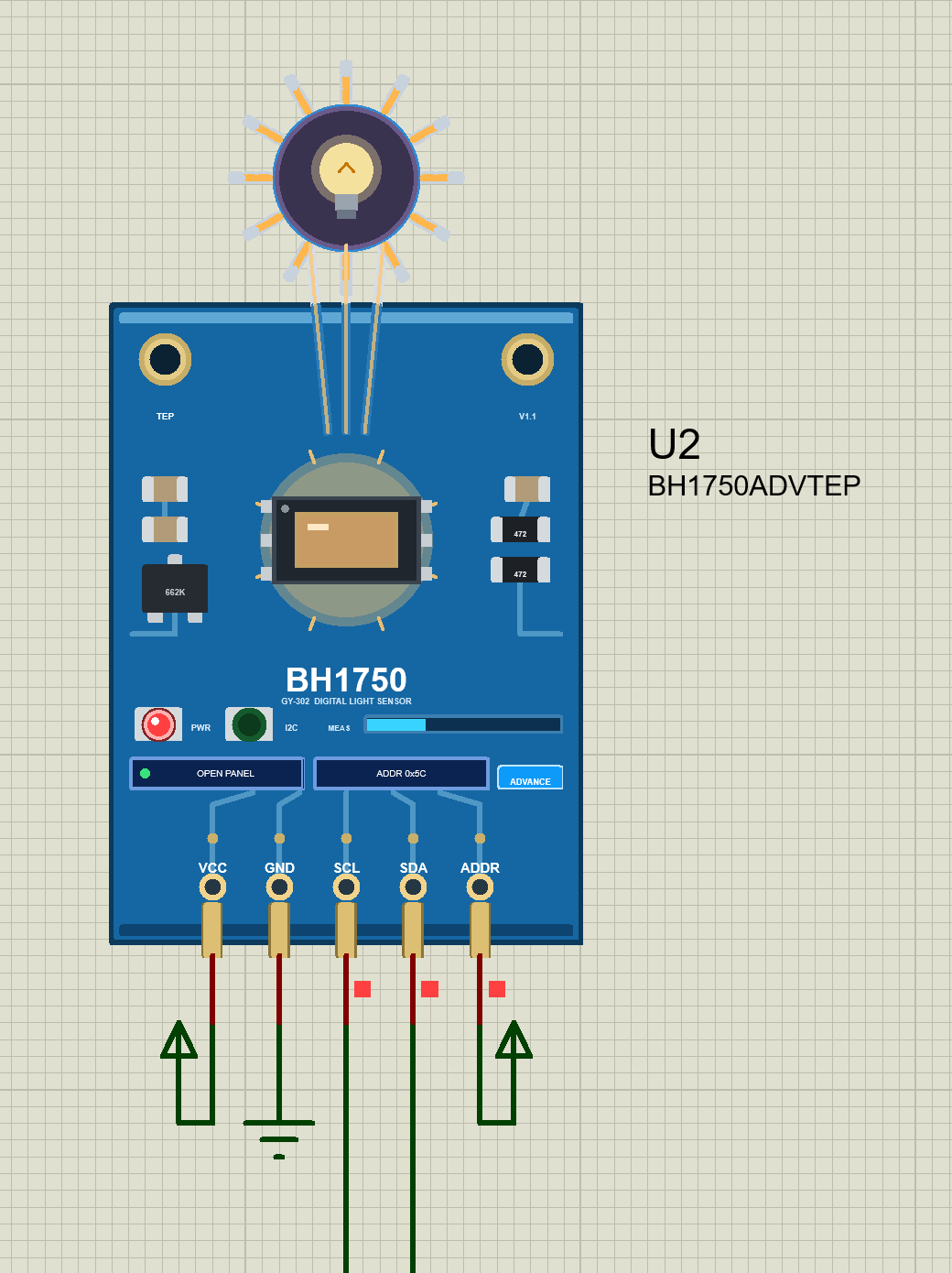
  BH1750 Advance  device BH1750ADVTEP  "BH1750 Light Sensor Module (GY-302) - Advance"
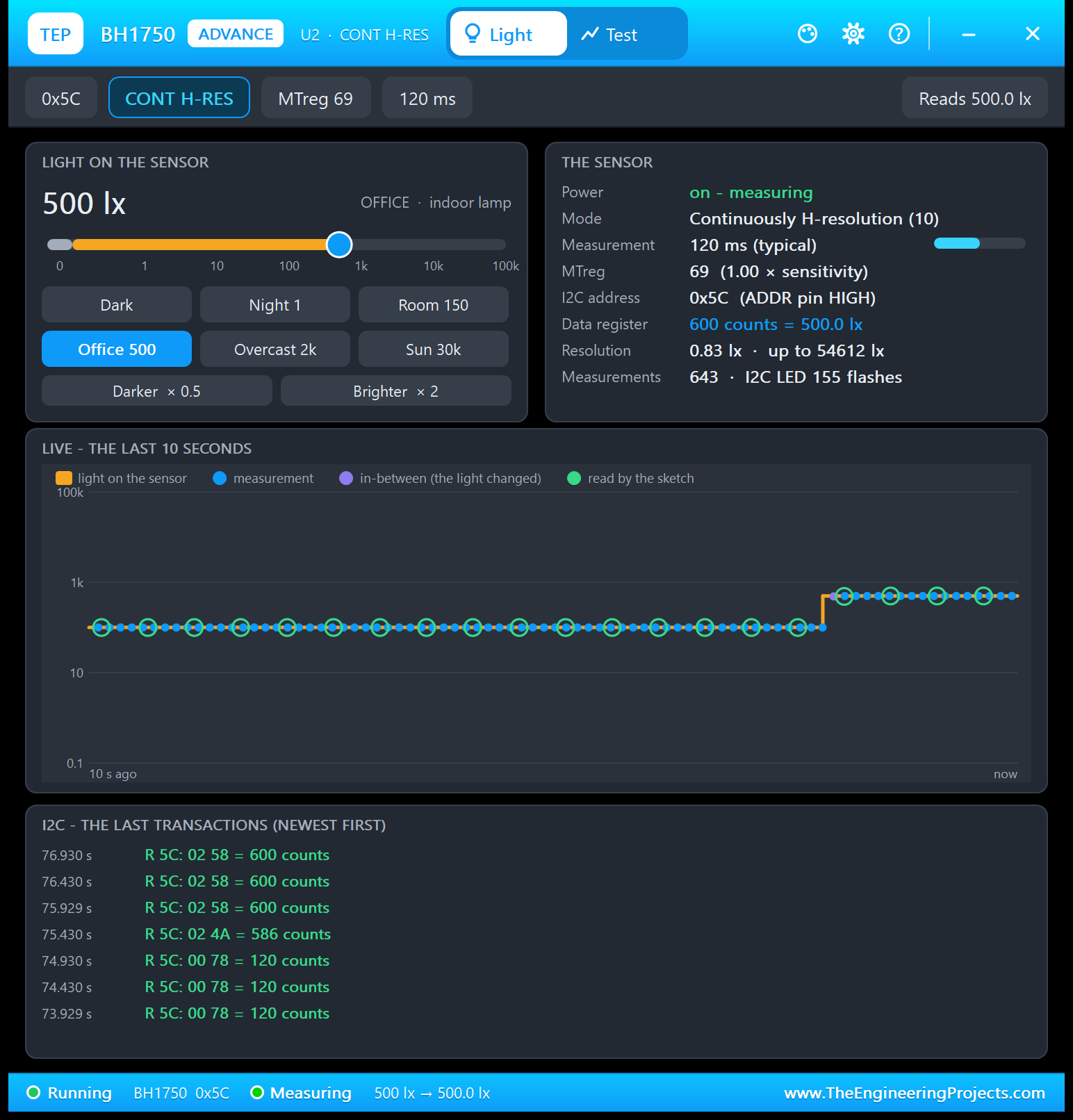
                  Pop-Up Panel: only the sensor board on the schematic; at Run a
                  TEP pop-up window opens - the same look as the TEP Serial
                  Monitor (move it by its header, resize it, minimise it). The
                  tabs Light and Test sit in the header; the gear and ? icons open
                  Settings and Help; the palette icon switches the theme:
                    Light     the light on the sensor (value, log slider, Dark /
                              Night / Room / Office / Overcast / Sun, Darker x 0.5
                              / Brighter x 2), THE SENSOR (power, mode, the
                              measurement time with a progress bar, MTreg, the I2C
                              address and the ADDR pin, the data register in
                              counts and lux, resolution and range, measurements
                              and I2C LED flashes), a live chart of the last 10 s
                              (light, measurements, in-between measurements, the
                              sketch's reads) and the last I2C transactions
                    Test      four tools measured on the model with your sketch:
                              I2C check, Timing, Step response, Lux sweep (see THE
                              TEST TOOLS below)
                    Settings  theme (TEP Dark / Light), text size, open at Run,
                              window size - remembered for your Windows user
                    Help      Help & Support like the TEP Serial Monitor: report a
                              bug, suggest a feature, article, user guide, updates,
                              donate, website, forum; Copy diagnostics (sensor,
                              board, light, data register, I2C, the sketch's set-up,
                              test results) for a bug report
                  The OPEN PANEL button on the board opens the window again
                  after you close it.
Both devices use the same model (TEPBH1750.DLL) and the same properties.

NEW IN V1.1
* Two devices: BH1750 Simple (light panel on the sheet, close / open) and BH1750
  Advance (pop-up window with the light controls, four test tools, settings and
  help) - see above.
* Board: the blue GY-302 drawn clean and bold - the BH1750 with its optical
  window, the 662K regulator, the 472 pull-ups, the capacitors, two gold
  mounting holes - with a glowing window and a halo, the sky above the board
  (moon / lamp / cloud / sun, 12 rays with 0 - 3 lit segments, three beams), the
  MEAS bar, the ADDR box (0x23 / 0x5C, live), a PANEL / OPEN PANEL button and a
  SIMPLE / ADVANCE badge. LEDs: PWR (red) and I2C (green) - both TEP additions
  (the real GY-302 has no LED): PWR lights with the supply, I2C for 0.3 s
  (simulation time) after every transaction to this sensor.
* Model - real measurement timing: H-resolution and H-resolution2 120 ms, L-
  resolution 16 ms, both x MTreg / 69 (MTreg 31 = 54 ms ... 254 = 442 ms in H-
  resolution); TIMING = MAX uses the datasheet's maximum 180 / 24 ms. The result
  is ready at the end of the measurement (the data register keeps the last one
  until then); continuous modes start the next measurement at once; One Time
  modes go to Power Down after their measurement.
* Model - the light is INTEGRATED over every measurement window like the real
  photodiode: a light change in the middle of a measurement gives one in-between
  reading (v1.0 used the light at the moment the result was read).
* Model - MTreg sensitivity: MTreg changes the counts per lux (x MTreg / 69) and
  the measurement time; a new MTreg applies to the next measurement (the library
  re-sends the mode after setMTreg, which starts one). Reset (07) is ignored in
  Power Down, as in the datasheet. ACCURACY (0.96 - 1.44, typical 1.2) plays a
  sensor that reads high or low.
* Model - the ADDR pin: LOW or open = 0x23 (the module's pull-down), HIGH = 0x5C;
  the ADDR box on the board and the pop-up show the address; a transaction to
  the other BH1750 address gets no ACK (logged once).
* Model - an I2C transaction log: every transaction with its time, the address,
  R / W, ACK / NACK, the opcodes decoded, the value read and the measurement it
  came from, and the measured SCL clock - the panels, the I2C check and Copy
  diagnostics show it.
* The demo: ONE project with two UNOs - UNO 1 with BH1750 Simple at 0x23 (ADDR to
  GND), UNO 2 with BH1750 Advance at 0x5C (ADDR to VCC) - each with the TEP
  Serial Monitor Advance instead of the Virtual Terminal (U3 = UNO 1, U4 = UNO 2,
  quick buttons) and a night-lamp LED on A0.
* The demo sketch (v1.1) keeps every v1.0 line ("Light: 123.4 lx" every 500 ms)
  and adds: the address found (0x23 or 0x5C), the night lamp on A0 (lines only
  when it switches - no periodic status lines), and the commands HELP, STATUS,
  MODE H / H2 / L, ONCE, CONT, MTREG n, EVERY ms, NIGHT lx, READ.
* Version 1.1 everywhere; the C++ source code is no longer included (and neither
  is the Arduino AVR core archive - its GitHub link is below).

TEST STATUS
v1.1: verified in Proteus 8.5 on 8 Oct 2026 with this package's demo: both
Serial Monitors (9600) and U2's pop-up open at Run (no system caption row); U3
"BH1750 found at 0x23 (ADDR
LOW) ...", U4 "... 0x5C (ADDR HIGH) ...", then "Light: 100.0 lx". U1 (Simple):
NIGHT "Light: 0.8 lx" + "Night lamp ON (0.8 lx < 50 lx)", LED D1 lit, the moon;
SUN "Light: 30000.0 lx" + "Night lamp OFF (30000.0 lx)", the sun; the red X and
PANEL. U3: MODE L "Mode: continuous L-resolution (4 lx steps, 16 ms)"; MODE H2 at
SUN "Light: 27306.2 lx" (full scale - after one 15000.0 lx line, see THE DEMO
SKETCH); EVERY 0 "Readings paused - type EVERY 500 to go on"; READ. U4: ONCE,
MTREG 254 "MTreg 254: 3.68 x sensitivity, 441 ms per measurement", then 100.1
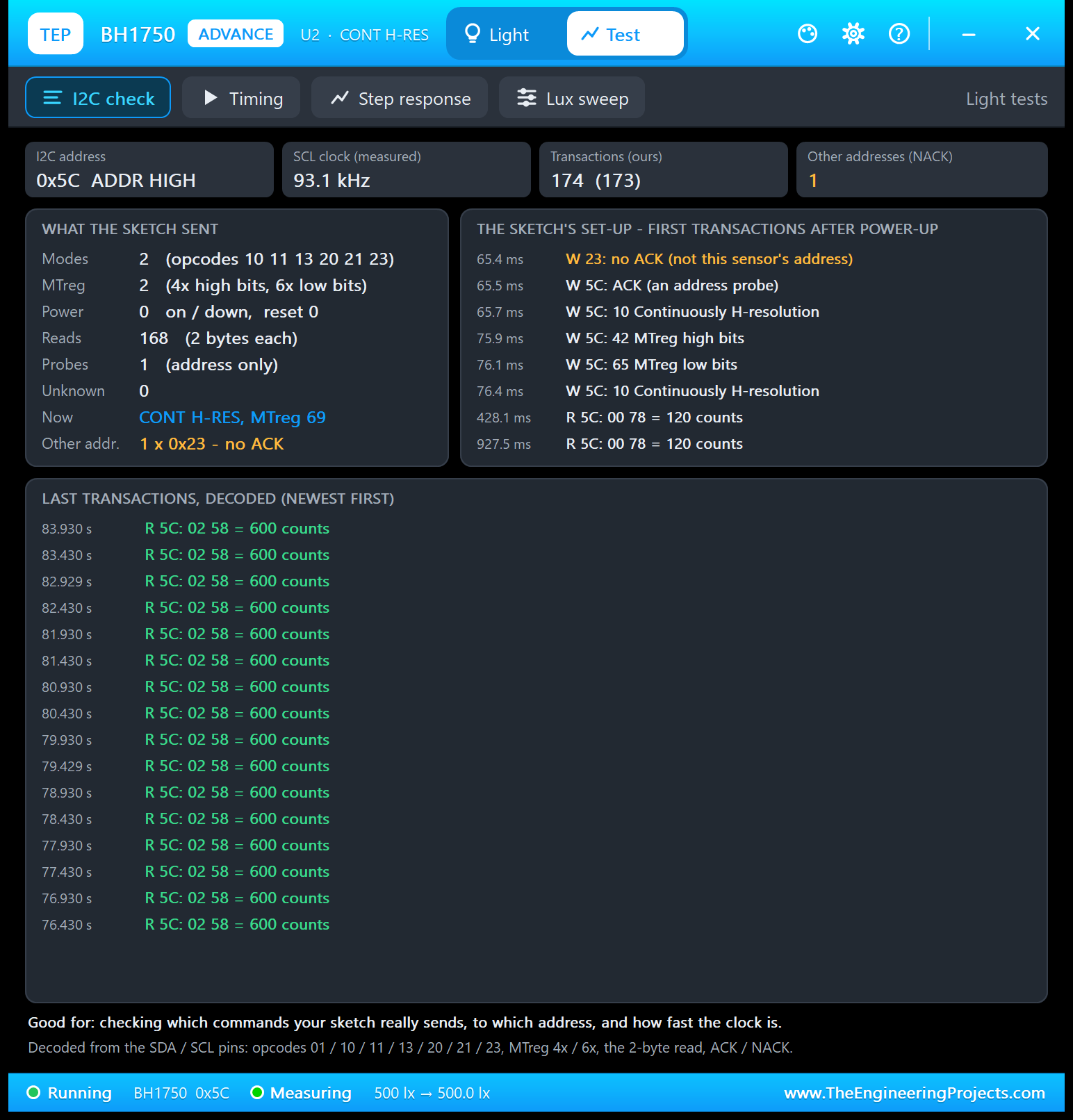
lx. U2 (Advance) tools: I2C check (SCL 93.1 kHz measured; W 23 no ACK, W 5C probe
ACK, 10 / 42 / 65 / 10), Timing 5 s (41 measurements of 120.0 ms, 10 reads every
500 ms, 10 fresh / 0 again / 0 early, the value 51 ms old on average (9 - 109);
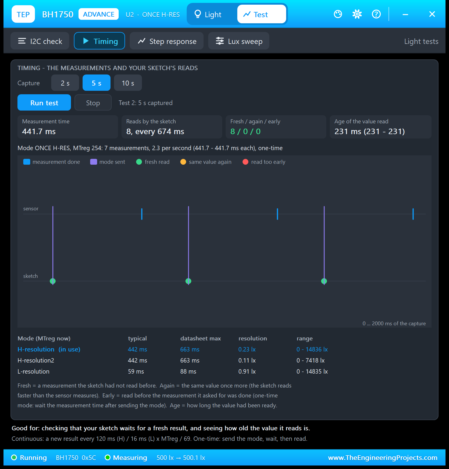
with ONCE + MTreg 254: 441.7 ms, 7 reads every 674 ms, 7 / 0 / 0, 231 ms old),
Step response 100 -> 1000 lx x 5 (an in-between value in 5 of 5 runs, 50 ms after
the step on average; the first full result after 170 ms; the sketch had the new
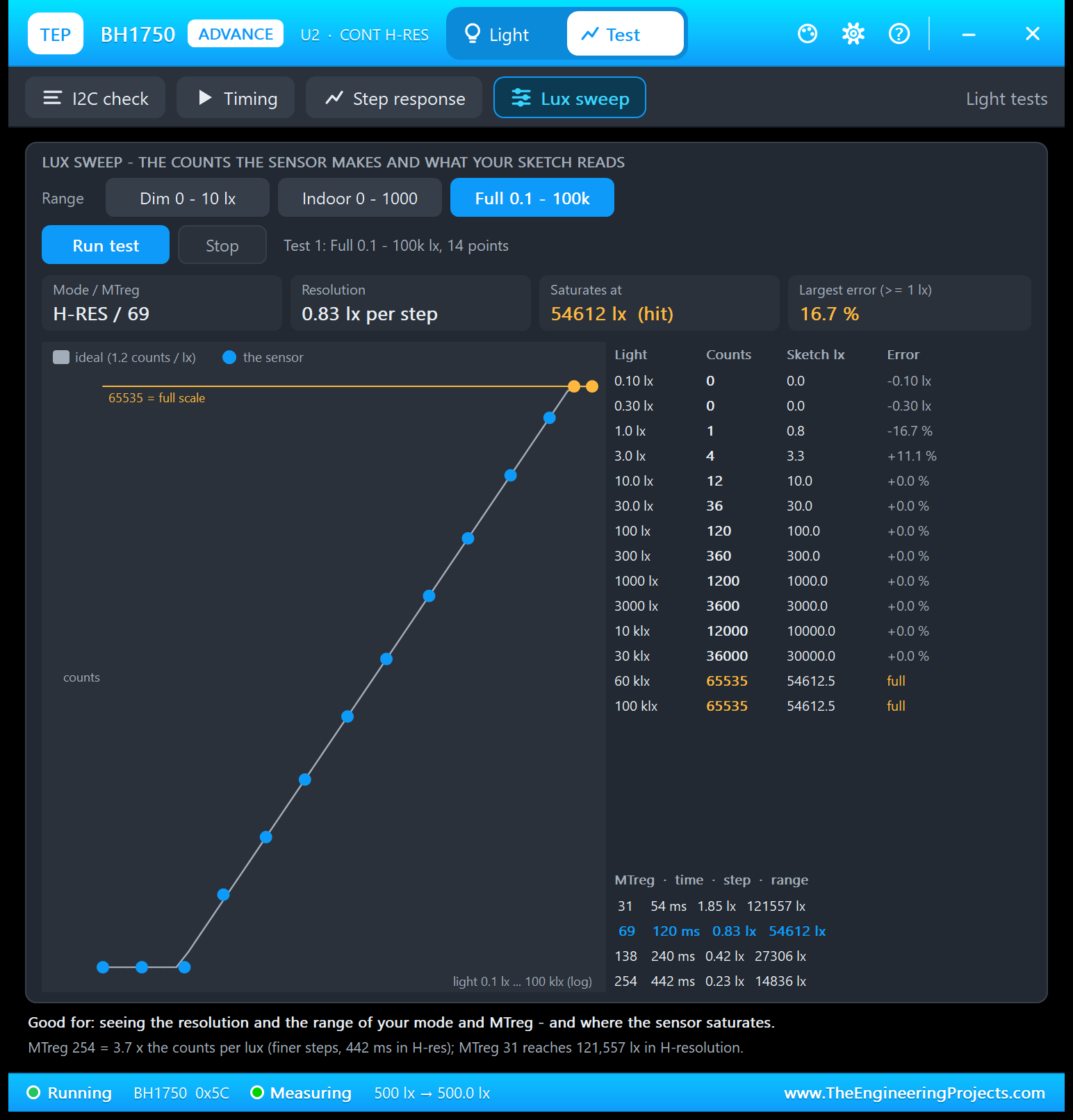
light after 436 ms), Lux sweep Full (0.5 lx -> 1 count = 0.8 lx; 60 and 100 klx
-> 65535 = 54612.5 lx; largest error 16.7 %), Settings, Help (all 8 cards with
the live links), close and OPEN PANEL.
A v1.0 design keeps running - verified in Proteus 8.5 on 8 Oct 2026: the v1.0
release demo (v1.0 symbol, v1.0 sketch, Virtual Terminal) with the v1.1
TEPBH1750.DLL showed the v1.0 panel ("LIGHT LEVEL 100.0 lx", 0 - 2000 lx, "DRAG
TO CHANGE"), printed "TEP BH1750 light sensor demo" and "Light: 100.0 lx"; a click
on the slider set 1180.0 lx and the terminal printed "Light: 1180.0 lx".
  1475 automatic checks on a PC, 0 failed:
  27 = the v1.0 regression test (tests.cpp, unchanged: I2C ACK / NACK, both
  addresses, byte order, timing, continuous / one-time, reset, power-down, MTreg,
  saturation, L-resolution, the v1.0 slider) compiled against the v1.1 model;
  58 on the chip with the unmodified claws BH1750 library 1.3.0 bit by bit on the
  I2C pins (opcodes, times, counts, the integrated light, one-time, MTreg, ADDR,
  power, the transaction log; begin() = 10, 42 65, 10; a read right after begin()
  gives 0 lx like the real chip; the library's own error messages); 20 on the
  test tools alone; 50 with the real v1.1 demo sketch on TWO UNOs against the
  complete Proteus model (every v1.0 output line, the address search, the night
  lamp, every command, the scenes and the slider, H-resolution2 saturating at
  27306.2 lx, an in-between reading, the three measuring tools, the v1.0
  STEP_TIME test, every line at most 80 characters); 91 on the complete
  Proteus model (a design with the v1.0 symbol: the v1.0 panel and slider
  exactly; both devices, the red X / PANEL,
  the pop-up without a caption row, its pages, all 8 Help links, the board's
  LEDs / MEAS bar / ADDR box / sky / rays / beams / window, TIMING / ACCURACY /
  LUX_MAX, power); 1229 on the rendered boards and pop-up windows (every page
  fits in TEP Dark and Light, at Large text and 150 % DPI; every tool's hint
  lines fit the window; every header state fits).
v1.0 (28 Sep 2026): the v1.0 demo was run in Proteus 8.5 SP0 - "Light: 100.0
  lx", the slider at both ends (0.0 / 2000.0 lx) and in between (991.1 lx in,
  990.8 lx read), STEP_TIME 3 (100.0 then 1000.0 lx), ADDR to ground.

INSTALLATION (about 2 minutes)
1. Close Proteus. Extract the WHOLE ZIP to a normal folder (e.g. Desktop).
2. Copy everything in "Proteus Library Files" (TEPBH1750.LIB with both devices,
   TEPSERIALMON.LIB and the TEP Arduino UNO V3 library ArduinoV3TEP.LIB / .IDX
   used by the demo) to the LIBRARY folder of Proteus, for example:
     C:\Program Files (x86)\Labcenter Electronics\Proteus 8 Professional\LIBRARY
   (on some PCs: C:\ProgramData\Labcenter Electronics\Proteus 8 Professional\
   LIBRARY - use the folder that already holds Proteus's own .LIB files).
3. Copy TEPBH1750.DLL and TEPSERIALMON.DLL from "Proteus Model Files" to the
   MODELS folder (...\Proteus 8 Professional\MODELS).
4. Updating from v1.0: replace TEPBH1750.LIB and TEPBH1750.DLL, and delete
   TEPBH1750.IDX if there is one in the LIBRARY folder. A v1.0 design keeps its
   v1.0 symbol: it runs with the new model and shows the v1.0 slider panel
   exactly as before (without the v1.1 board parts) - re-pick the part to get
   the v1.1 symbol.
5. Start Proteus. In Pick Devices (P) search "BH1750": you get the Simple and the
   Advance device (category Sensors > Light, as in v1.0).

RUN THE DEMO
"Proteus Simulation\BH1750-ArduinoUnoV3.pdsprj" - keep the .hex file and the two
DLLs beside the project.
  UNO 1 (ARD1): BH1750 Simple (U1, ADDR to GND = 0x23), Serial Monitor U3.
  UNO 2 (ARD2): BH1750 Advance (U2, ADDR to VCC = 0x5C), Serial Monitor U4.
  Both run BH1750_Demo.hex. An LED (D1 / D2) with 220 ohm on A0 of each UNO: the
  night lamp.
  1. Press Run. Both monitor windows open (9600 baud) and so does U2's pop-up.
     U3 shows "TEP BH1750 light sensor demo v1.1", "BH1750 found at 0x23 (ADDR
     LOW): continuous H-resolution, MTreg 69" and the command list, then "Light:
     100.0 lx" every 500 ms; U4 the same with "found at 0x5C (ADDR HIGH)". The
     PWR LEDs are lit, the I2C LEDs flash with every reading, the MEAS bars fill
     every 120 ms, the sky shows a lamp.
  2. U1: click the scenes on the panel - NIGHT (1 lx): "Light: 0.8 lx" (one count
     is 0.83 lx) and "Night lamp ON (0.8 lx < 50 lx)", LED D1 lights, the sky
     turns to night with a moon; SUN (30000 lx): "Light: 30000.0 lx", "Night lamp
     OFF (30000.0 lx)", the sun with all rays lit and a bright window. Drag the
     slider. Right after a change one reading can be in between (the BH1750
     averages the light over its 120 ms measurement - the chart shows that
     measurement in violet). Close the panel with its red X and open it with
     PANEL on the board.
  3. U3 / U4 quick buttons: U3 STATUS, MODE L (16 ms, 4 lx steps), MODE H, NIGHT
     200 (the lamp lights below 200 lx: try ROOM and OFFICE); U4 STATUS, ONCE (a
     One Time measurement before every reading - the chip powers down between),
     CONT, MTREG 254 ("MTreg 254: 3.68 x sensitivity, 441 ms per measurement" -
     the library still prints the same lux). Type HELP, MODE H2 (0.5 lx steps;
     at SUN it saturates: "Light: 27306.2 lx"), EVERY 1000, EVERY 0 (pause),
     READ.
  4. U2 (Advance): Light page - the slider, the scenes, Darker / Brighter; watch
     THE SENSOR card and the live chart. Test page:
       I2C check: the address, the measured SCL clock (93.1 kHz in our Proteus
         run with Wire at 100 kHz), what the sketch sent (the address search:
         "W 23: no ACK" - U2 is at 0x5C - then "W 5C: ACK (an address probe)",
         begin(): 10, 42 65 (MTreg 69), 10, then a 2-byte read every 500 ms).
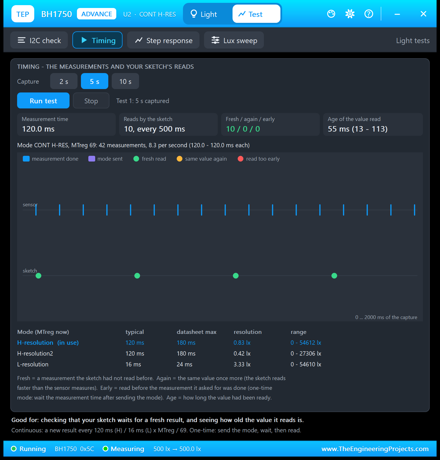
       Timing: Capture 5 s - 41 measurements of 120.0 ms, 10 reads every 500 ms,
         all fresh, the value 51 ms old on average (9 - 109 ms; 500 ms is not a
         multiple of 120). Type ONCE and MTREG 254 on U4 and capture again:
         441.7 ms per measurement, one mode write before every read, never too
         early, 7 reads every 674 ms, the value 231 ms old.
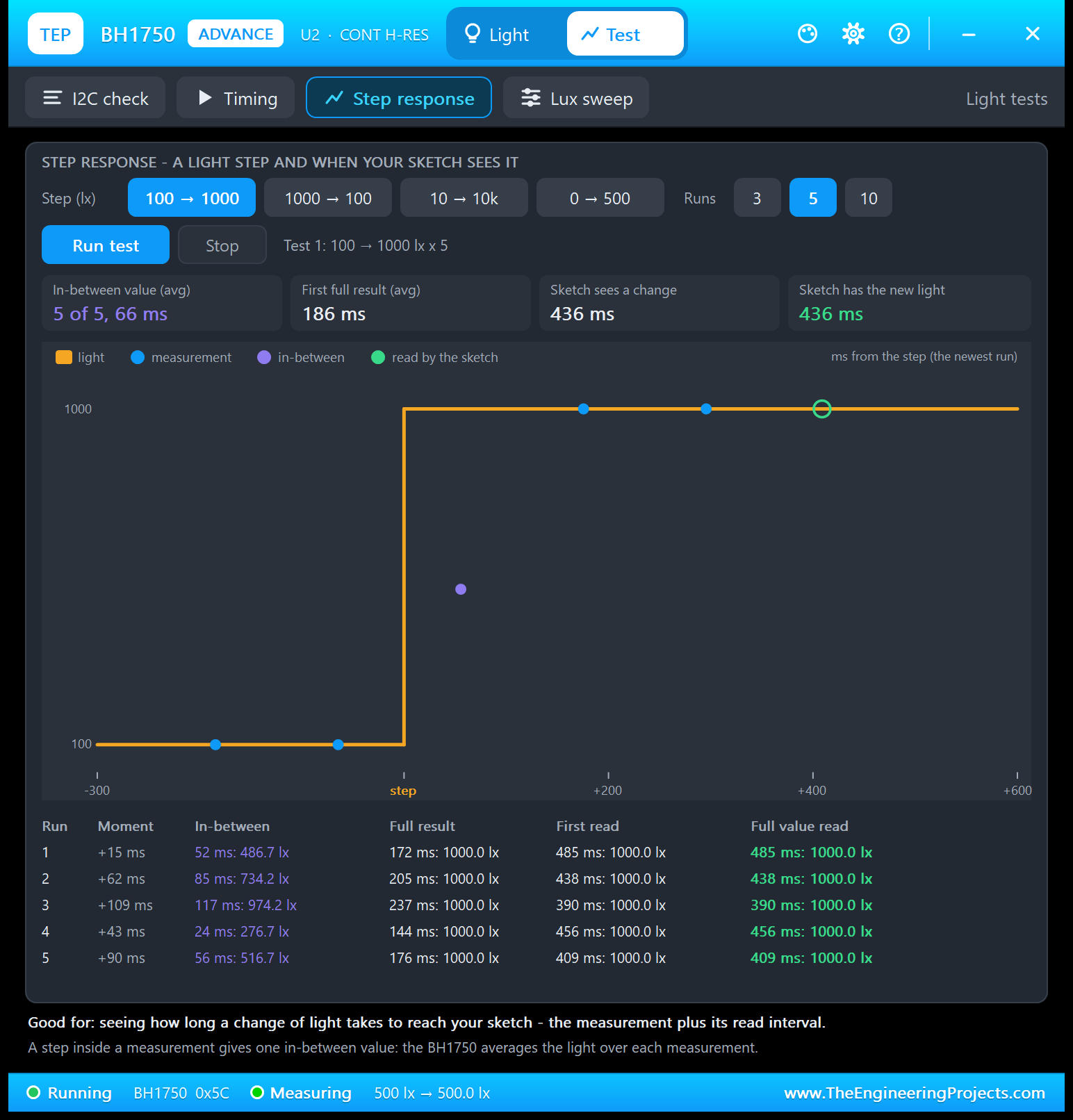
       Step response: 100 -> 1000 lx, 5 runs - an in-between value in every run
         (50 ms after the step on average), the first full result after 170
         ms, the sketch has the new light after 436 ms (its 500 ms reading
         interval).
       Lux sweep: Full 0.1 - 100k lx - 0.5 lx reads 0.8 lx (1 count), 60 and 100
         klx read the full scale 54612.5 lx (65535 counts), largest error 16.7 %
         (the 0.83 lx step at 1 lx); Dim 0 - 10 lx shows the steps; in
         H-resolution2 (MODE H2) the full scale is 27306 lx.
  5. Close U2's window and open it again with OPEN PANEL on the board.
Closed a monitor window? Click OPEN MONITOR on the monitor part.

WIRING (as in the v1.0 demo)
BH1750 VCC -> supply, GND -> GND, SCL -> A5, SDA -> A4, ADDR -> GND (address
0x23; open is 0x23 too) or -> VCC (0x5C).
In the sketch: Wire.begin(); lightMeter.begin(BH1750::CONTINUOUS_HIGH_RES_MODE,
0x23); lightMeter.readLightLevel(); Serial 9600.
The night-lamp LED + 220 ohm from A0 to GND on both UNOs.
Serial Monitor RXD <- Arduino D1 (TX), Serial Monitor TXD -> Arduino D0 (RX),
Serial Monitor GND -> ground. RXD2 is not needed: I2C has no serial line between
the sensor and the Arduino to watch.
In Proteus the UNO's Wire library uses its internal pull-ups on A4 / A5 (as in
the v1.0 demo); the model only pulls SDA LOW (open drain).
Pin order in Proteus: VCC GND SCL SDA ADDR (v1.0, the same order as on the
GY-302's header).
REAL HARDWARE:
 * Supply: VCC 3.3 V or 5 V - the GY-302 has a 3.3 V regulator (662K) and 4.7 k
   pull-ups on SCL / SDA; most boards work from a 5 V UNO directly (check yours -
   some sellers recommend a level shifter).
 * Address: ADDR LOW or open = 0x23, ADDR HIGH (>= 0.7 x VCC) = 0x5C - two
   sensors on one bus need one of each.
 * Accuracy: the datasheet gives 1.2 counts per lux typical, 0.96 - 1.44 - a real
   sensor can read up to 20 % high or low; calibrate against a known light meter
   (or set ACCURACY in the simulation to try it).
 * Range: 1 - 65535 counts = about 0.8 - 54612 lx in H-resolution at MTreg 69;
   direct sunlight (up to 100 klx) saturates it - use MTreg 31 (121557 lx) or put
   a diffuser in front of it.
 * The measurement time grows with MTreg: MTreg 254 = 442 ms (typ) / 663 ms (max).
 * 50 / 60 Hz light flicker averages out over a 120 ms H-resolution measurement;
   L-resolution (16 ms) does not average it (not simulated - the light is steady).

THE LIGHT
The slider and the scenes set the light that falls on the sensor (lux):
  DARK 0 (the slider's left stop)   NIGHT 1   ROOM 150   OFFICE 500
  OVERCAST 2000   SUN 30000; the slider 0.1 lx .. LUX_MAX on a log scale.
Properties LUX (at the start, default 100), LUX2 + STEP_TIME (a timed step, v1.0:
e.g. 100 -> 1000 lx at 3 s) also work as in v1.0; a slider / scene click
overrides the step for the rest of the run. Every new run starts again from LUX.
While a test tool runs it owns the light (the panel's slider waits).

THE TEST TOOLS (BH1750 Advance, Test tab) - what they really measure
Every tool runs on the live model with your sketch. A tool only sets the light
on the sensor and reads the sensor's own logs (the finished measurements and the
I2C transactions) - it never talks to your Arduino - so every time and value is
what your sketch and the sensor really did, measured with the simulation clock.
Each tool shows one "Good for:" line and one line on how it measures.
  I2C check       Good for: checking which commands your sketch really sends, to
                  which address, and how fast the clock is. Live: the address
                  and the ADDR pin, the SCL clock measured from the rising edges
                  (93.1 kHz in Proteus with Wire at 100 kHz), transactions to this
                  sensor and to other addresses, what the sketch sent (modes,
                  MTreg, power, reads, address probes, unknown opcodes), the
                  sketch's set-up (the first transactions after power-up,
                  decoded) and the last 16 transactions (W 23: 10 Continuously
                  H-resolution, R 23: 02 58 = 600 counts, W 5C: no ACK ...).
  Timing          Good for: checking that your sketch waits for a fresh result,
                  and seeing how old the value it reads is. Captures 2, 5 or 10 s:
                  the measurement time of the mode in use (measured: 120.0 ms in
                  H-resolution), measurements per second, the sketch's reads -
                  fresh (a measurement it had not read), the same value again (it
                  reads faster than the sensor measures) or too early (one-time
                  mode: read before the measurement it asked for was done) - and
                  the age of the value read; a 2 s timeline of measurements, mode
                  writes and reads; the typical / maximum time, resolution and
                  range of H, H2 and L at the MTreg in use. In Proteus with the
                  demo (5 s): 41 measurements of 120.0 ms, 10 reads every 500 ms,
                  10 / 0 / 0, 51 ms old (9 - 109); ONCE + MTreg 254: 441.7 ms, 7
                  reads every 674 ms, never early, 231 ms old.
  Step response   Good for: seeing how long a change of light takes to reach
                  your sketch - the measurement plus its read interval. Steps the
                  light (100 -> 1000, 1000 -> 100, 10 -> 10k or 0 -> 500 lx) 3, 5
                  or 10 times, each time at a different moment against the
                  measurements, after the sketch read a settled value: the
                  in-between measurement (the step inside it) with its value, the
                  first full measurement, the sketch's first read of a changed
                  value and its first read of the full new value - with a chart
                  of the newest run. In Proteus with the demo (100 -> 1000 lx x
                  5): an in-between value in 5 of 5 runs (50 ms after the step on
                  average), the first full result after 170 ms, the sketch had the
                  new light after 436 ms.
  Lux sweep       Good for: seeing the resolution and the range of your mode and
                  MTreg - and where the sensor saturates. Steps the light over Dim
                  0 - 10 lx, Indoor 0 - 1000 lx or Full 0.1 lx - 100 klx (log);
                  every point waits until the sketch read a full measurement made
                  at it (3 s at most): the counts, the lux the library makes of
                  them, the error, a chart of counts against light (the ideal 1.2
                  counts / lx line and, in the linear ranges, the sensor's steps),
                  the resolution and the full scale of the mode in use, and what
                  MTreg 31
…Development1 release
 Development1 release
-
V1.1BH1750 Light Sensor Library for Proteus V1.1this page
V1.1 is the only release in the Download Center so far. When a newer version is published, it appears above with its own download page.
Installation10 steps
 Installation10 steps
From the download to a working project, in order. The steps follow what the package contains.
You will need
- Proteus Design SuiteProteus 8 or newer (Labcenter), on Windows
- Arduino IDE1.8 or 2.x, with the board of the tutorial chosen under Tools → Board
- Any archive toolWindows, macOS and Linux extract ZIP files on their own
Steps
- 1
Extract the archive
Right-click bh1750-tep-v1-1-20ce9e1cf7b8435d95b28fdd71098a2d.zip and choose Extract All (or open it with 7-Zip or WinRAR) into a folder you can find again. Keep its folder structure (BH1750-TEP-v1.1) as it is.
- 2
Copy the library files into Proteus
Move ArduinoV3TEP.LIB, TEPBH1750.LIB and TEPSERIALMON.LIB and ArduinoV3TEP.IDX into the LIBRARY folder of your Proteus installation: C:\Program Files (x86)\Labcenter Electronics\Proteus 8 Professional\LIBRARY for Proteus 8, or the matching Proteus 7 folder. Older versions keep it under ProgramData\Labcenter Electronics. If Proteus is open, close it first.
- 3
Add the simulation model
Copy TEPBH1750.DLL and TEPSERIALMON.DLL into the MODELS folder next to LIBRARY, so the component can run, not only be drawn.
- 4
Restart Proteus and place the component
Start Proteus, open a schematic, press P (Pick Devices) and search for the component by the name used in the tutorial. It appears with its pins ready to wire.
- 5
Install the Arduino library
In the Arduino IDE choose Sketch → Include Library → Add .ZIP Library and pick the library, or copy its folder into Documents\Arduino\libraries. Restart the IDE to see its examples.
- 6
Open the sketch in the Arduino IDE
Open BH1750_Demo.ino, BH1750advanced.ino and BH1750autoadjust.ino and 3 more, select your board and port under Tools, then Verify. Sketch → Export Compiled Binary writes the HEX file a simulation needs.
- 7
Load the HEX file
In Proteus double-click the microcontroller, set Program File to BH1750_Demo.hex and run the simulation. For real hardware, flash the same file with your programmer.
- 8
Open the example simulation
Open BH1750-ArduinoUnoV3.pdsprj in Proteus to see the wiring exactly as in the tutorial. Check the controller's Program File path, then press Play.
- 9
Use the data files
library.json hold the readings or settings the project uses; open them with Excel, a text editor or the script of the tutorial.
- 10
Follow the tutorial
BH1750 Light Sensor Library for Proteus V1.1 (GY-302 + Arduino) explains every connection and setting in order; keep it open beside the files while you build.
FAQs9 questionsContact TEP
 FAQs9 questions
How do I download BH1750 Light Sensor Library for Proteus V1.1?
Wait for the 30-second guest countdown on this page, then press the download button; the file comes straight from our storage. Members who are logged in skip the wait. If the browser opens the file instead of saving it, use its Save as option. The download link is made for you when the countdown ends and works for 15 minutes; a saved or shared link stops working, so share this page instead.
What is inside the archive?
BH1750 Light Sensor Library for Proteus V1.1 comes as a ZIP archive of 25 files (1.4 MB, 3.0 MB unpacked) holding Proteus library files, simulation model DLLs, a Proteus simulation, an Arduino sketch, an Arduino library, compiled HEX firmware and data files. Open the File Structure tab for the full list of 25 files.
What should I do if the download does not start?
Check the browser's download list first; an ad blocker or a company firewall can also hold it back, so try another browser or network. If the file arrives incomplete, download it again. For an installation problem, read the Install tab or tell us in the comments with your software version and the exact error message.
Is this file free?
Yes. Every file in the TEP Download Center is free for learning, personal and student projects. If you share it, link back to this page or the tutorial so others find the latest version.
How do I check that the file arrived complete?
Compare its SHA-256 with the one on this page, c4903446a0200b4251a439b8600ec996faadb872b0d04268c5b003100d555b88. In PowerShell run Get-FileHash "bh1750-tep-v1-1-20ce9e1cf7b8435d95b28fdd71098a2d.zip"; on macOS or Linux run shasum -a 256 "bh1750-tep-v1-1-20ce9e1cf7b8435d95b28fdd71098a2d.zip". The same value means the file is exactly the one in our storage; a different one means the download broke off, so download it again.
Do I need WinRAR to open the ZIP file?
No. Windows, macOS and Linux open ZIP archives on their own (Extract All, or double-click). WinRAR and 7-Zip work too. Extract the whole archive before using the files.
Where do I put the LIB and IDX files?
Both files go into the LIBRARY folder of your Proteus installation (Proteus 8: C:\Program Files (x86)\Labcenter Electronics\Proteus 8 Professional\LIBRARY; Proteus 7 has the same folder under its own name). Restart Proteus afterwards and search for the component with P.
Which Proteus version does the library need?
The tutorial names the Proteus version the library was made and tested with. Most TEP libraries work in Proteus 7 and Proteus 8; if the component does not appear after a restart, check that both the LIB and the IDX file were copied and that Proteus was fully closed while copying.
How do I get the HEX file into the simulation?
Compile the sketch in the Arduino IDE (Sketch → Export Compiled Binary gives you the HEX next to the sketch), then in Proteus double-click the board, set Program File to that HEX and run.
Members skip the wait. Log in or join TEP.

- 15Total downloads
- 4%Popularity
- ProteusCategory
- 0Comments
- ssyedzainnasirUploaded by
- 27 Sep 2026Uploaded at


 SHA-256
c4903446a0200b4251a439b8600ec996faadb872b0d04268c5b003100d555b88


 Need help with this file?
 Tags
Related Proteus
All Proteus tutorials


Comments
0