


Project Files of nRF9151 DK Library for Proteus: LTE-M and GNSS Tracker Simulation
 Libraries
 Code
 Projects
 Simulation
b0cafc6d63304fe3aa793e025982c079.zip

nRF9151 DK Library for Proteus V1.0
nRF9151 DK Library for Proteus V1.0 comes as a ZIP archive of 288 files (3.6 MB, 8.0 MB unpacked) holding Proteus library files, simulation model DLLs, a Proteus simulation, an Arduino sketch, an Arduino library, compiled HEX firmware and source code.
- LIBProteus library
- DLLProteus model
- DSNProteus simulation
- INOArduino sketch
- LIBArduino library
- HEXHEX firmware
- SRCSource code
Description
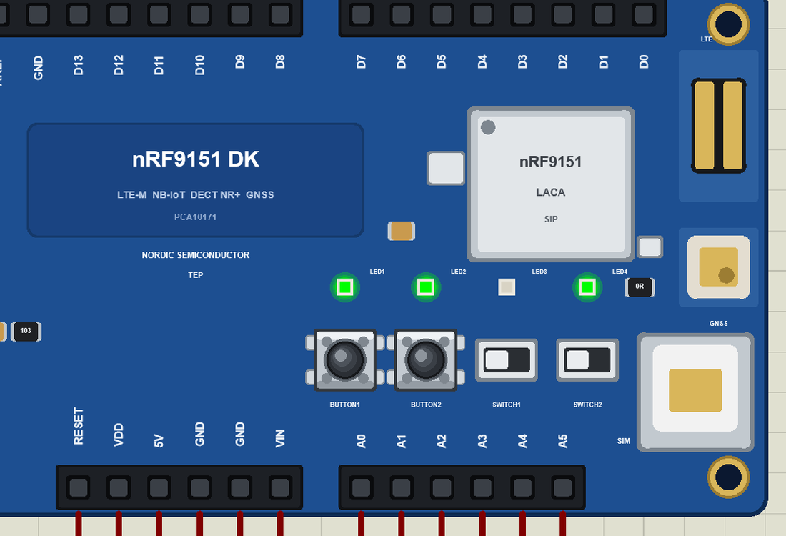
nRF9151-DK-Library-for-Proteus-v1.0.zip with the nRF9151 DK in Proteus (your sketch with the DK's pin names, four LEDs, two buttons, the LTE-M modem with SMS and GNSS on SerialModem, its Phone window and a serial monitor; TEPNRF9151DK.LIB, TEPNET.DLL and the TEP Boards for Proteus add-on 1.62.0), the BME280 library, the cold-chain tracker demo with its sketch and a README.

File Structure
 File Structure
9.6 KB1.1 KB7.7 KB11 KB8.5 KB1.5 KB1.7 KB1.9 KB5.7 KB4.9 KB1.1 KB5.8 KB9.6 KB7.2 KB2.5 KB2.1 KB1.9 KB2.1 KB4.4 KB1.1 KB3 KB3 KB1.8 KB2.5 KB3.5 KB149 B2.7 KB2 KB6.4 KB3.2 KB1.3 KB963 B8.6 KB5.9 KB6 KB12 KB1.6 KB1.3 KB14.7 KB4.3 KB6.1 KB20.1 KB8.2 KB2 KB4.5 KB311 B12.8 KB6.7 KB6.1 KB2.2 KB3.4 KB5.9 KB1.5 KB1.6 KB16.6 KB9.7 KB6.9 KB2.1 KB533 B5.7 KB7.4 KB514 B1.7 KB896 B481 B1.4 KB1012 B482 B936 B559 B467 B3.6 KB3.8 KB504 B956 B575 B455 B8.3 KB10.9 KB522 B79 B5.5 KB3.1 KB79 B442 B918 B1.4 KB1.8 KB1 KB1.3 KB1.4 KB1.8 KB1.4 KB5.7 KB502 B463 B5 KB6.5 KB3.4 KB3.4 KB500 B1.6 KB368 B406 B466 B404 B444 B460 B477 B739 B448 B1.3 KB350 B5.7 KB4 KB562 B1.5 KB2 KB550 B7.2 KB4.1 KB371 B4.5 KB3.5 KB492 B390 B478 B6.6 KB2.4 KB479 B5.1 KB1.9 KB1.3 KB1.3 KB750 B1.3 KB490 B2.2 KB1.9 KB498 B1.2 KB1.2 KB487 B5.1 KB4.6 KB371 B1.5 KB1.2 KB478 B6.2 KB3 KB1.5 KB1.7 KB469 B1 KB1.7 KB433 B294 B358 B1.3 KB2.5 KB13.2 KB3.8 KB659 B510 B4.4 KB1.9 KB5.8 KB11 KB835 B518 B6.4 KB2.3 KB29 B436 B9.2 KB4.9 KB439 B4.2 KB1.5 KB9.3 KB7.1 KB4.7 KB2.4 KB388 B5.1 KB893 B667 B1.3 KB5.5 KB2.3 KB1.8 KB468 B882 B530 B791 B487 B894 B2 KB730 B646 B2.6 KB977 B702 B20.6 KB1.8 KB11.8 KB3.2 KB596 B406 B6.3 KB5.7 KB9.3 KB7.7 KB7.7 KB5.8 KB5.9 KB6.4 KB6.4 KB5.3 KB5.6 KB5.7 KB7.9 KB7.7 KB6.5 KB6.3 KB6.2 KB10.3 KB8.5 KB6.6 KB7.6 KB6.7 KB6.1 KB6.7 KB8.3 KB6.2 KB7.2 KB5.9 KB5.6 KB5.7 KB6.7 KB5.9 KB6.2 KB6 KB6 KB6.1 KB6.3 KB6 KB6.1 KB6.2 KB6 KB5.8 KB6.4 KB6.4 KB6.9 KB6.8 KB7 KB6.5 KB6.6 KB6.5 KB5.6 KB7.5 KB7.7 KB7.1 KB5.8 KB5.9 KB5.9 KB6.9 KB5.5 KB5.5 KB7.1 KB5.2 KB30.3 KB25.9 KB1.3 KB8.5 KB34.7 KB89.4 KB39.5 KB13.1 KB38.5 KB381 KB2.9 MB66.8 KB20.4 KB381 KB2.9 MB12.5 KBGallery12 images from the tutorialOpen the tutorial
 Gallery12 images from the tutorial
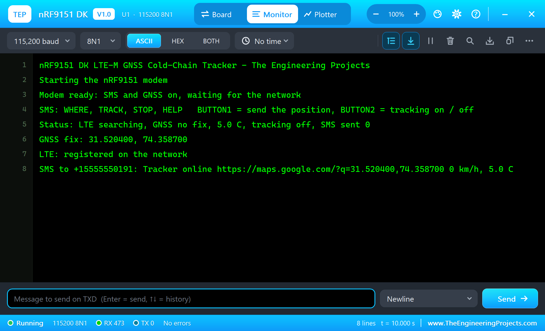
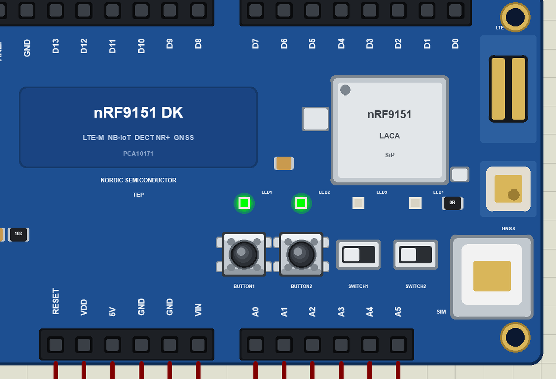
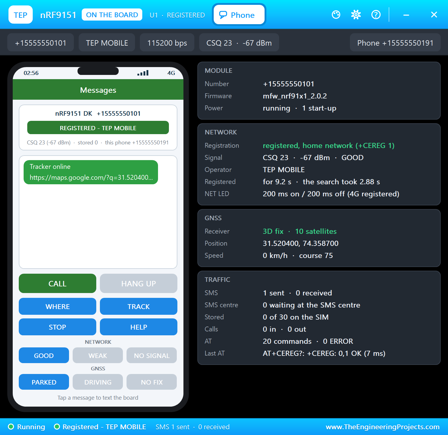
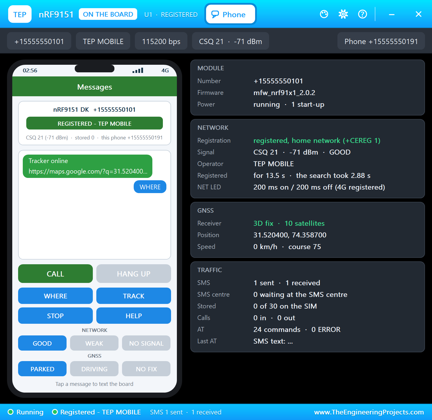
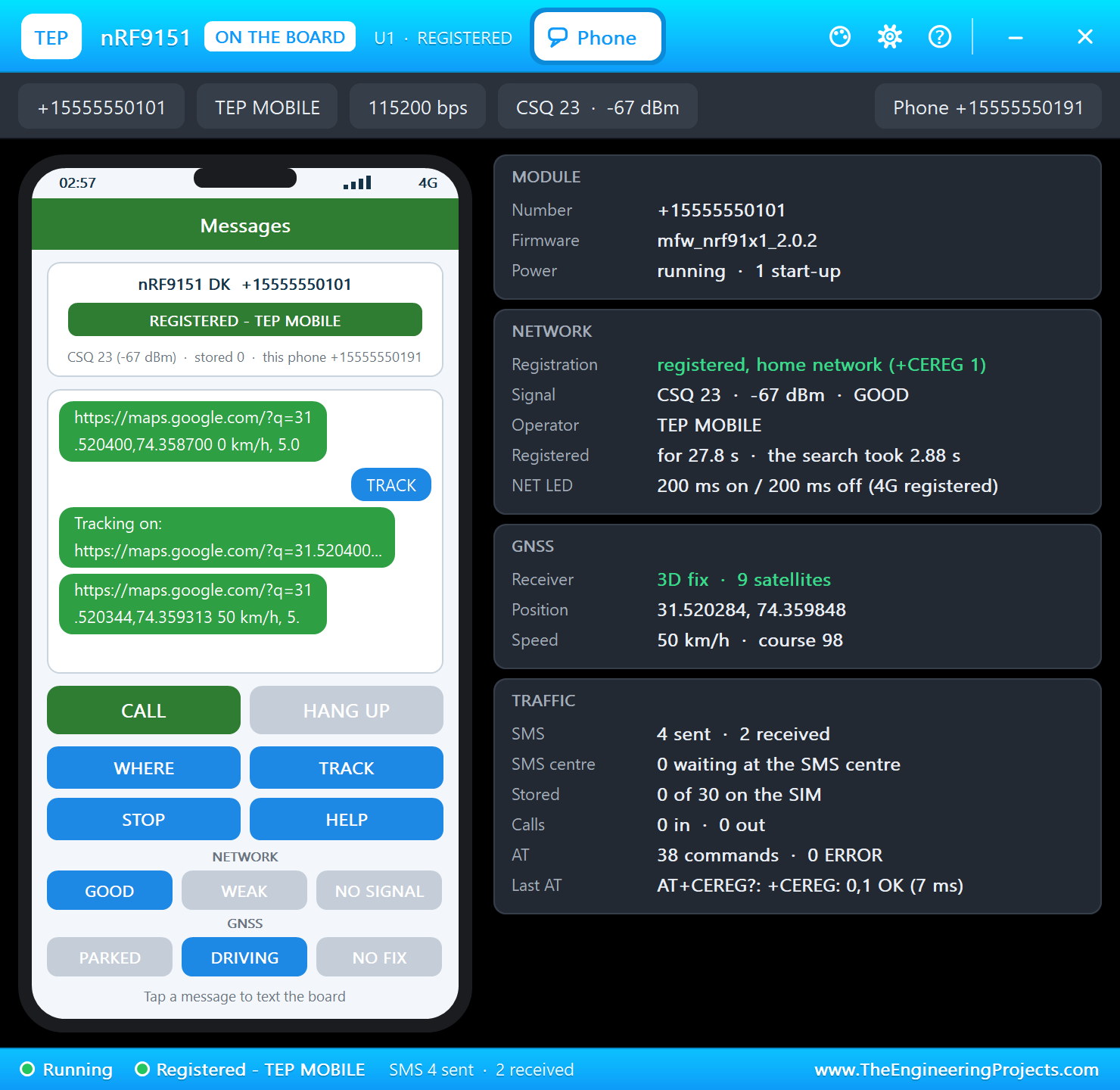
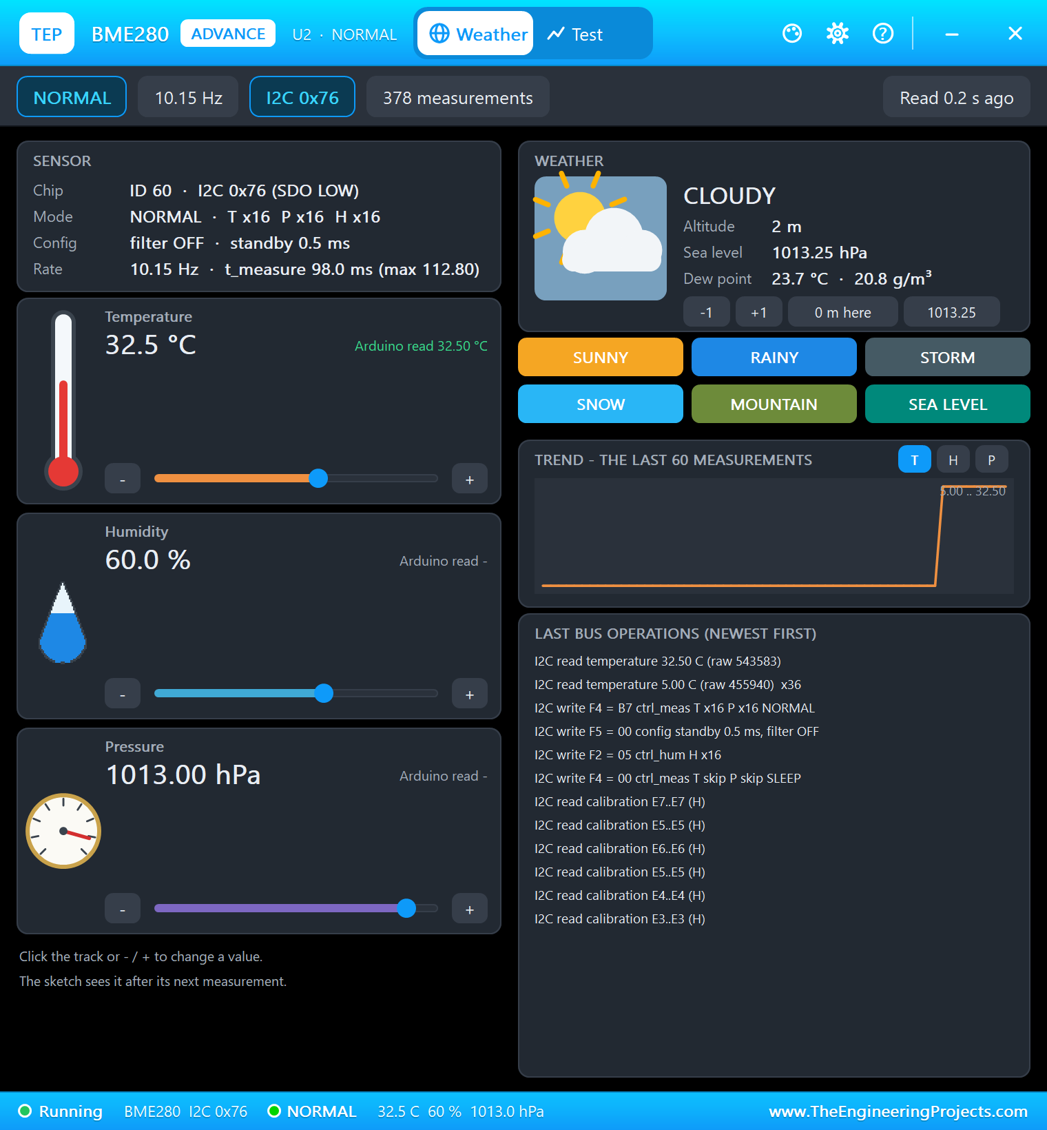
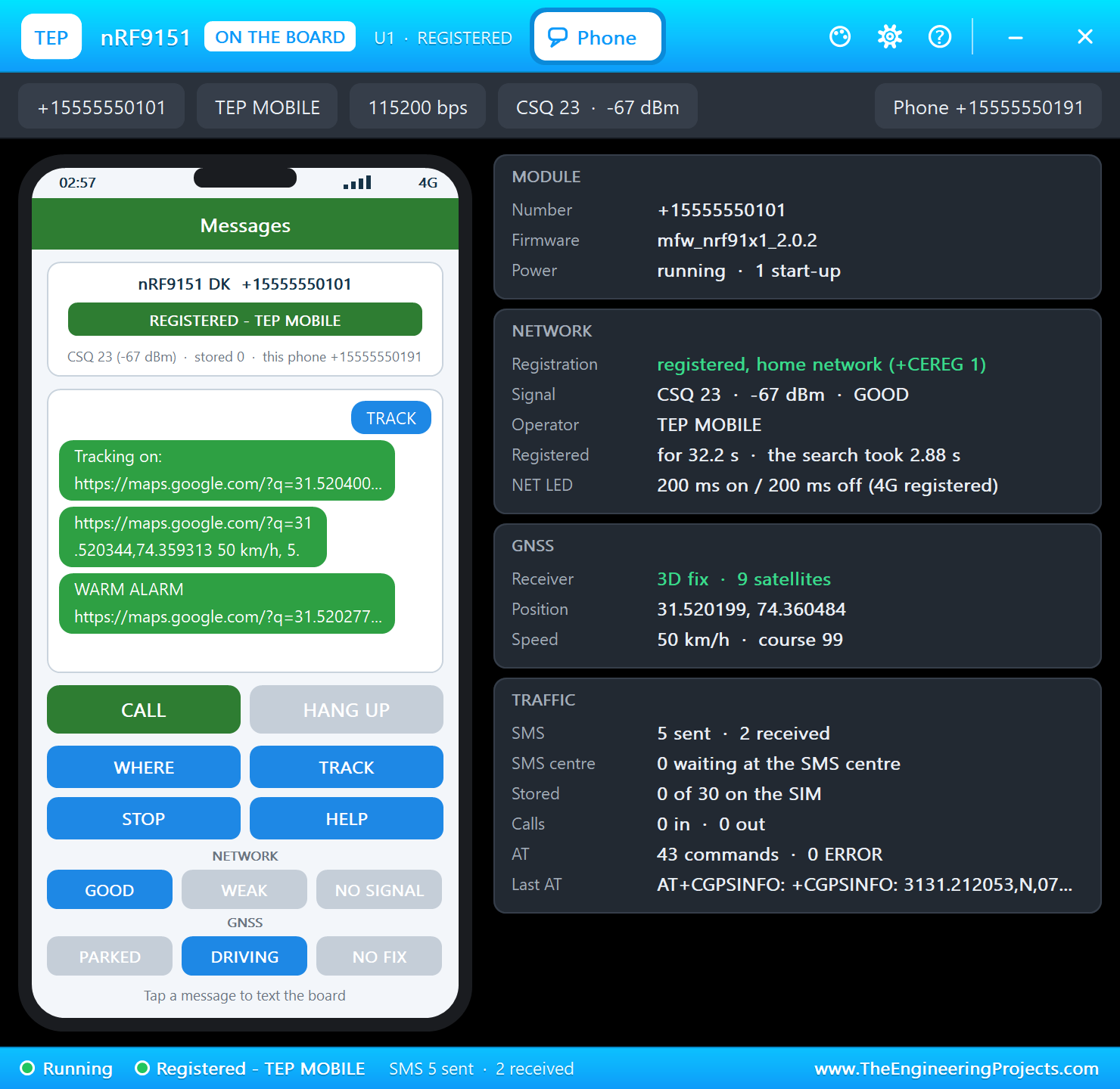
The circuit, the board and the results as they appear in nRF9151 DK Library for Proteus: LTE-M and GNSS Tracker Simulation. Open an image for its full size.
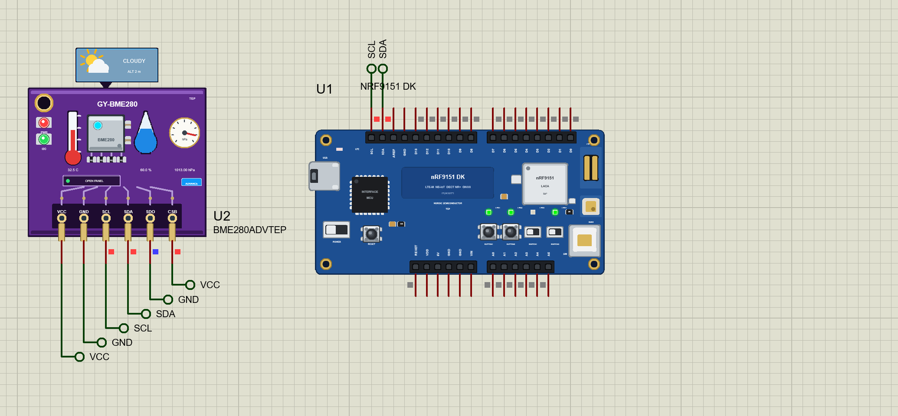
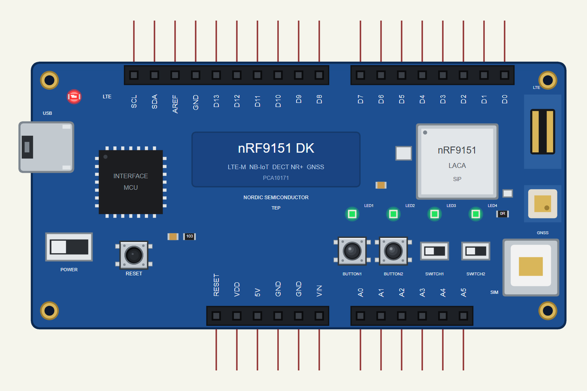
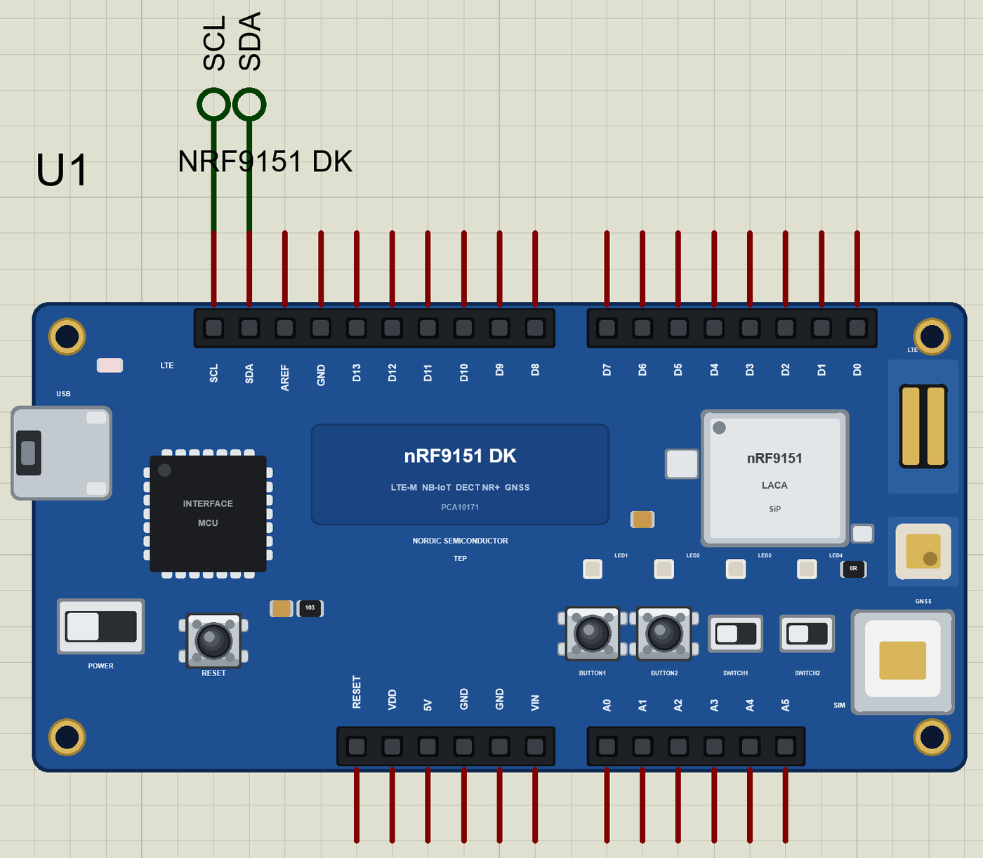
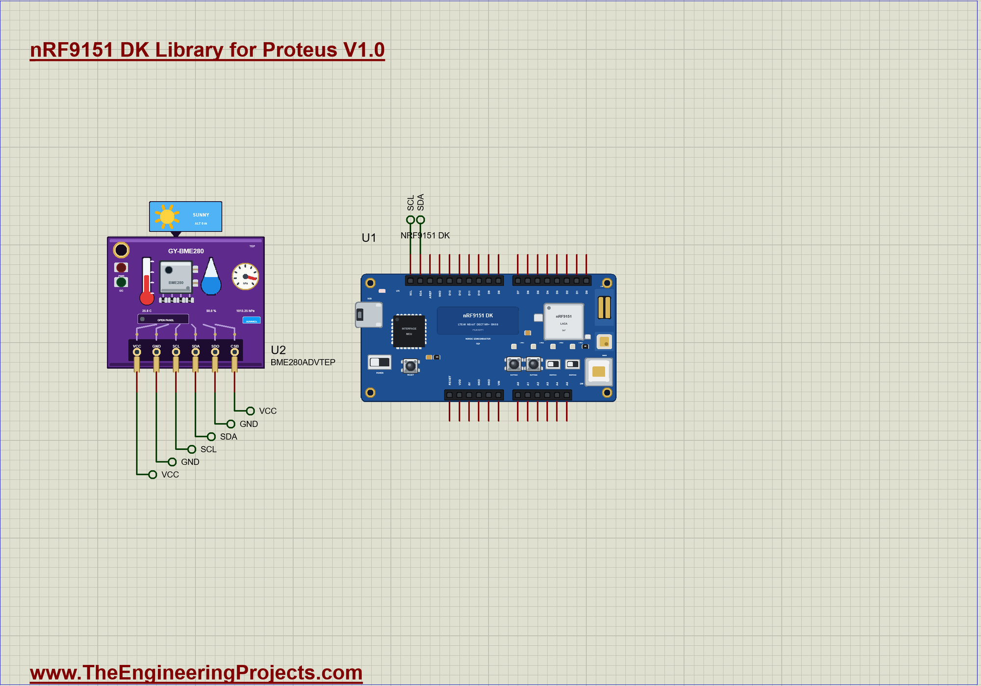
README
 README
NRF9151 DK LIBRARY FOR PROTEUS - V1.0 (YOUR ARDUINO SKETCH, THE LTE-M / NB-IOT MODEM WITH SMS AND GNSS, FOUR LEDS)
Designed by The Engineering Projects
www.TheEngineeringProjects.com

IMPORTANT LINKS
Article (read it first - pictures, step by step, every feature explained):
  https://www.theengineeringprojects.com/2026/11/nrf9151-dk-library-for-proteus.html
Report a bug or suggest a feature (our forum):
  https://www.theengineeringprojects.com/forum
The demo's other part is our library (included) - its article:
  https://www.theengineeringprojects.com/2026/09/bme280-sensor-library-for-proteus.html
Support us (the libraries are free):
  https://www.theengineeringprojects.com/donate

FILE STRUCTURE
nRF9151-DK-TEP-v1.0/
|-- Proteus Library Files/
|   |-- TEPBME280.LIB                                    89.4 KB   the BME280 (demo), to LIBRARY
|   |-- TEPLAPTOP.LIB                                    39.5 KB   the laptop (demo), to LIBRARY
|   |-- TEPMOBILE.LIB                                    13.1 KB   the phone (demo), to LIBRARY
|   |-- TEPNRF9151DK.LIB                                 38.5 KB   the nRF9151 DK, to LIBRARY
|-- Proteus Model Files/
|   |-- TEPBME280.DLL                                   381.0 KB   the BME280, to MODELS
|   |-- TEPNET.DLL                                       2.91 MB   the board + monitors + network, to MODELS
|-- Arduino Code/
|   |-- DK_LTE_GNSS_Tracker/DK_LTE_GNSS_Tracker.ino       9.6 KB   the demo sketch
|   |-- TEP Boards for Proteus/hardware/                 1.13 MB   the Arduino IDE add-on 1.62.0 (276 files)
|-- Proteus Simulation/
|   |-- DK_LTE_GNSS_Tracker.hex                          66.8 KB   the demo sketch (U1)
|   |-- nRF9151-DK-LTE-GNSS-Tracker.pdsprj               20.4 KB   the demo: an LTE-M GNSS cold-chain tracker
|   |-- TEPBME280.DLL                                   381.0 KB   copy of the model
|   |-- TEPNET.DLL                                       2.91 MB   copy of the model
|-- README.txt                                          ~12.1 KB   this file
Total: 7.97 MB (unzipped). The source code of the models is not included.

WHAT IS IT?
Proteus 8 has no nRF9151 processor model, so this is NOT a real nRF9151 chip. Our team has put a lot of effort into
building this board ourselves: it is Nordic Semiconductor's nRF9151 DK (PCA10171) - the blue development kit with the
nRF9151 SiP (system-in-package: the processor, the LTE-M / NB-IoT / DECT NR+ modem and GNSS under one shield), the
nano-SIM holder, the LTE and GNSS antennas, the interface MCU with its USB port, the power switch, four green LEDs, two
buttons and two slide switches - drawn compact, and it runs YOUR Arduino sketch in Proteus:
  * You write a normal sketch for the DK's Arduino header (D0 .. D13, A0 .. A5, SDA, SCL; analogRead 0-1023,
    analogWrite, attachInterrupt, tone, Wire, SPI, Serial) and compile it in the Arduino IDE with our board package
    "TEP Boards for Proteus" 1.62.0 (in Arduino Code - see INSTALLATION).
  * The modem answers AT commands on SerialModem (115200 baud): registration (AT+CEREG?), SMS in text mode (AT+CMGF=1,
    AT+CMGS, AT+CNMI and +CMT), and GNSS (AT+CGPS=1,1, AT+CGPSINFO). MODEM_ON HIGH starts it. On the real chip the
    application starts the modem with Nordic's modem library and sends the same kind of AT commands through it.
  * The board's Phone window is the other end: the owner's phone receives the board's SMS, sends SMS (with four quick
    keys: WHERE, TRACK, STOP, HELP) and sets the network and the GNSS scene (parked, driving, no fix).
  * LED1 .. LED4 light when HIGH, as on the real DK (LED_BUILTIN is LED1). BUTTON1 / BUTTON2 read LOW while you hold
    them: click a button on the board in the running simulation.
TEP additions: the USB port opens the serial monitor (the same window as our TEP Serial Monitor Advance); the small
LTE LED shows the modem's network light (its blink changes when the modem registers); a click on
the SiP opens the modem's window.
Limits (say them before you start): there is no Bluetooth on the nRF9151. Voice calls, data (IP, MQTT, CoAP), DECT NR+,
PSM and eDRX timers are not modelled; SMS is text mode only. SWITCH1 / SWITCH2 are drawn, not modelled.
Your sketch gets 8 KB of RAM in the simulation (the real one: 256 KB), about 256 KB of flash, and int is 16 bits in
the simulation (use long for big numbers). See MODEL SCOPE AND LIMITS.

ONE DEVICE (search "NRF9151" in Pick Devices):
  NRF9151 DK  "nRF9151 DK" V1.0 (Microprocessor ICs > Cellular Boards), prefix U, model TEPNET.DLL.
  Its TEP windows have no Windows title bar: the serial monitor (the USB port, 115200 baud: Monitor, Plotter and Board
  tabs) and the modem's window (a click on the SiP).
The same TEPNET.DLL also runs our other sketch boards and the phone; it replaces any older TEPNET.DLL (keep only this
newest one in MODELS).

TEST STATUS
V1.0: verified in Proteus 8.5 on 17 Nov 2026 with the demo project as shipped. What the Proteus run showed:
* nRF9151-DK-LTE-GNSS-Tracker: "Starting the nRF9151 modem", "Modem ready: SMS and GNSS on, waiting for the network";
  the LTE LED blinked while the modem searched. "GNSS fix: 31.520400, 74.358700" (the GNSS scene starts PARKED), LED2
  on; "LTE: registered on the network" (registered in 2.9 s), LED1 on; the SMS "Tracker online" with the map link,
  0 km/h and 5.0 C reached the Phone window.
* WHERE from the phone: "SMS from +15555550191: WHERE" and the answer with the map link. TRACK: "tracking ON (a
  position every 30 s)", LED4 on, and "Tracking on: ..." on the phone.
* GNSS scene DRIVING, BUTTON1: the moving position at 50 km/h by SMS.
* The BME280's pop-up, a warm load: ">> WARM: 32.5 C" and the SMS "WARM ALARM" with the position and 32.5 C.
* BUTTON2: "tracking OFF", LED4 off. GNSS scene NO FIX: "GNSS: no fix", LED2 off; LED1 stayed on.
* about 46 s of simulation, no errors, with the Phone window, the BME280's window and the monitor open.

INSTALLATION (about 3 minutes)
1. Close Proteus. Extract the WHOLE ZIP to a normal folder (e.g. Desktop).
2. Copy everything in "Proteus Library Files" to the LIBRARY folder of Proteus, for example:
     C:\Program Files (x86)\Labcenter Electronics\Proteus 8 Professional\LIBRARY
   (on some PCs: C:\ProgramData\Labcenter Electronics\Proteus 8 Professional\LIBRARY). TEPNRF9151DK.LIB is the board;
   the others: TEPBME280.LIB (the demo's sensor), TEPMOBILE.LIB and TEPLAPTOP.LIB (for your own designs).
3. Copy the DLLs from "Proteus Model Files" (TEPNET.DLL, TEPBME280.DLL) to the MODELS folder
   (...\Proteus 8 Professional\MODELS) -
   replace an older TEPNET.DLL (this one is the first that knows this board).
4. Delete TEPNRF9151DK.IDX from the LIBRARY folder if it is there.
5. The Arduino IDE (only to compile your own sketches - the demo has its HEX file): copy the folder
   "Arduino Code\TEP Boards for Proteus\hardware" into your sketchbook folder (normally Documents\Arduino), so that
   Documents\Arduino\hardware\tep\avr\boards.txt exists (replace an older copy); restart the IDE. The Arduino AVR Boards
   platform must be installed (it comes with IDE 1.8.x; in IDE 2.x install "Arduino AVR Boards" from the Boards
   Manager once).
   Tools > Board > TEP Boards for Proteus > Nordic nRF9151 DK (TEP Proteus). From the Library Manager: Adafruit BME280
   and Adafruit Unified Sensor.
6. Start Proteus. In Pick Devices (P) search "NRF9151".

RUN THE DEMO
Keep the .hex file and the DLLs beside the project in "Proteus Simulation".
nRF9151-DK-LTE-GNSS-Tracker.pdsprj - U1 the nRF9151 DK (DK_LTE_GNSS_Tracker.hex) is a cellular cold-chain tracker:
U2 = the BME280 (Advance) on the I2C header (SDA, SCL) measures the load (5 C at the start); the owner's phone is the
board's own Phone window (it opens at Run).
Press Run. The monitor prints "Starting the nRF9151 modem", then "Modem ready"; the LTE LED blinks while the modem
searches. The GNSS scene starts PARKED: "GNSS fix" lights LED2. "LTE: registered on the network" lights LED1, and the
board sends "Tracker online" with a map link and the temperature (LED3 lights while an SMS goes out).
In the Phone window press WHERE: the board answers with the map link. TRACK: a position every 30 s, LED4 on; STOP ends
it. On the board, BUTTON1 sends the position at once and BUTTON2 switches tracking on / off. DRIVING makes the
position move; NO FIX turns LED2 off. On the BME280's pop-up click the Temperature track above 8 C: a WARM ALARM SMS.
Closed a window? The USB port opens the monitor, the SiP the Phone window, the OPEN PANEL pad the BME280.

THE PINS (the label on the part, what it can do in the simulation)
  D0, D1          GPIO (Serial1 is the modem's AT interface: SerialModem)
  D2 .. D13       GPIO, PWM (analogWrite), interrupt; D10 .. D13 SPI (SS, MOSI, MISO, SCK)
  A0 .. A5        analogRead 0 .. 1023 for 0 .. 3.3 V, or GPIO (the core's numbers 14 .. 19)
  SDA, SCL        Wire
  VDD, 5V, GND    3.3 V (the logic), 5 V, ground;   RESET  the board's reset (the RESET button too)
  AREF, VIN       drawn, not modelled
LED1 .. LED4 (22 .. 25) are the green LEDs, lit when HIGH; LED_BUILTIN is LED1, with LED_BUILTIN_ACTIVE and
LED_BUILTIN_INACTIVE. BUTTON1 / BUTTON2 (26 / 27) are the buttons, LOW when pressed (pinMode INPUT_PULLUP);
BTN_BUILTIN is BUTTON1. MODEM_ON (30) starts the modem. Serial is the USB: the board's built-in monitor. The real
board's LEDs are P0.00 P0.01 P0.04 P0.05, its buttons P0.08 P0.09 and its switches P0.18 P0.19.

PROPERTIES (double-click the part > Edit Properties)
  PROGRAM      the sketch's HEX (Arduino IDE: Sketch > Export Compiled Binary, board Nordic nRF9151 DK (TEP Proteus))
  MONITOR      YES = the built-in serial monitor on Serial;  BAUD  its speed (115200, or AUTO)
  AUTOOPEN     YES = the monitor window opens at Run (the demo: YES)

TROUBLESHOOTING
* The modem never answers: set MODEM_ON HIGH and SerialModem.begin(115200) first; send AT until it answers OK.
* No SMS arrives: AT+CMGF=1 (text mode) and AT+CNMI=2,2,0,0,0 make a new SMS come straight to SerialModem as +CMT.
* "No GNSS fix yet": turn GNSS on with AT+CGPS=1,1 and set the phone's GNSS scene to PARKED or DRIVING.
* The LEDs look inverted: on this DK they light when the pin is HIGH.
* An integer goes wrong above 32767: int is 16 bits in the simulation - use long.

BUG REPORTS AND FEATURE REQUESTS
Please post them in our forum with a screenshot and the Serial Monitor text:
  https://www.theengineeringprojects.com/forum

LICENCES AND THIRD-PARTY NOTES
* The board model (TEPNET.DLL, with its modem), the symbols and artwork (TEPNRF9151DK.LIB) and the BME280 model are
  made by The Engineering Projects. The source code of the models is not included.
* TEP Boards for Proteus (Arduino Code): its core, the variants and the EEPROM, SPI and Wire libraries are modified
  copies of the Arduino AVR core 1.8.6 - GNU Lesser General Public License 2.1 (LGPL 2.1, the text:
  LICENSE-LGPL-2.1.txt); its WiFi, WebServer, ArduinoBLE, the sensor libraries and the others and our core files are
  MIT (LICENSE-MIT.txt).
* The demo sketch uses Adafruit BME280 and Adafruit Unified Sensor (BSD, Apache 2.0): install them with the Library
  Manager to rebuild.
* Proteus is a product of Labcenter Electronics and is not included. nRF9151 and Nordic Semiconductor are names of
  Nordic Semiconductor ASA, Arduino of Arduino. This library is not made or endorsed by them or by Labcenter.

REBUILDING THE FIRMWARE (OPTIONAL)
The HEX file is supplied. Install TEP Boards for Proteus (INSTALLATION step 5), open Arduino
Code\DK_LTE_GNSS_Tracker, select Nordic nRF9151 DK (TEP Proteus) and use Sketch > Export Compiled Binary. For a real
board use Nordic's nRF Connect SDK with its modem library, SMS library and GNSS interface; a SIM with an LTE-M or
NB-IoT plan is needed. Its pins work at 1.8 or 3.3 V.

MODEL SCOPE AND LIMITS
Modelled: the DK's Arduino header; digital I/O, analogRead 0 .. 1023, PWM (analogWrite), tone and attachInterrupt
through the board model; Serial (the board's monitor), Wire and SPI; the four LEDs, the two buttons and RESET; the
modem's AT interface with registration, SMS (text mode) and GNSS, with the phone as the other end.
Not modelled: the nRF9151 itself, the radio and its coverage, data connections (IP, MQTT, CoAP), DECT NR+, voice,
PSM and eDRX, the SIM's PIN, SWITCH1 / SWITCH2, the current measurement header. The simulation runs below real time.

VERSION
TEP nRF9151 DK library V1.0 (Nov 2026). Device NRF9151 DK (TEPNRF9151DK.LIB / TEPNET.DLL), TEP Boards for Proteus
1.62.0 (adds this board: LED1 .. LED4, BUTTON1 / BUTTON2, SerialModem, MODEM_ON).
Demo sketch DK_LTE_GNSS_Tracker V1.0. Demo part: BME280ADVTEP.Development1 release
 Development1 release
-
V1.0nRF9151 DK Library for Proteus V1.0this page
V1.0 is the only release in the Download Center so far. When a newer version is published, it appears above with its own download page.
Installation10 steps
 Installation10 steps
From the download to a working project, in order. The steps follow what the package contains.
You will need
- Proteus Design SuiteProteus 8 or newer (Labcenter), on Windows
- Arduino IDE1.8 or 2.x, with the board of the tutorial chosen under Tools → Board
- The compiler named in the tutorialto build the source files into firmware
- Any archive toolWindows, macOS and Linux extract ZIP files on their own

Steps
- 1
Extract the archive
Right-click b0cafc6d63304fe3aa793e025982c079.zip and choose Extract All (or open it with 7-Zip or WinRAR) into a folder you can find again. Keep its folder structure (nRF9151-DK-TEP-v1.0) as it is.
- 2
Copy the library files into Proteus
Move TEPBME280.LIB, TEPLAPTOP.LIB and TEPMOBILE.LIB and 1 more and the files into the LIBRARY folder of your Proteus installation: C:\Program Files (x86)\Labcenter Electronics\Proteus 8 Professional\LIBRARY for Proteus 8, or the matching Proteus 7 folder. Older versions keep it under ProgramData\Labcenter Electronics. If Proteus is open, close it first.
- 3
Add the simulation model
Copy TEPBME280.DLL and TEPNET.DLL into the MODELS folder next to LIBRARY, so the component can run, not only be drawn.
- 4
Restart Proteus and place the component
Start Proteus, open a schematic, press P (Pick Devices) and search for the component by the name used in the tutorial. It appears with its pins ready to wire.
- 5
Install the Arduino library
In the Arduino IDE choose Sketch → Include Library → Add .ZIP Library and pick the library, or copy its folder into Documents\Arduino\libraries. Restart the IDE to see its examples.
- 6
Open the sketch in the Arduino IDE
Open DK_LTE_GNSS_Tracker.ino, eeprom_clear.ino and eeprom_crc.ino and 17 more, select your board and port under Tools, then Verify. Sketch → Export Compiled Binary writes the HEX file a simulation needs.
- 7
Build the source code
Open abi.cpp, Arduino.h and binary.h and 52 more in the compiler named in the tutorial (MikroC, Keil, MPLAB, Code Composer or the Arduino IDE) and build it to get the firmware.
- 8
Load the HEX file
In Proteus double-click the microcontroller, set Program File to DK_LTE_GNSS_Tracker.hex and run the simulation. For real hardware, flash the same file with your programmer.
- 9
Open the example simulation
Open nRF9151-DK-LTE-GNSS-Tracker.pdsprj in Proteus to see the wiring exactly as in the tutorial. Check the controller's Program File path, then press Play.
- 10
Follow the tutorial
nRF9151 DK Library for Proteus: LTE-M and GNSS Tracker Simulation explains every connection and setting in order; keep it open beside the files while you build.
FAQs9 questionsContact TEP
 FAQs9 questions
How do I download nRF9151 DK Library for Proteus V1.0?
Wait for the 30-second guest countdown on this page, then press the download button; the file comes straight from our storage. Members who are logged in skip the wait. If the browser opens the file instead of saving it, use its Save as option. The download link is made for you when the countdown ends and works for 15 minutes; a saved or shared link stops working, so share this page instead.
What is inside the archive?
nRF9151 DK Library for Proteus V1.0 comes as a ZIP archive of 288 files (3.6 MB, 8.0 MB unpacked) holding Proteus library files, simulation model DLLs, a Proteus simulation, an Arduino sketch, an Arduino library, compiled HEX firmware and source code. Open the File Structure tab for the full list of 288 files.
What should I do if the download does not start?
Check the browser's download list first; an ad blocker or a company firewall can also hold it back, so try another browser or network. If the file arrives incomplete, download it again. For an installation problem, read the Install tab or tell us in the comments with your software version and the exact error message.
Is this file free?
Yes. Every file in the TEP Download Center is free for learning, personal and student projects. If you share it, link back to this page or the tutorial so others find the latest version.
How do I check that the file arrived complete?
Compare its SHA-256 with the one on this page, 8d8ae7705108f5fd3a84c312074ab65d89bb3e3cf20df1cd81029d348d0ec5d6. In PowerShell run Get-FileHash "b0cafc6d63304fe3aa793e025982c079.zip"; on macOS or Linux run shasum -a 256 "b0cafc6d63304fe3aa793e025982c079.zip". The same value means the file is exactly the one in our storage; a different one means the download broke off, so download it again.
Do I need WinRAR to open the ZIP file?
No. Windows, macOS and Linux open ZIP archives on their own (Extract All, or double-click). WinRAR and 7-Zip work too. Extract the whole archive before using the files.
Where do I put the LIB and IDX files?
Both files go into the LIBRARY folder of your Proteus installation (Proteus 8: C:\Program Files (x86)\Labcenter Electronics\Proteus 8 Professional\LIBRARY; Proteus 7 has the same folder under its own name). Restart Proteus afterwards and search for the component with P.
Which Proteus version does the library need?
The tutorial names the Proteus version the library was made and tested with. Most TEP libraries work in Proteus 7 and Proteus 8; if the component does not appear after a restart, check that both the LIB and the IDX file were copied and that Proteus was fully closed while copying.
How do I get the HEX file into the simulation?
Compile the sketch in the Arduino IDE (Sketch → Export Compiled Binary gives you the HEX next to the sketch), then in Proteus double-click the board, set Program File to that HEX and run.
Members skip the wait. Log in or join TEP.

- 0Total downloads
- 4%Popularity
- ProteusCategory
- 0Comments
- ssyedzainnasirUploaded by
- 19 Nov 2026Uploaded at


 SHA-256
8d8ae7705108f5fd3a84c312074ab65d89bb3e3cf20df1cd81029d348d0ec5d6


 Need help with this file?
 Tags
Related Proteus
All Proteus tutorials





Comments
0