


How to Design a New Component in Proteus: Plan Before You Draw


Hello friends, I hope you are doing well. This is the second tutorial in our series on how to create a Proteus library. In the previous tutorial, How to Create a Proteus Library: How It Works Behind the Scenes, we looked at what a library part is made of: the symbol, the pins, the properties, the package, the index and the simulation model, and at what Proteus does with them when you press Run. Today, we start building our own part, and we start the way every good component starts: on paper, before the first line is drawn. Our topic is how to design a new component in Proteus.
Our running example is a Traffic Light Module, a small board with a red, a yellow and a green lamp that an Arduino switches through three pins. In this tutorial, we will decide what the component must do, choose between a plain box symbol and a realistic module drawing, learn the units, grid and snap settings of Proteus, fix the size and position of every shape, plan the pins with their names, numbers and electrical types, choose the colours, split the drawing into layers and plan the animation states. At the end, we will have a complete design plan that the next tutorials follow step by step.
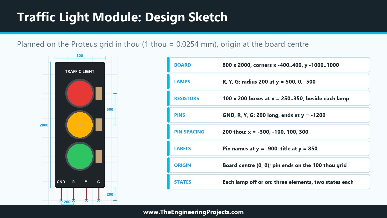
The module we model is a common Arduino accessory, and its pins and behaviour are taken from published descriptions of it. The Proteus menus and shortcuts in this tutorial were checked in Proteus 8.5 Professional on our own PC. The picture below is the design sketch we are going to build in this tutorial: every number on it is explained in the sections that follow.
What Are We Going to Build?
A traffic light module is a small board with three LEDs, one red, one yellow and one green, arranged like a road traffic light. It is popular for Arduino lessons because it turns the classic traffic light exercise into a single plug-in part. Published descriptions of the module agree on its main features:
- It has four pins: GND, R, Y and G. GND goes to the ground of the Arduino, and R, Y and G each go to a digital output.
- A pin set HIGH turns its lamp on, and a pin set LOW turns it off. The Arduino example for the module simply writes HIGH and LOW to pins 2, 3 and 4.
- The LEDs are wired as common cathode: all negative terminals meet at the GND pin, and each positive terminal has its own pin.
- The board carries a series resistor for each LED, so it can be driven straight from a microcontroller pin. One description gives about 330 ohm for red, 220 ohm for yellow and 470 ohm for green; boards from other makers may use other values.
- It works from 3.3 V to 5 V logic.
Our Proteus version keeps exactly these four pins and this behaviour, so that a sketch written for the real module works in the simulation unchanged. On the screen, it will look like a small black board with three round lamps that light up while the simulation runs. This is a deliberately simple part: it has no communication protocol and no timing to model, which lets us concentrate on the library mechanics. Everything we learn with it applies to bigger parts as well.
Why Plan a Proteus Component Before Drawing It?
It is tempting to open Proteus, draw a box, add a few pins and press Make Device. For a quick schematic symbol that is fine. For a library part that other people will use, a few minutes of planning save hours later, for three reasons.
- Pins are hard to change later. Every design that uses the part depends on the position, name and number of its pins. When the part is updated, Proteus tries to keep the wiring by matching pin positions or pin names, but a renamed and moved pin will break connections in existing designs.
- The simulation model depends on the pins. A model DLL reads and drives pins by name. Once the model is written, the pin names are part of its contract.
- Animation needs a plan. An animated part is drawn several times, once per state. If the lamp positions change after the state drawings exist, every state has to be redrawn.
So, before we touch Proteus, we answer a short list of questions: what the part does, how it should look, how big it is, where its pins go, which colours it uses, how its drawing is layered and which states it has. The rest of this tutorial answers them one by one.
How to Design a New Component in Proteus: Step by Step
The planning follows nine steps, from what the part must do to the data Make Device will store. Each step answers one question about our Traffic Light Module.
Step 1: Decide What the Component Must Do
Write the requirements in plain words first. For our module, they are short:
- The part has the four pins of the real module, in the same order: GND, R, Y, G.
- While the simulation runs, each lamp shows whether its pin is high or low.
- The three lamps work independently: any combination of them can be on.
- The part is used for simulation and teaching; a PCB footprint is optional and comes later in the series.
- The part looks like the real module, so a student recognises it at once.
Point 3 matters more than it looks. A traffic light sketch normally shows one lamp at a time, but a student's buggy sketch may switch on two, and the simulation should show exactly that. A part that can only show "red", "yellow" or "green" would hide such a mistake. We will come back to this when we plan the animation states.
Step 2: Choose the Drawing Style: Box Symbol or Realistic Module?
Proteus parts come in two styles. Most of Labcenter's chips are drawn as a rectangle with pins around it. Many interactive parts, such as LEDs, switches, displays and the TEP module libraries, are drawn to look like the real thing. Each style has its place.
| Question | Box symbol | Realistic module |
|---|---|---|
| How it looks | Rectangle with the part name and pin names | Board, chips, lamps and labels like the real module |
| Size on the sheet | Compact | Larger |
| Drawing effort | Minutes | An hour or more for a detailed board |
| Graphics style | Follows the COMPONENT style, so it matches the rest of the schematic | Mostly local colours and fills that stay fixed |
| Best for | Chips, professional schematics, PCB work | Teaching, animated parts, modules people recognise by sight |
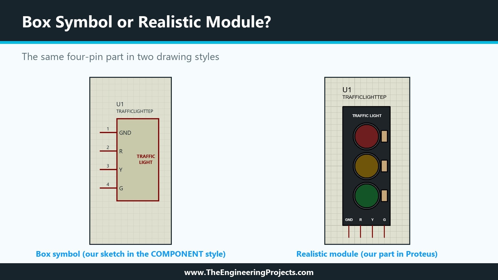
For the Traffic Light Module, the realistic style wins: the whole point of the part is that a student sees the lamps light up as on the real board. We will keep the drawing simple, though: a board, three lamps with rings, three resistors, a title and the pin names. A realistic drawing does not need to be a photograph; it needs the details that make the part recognisable and nothing else.
The picture below puts the two styles side by side. On the left is a box symbol of our module, which we sketched only for this comparison; on the right is the realistic part we build in the coming tutorials, as it looks in Proteus once it is finished.
Step 3: Understand Units, Grid and Snap in Proteus
Before we fix any size, we need the units Proteus uses. The help explains that all coordinates in the schematic editor are held internally in 10 nm units, but the coordinate read-out works in steps of 1 thou, a thousandth of an inch (0.0254 mm). Proteus calls a 1 thou step a unit. The origin of the sheet is in the centre of the work area, so both positive and negative coordinates are used, and the position of the mouse pointer is shown at the bottom right of the window. All sizes in this series are given in thou.
When you move the mouse over the drawing, the coordinates change in fixed steps. This is called snapping: objects land on a neat grid. The snap size is chosen in the View menu, shown below in Proteus 8.5.
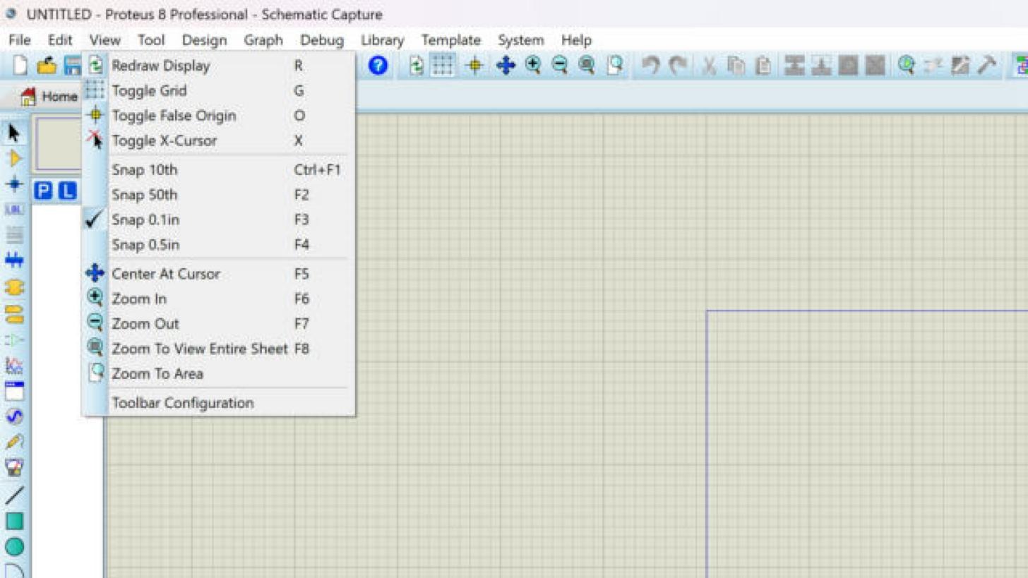
Snap Commands in the View Menu
| Command | Shortcut | What it does |
|---|---|---|
| Snap 10th | Ctrl+F1 | 10 thou steps, for fine graphic details |
| Snap 50th | F2 | 50 thou steps, for most graphics |
| Snap 0.1in | F3 | 100 thou steps, the default, for pins and wiring |
| Snap 0.5in | F4 | 500 thou steps, for rough placement |
| Toggle Grid | G | Switches between line grid, dot grid and no grid |
| Toggle False Origin | O | Sets the coordinate read-out to zero at the mouse position |
| Toggle X-Cursor | X | Shows a cross at the exact snapped position |
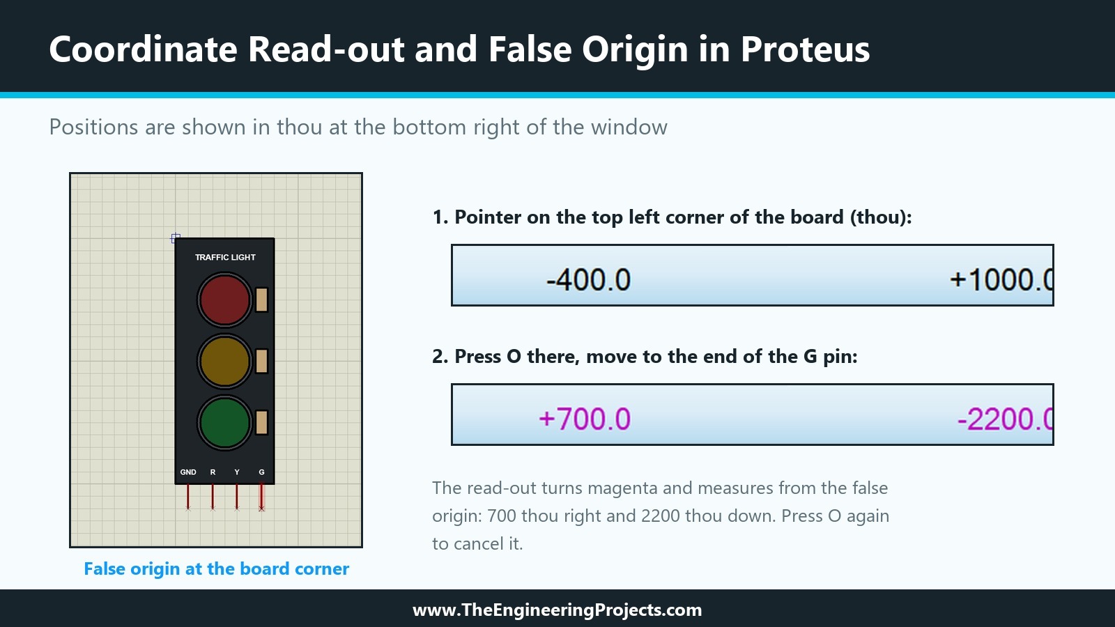
Three details from the help are worth knowing early. First, the grid spacing follows the snap setting, unless that would draw an unreadable number of lines. Second, the false origin is handy for measuring: press O at a corner of your board, and the read-out shows distances from that corner, in magenta as a reminder; press O again to cancel it. Third, when the pointer comes close to a pin end or a wire, Proteus snaps to it even if it is off the grid. This Real Time Snap is a convenience while wiring, but a library part should not rely on it.
Here is what the read-out looks like on the finished module, which we draw in the next tutorial. With the pointer on the top left corner of the board, it shows -400.0 and +1000.0, exactly the corner of our plan. After pressing O at that corner and moving to the end of the G pin, it shows +700.0 and -2200.0 in magenta: the pin end lies 700 thou to the right of the corner and 2200 thou below it.
The Most Important Grid Rule
That leads to the most important grid rule for a library part: put every pin end on the 100 thou grid. People wire with the default Snap 0.1in. If the end of a pin lies off that grid, wires will still connect through Real Time Snap, but they will bend and look untidy, and the part will never sit neatly next to other parts. Graphics have no such restriction; we will draw them with Snap 50th and Snap 10th where needed.
Step 4: Fix the Size and Position of Every Shape
Now we can put numbers on the drawing. We place the origin of our part at the centre of the board, point (0, 0), which makes the drawing symmetrical and the numbers easy to remember. Here is how each size was chosen.
- The board is 800 thou wide and 2000 thou tall, from x = -400 to 400 and from y = -1000 to 1000. The height gives room for three lamps and a title; the width gives room for four pins 200 thou apart with a margin at each side.
- The lamps have a radius of 200 thou, so each one is 400 thou across, about half the board width. Their centres are 500 thou apart, at y = 500, 0 and -500. Each lamp sits in a dark ring with a radius of 230 thou, which leaves a 40 thou gap between neighbouring rings.
- The resistors are small boxes of 100 by 200 thou on the right of each lamp, from x = 250 to 350. They add realism and remind students that the real board has its own resistors.
- The title "TRAFFIC LIGHT" sits at the top, centred at y = 850, and the pin names GND, R, Y and G are printed on the board at y = -900, above their pins.
Why 200 thou between the pins and not 100? Pins 100 thou apart are standard on chips, but here every pin needs a readable name printed above it, and wires coming down from an Arduino need room to bend. With 200 thou, the module is still compact, and it is easy to wire. The part as a whole spans 2200 thou from the top of the board to the ends of the pins, a little more than two inches on the sheet.
The complete plan is collected in the text below. Keep it next to you in the coming tutorials; we will place every object exactly at these coordinates.
TRAFFIC LIGHT MODULE - DESIGN PLAN
Units: thou (1 thou = 0.0254 mm). Origin: centre of the board.
Pin ends on the 100 thou grid (Snap 0.1in); graphics may use Snap 50th or Snap 10th.

DRAWING (bottom layer first)
Board       box      x -400..400, y -1000..1000          black fill, dark outline
Lamp rings  circles  centre x 0, y 500 / 0 / -500, r 230 dark grey
Lamps       circles  centre x 0, y 500 / 0 / -500, r 200 red / amber / green
Resistors   boxes    x 250..350, lamp centre y +/- 100   beige
Title       text     "TRAFFIC LIGHT", centre x 0, y 850  white
Pin names   text     GND R Y G at x -300 / -100 / 100 / 300, y -900

PINS (200 thou long, from the board edge at y -1000 down to y -1200)
No.  Name  Electrical type  Wire end
1    GND   Power            x -300, y -1200
2    R     Input            x -100, y -1200
3    Y     Input            x  100, y -1200
4    G     Input            x  300, y -1200

BEHAVIOUR (as the real module)
Pin HIGH = lamp on, pin LOW = lamp off. Common cathode: all lamps return to GND.

ANIMATION
Three elements (red, yellow, green), each with an off and an on state.
Step 5: Plan the Pins of the Component
Pins deserve the most care, because they are the part's connection to the rest of the world and to its simulation model. For each pin we plan five things: its name, its number, its electrical type, its position and its direction.
| Number | Name | Electrical type | Wire end | Function |
|---|---|---|---|---|
| 1 | GND | Power (PP) | x -300, y -1200 | Common cathode of the three LEDs |
| 2 | R | Input (IP) | x -100, y -1200 | HIGH lights the red lamp |
| 3 | Y | Input (IP) | x 100, y -1200 | HIGH lights the yellow lamp |
| 4 | G | Input (IP) | x 300, y -1200 | HIGH lights the green lamp |
Why These Pin Decisions
A few decisions in this table need a word of explanation.
- Names are taken from the real board, letter for letter. Students read the board label, then look for the same name in Proteus. Short names also fit above the pins.
- Numbers follow the order of the real header from left to right. For a part without a PCB package, the numbers matter less, but they become the pad numbers once we add a footprint later in the series.
- Electrical types follow the table from the previous tutorial: R, Y and G are inputs (IP), because the module only listens to them, and GND is a power pin (PP). The electrical rules check uses these types, and a digital simulation model needs them to be right.
- The GND pin stays visible. Proteus could hide it and connect it to the GND net automatically, but the real module has a GND pin that students must wire, and a visible pin teaches that. Hidden power pins suit chips with many supply pins; they would only confuse a four-pin module.
- Direction: all four pins point down from the bottom edge of the board, like the header of the real module. In Proteus, the blue cross at one end of a pin marks the end where the wire connects; ours will be at y = -1200.
- Length: the DEFAULT pin of Proteus 8.5 is 200 thou long, two grid squares at Snap 0.1in, so our pins run from the board edge at y = -1000 to y = -1200 without any special pin type.
Step 6: Choose the Colours and Graphic Styles
In Proteus, every graphic object follows a graphics style. The COMPONENT style is the default for parts; a graphic that follows it changes when the style is changed, which keeps all box symbols of a schematic looking alike. For a box symbol that is exactly what you want. For a realistic module, it is not: a black board must stay black, and a red lamp must stay red. For those graphics we will switch off "follow global" for the colours and set local values, as the help recommends for fixed parts of a drawing.
| Element | Colour | Why |
|---|---|---|
| Board | Black fill, dark outline | Like most real modules; makes the lamps stand out |
| Lamp rings | Dark grey | Separates each lamp from the board |
| Lamps, off | Dark red, dark amber, dark green | A lamp that is off still shows its colour |
| Lamps, on | Bright red, amber and green | Clear contrast with the off state |
| Resistors | Beige | The usual colour of small resistors |
| Title and pin names | White | Like the silkscreen of a real board |
| Pins | Proteus pin style | Pins should look like pins in every part |
Two Colour Rules
Two colour rules help every realistic part. First, design the off state so that it is clearly a lamp, not an empty hole: dark versions of the lamp colours do that. Second, keep strong contrast between off and on, because many people view schematics zoomed out, where a small change in brightness is invisible.
Step 7: Plan the Layers of the Drawing
A realistic part is built up from overlapping shapes: the lamp sits on its ring, the ring sits on the board. We therefore plan the drawing in groups, from the bottom up, and place them in that order.
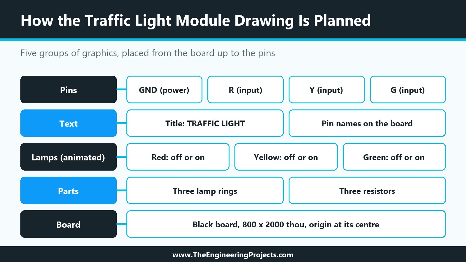
The groups are the board at the bottom, then the parts on it (lamp rings and resistors), then the lamps that will be animated, then the text, and finally the pins. Keeping the lamps as a separate group pays off when we make the animation states, because only that group changes from state to state. In the next tutorials, we will also see how Proteus stacks overlapping filled shapes and how to make reusable symbols out of groups of graphics, for example one lamp with its ring.
Step 8: Plan the Animation States
In the previous tutorial, we met the Active Component settings of the Make Device wizard: a symbol name stem, a number of states, the Bitwise States option and the link to a model DLL. Now we can decide which of them our module needs.
Requirement 3 says the three lamps work independently. With one state per combination, we would need eight drawings: all off, red only, yellow only, green only, red and yellow, and so on. Proteus offers a better fit for parts made of independent on/off elements: bitwise states. Each element gets an off symbol and an on symbol, named after the stem in the form STEM_N_0 and STEM_N_1, where N identifies the element. For three lamps, that is six symbols instead of eight, and adding a fourth lamp would add two symbols, not eight more.
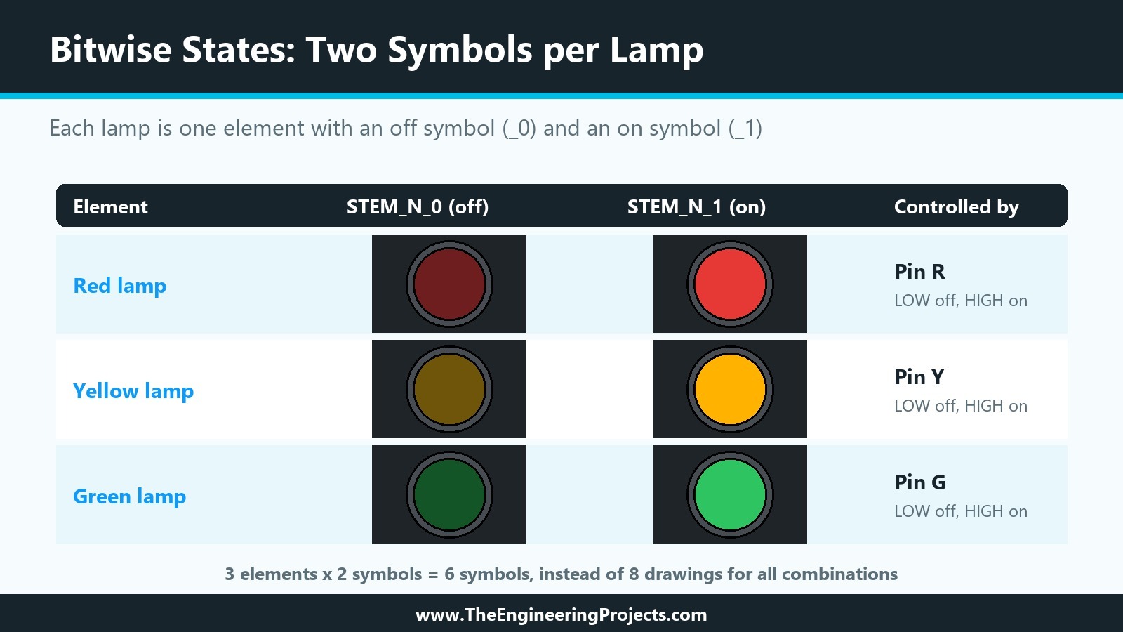
| Element | Controlled by | Symbol ending _0 | Symbol ending _1 |
|---|---|---|---|
| Red lamp | Pin R | Dark red (off) | Bright red (on) |
| Yellow lamp | Pin Y | Dark amber (off) | Bright amber (on) |
| Green lamp | Pin G | Dark green (off) | Bright green (on) |
What switches the states while the simulation runs is the job of the simulation model, which we plan in the second half of the series. For now, it is enough that the drawing is prepared for it: three lamps, each a separate group at a fixed position, each with an off and an on look.
Step 9: Plan the Name, Prefix and Properties
The last decisions concern the data that Make Device stores. We will make them properly in their own tutorials, but it helps to know the direction now.
- Reference prefix: U, like most modules and chips, so the first module on a sheet becomes U1.
- Device name: a short, unique name without spaces, because it also appears in the property script and the model link.
- Index data: a category, sub-category, manufacturer and a description with the words people type into Pick Devices, such as "traffic light", "LED" and "module".
- Properties: the hidden PRIMITIVE and MODDLL that link the model, and perhaps a few user settings later, for example whether the lamps light on HIGH or on LOW.
The Complete Design Checklist
Before drawing any new Proteus component, run through this list. If you can answer every line, the drawing itself will go quickly.
| Question | Traffic Light Module |
|---|---|
| What does the part do? | Shows three lamps that follow the R, Y and G pins |
| Box symbol or realistic? | Realistic, kept simple |
| Where is the origin? | Board centre (0, 0) |
| How big is it? | 800 by 2000 thou board, pins to y = -1200 |
| Are all pin ends on the 100 thou grid? | Yes: x = -300, -100, 100, 300 at y = -1200 |
| Pin names, numbers and types? | GND 1 power; R 2, Y 3, G 4 inputs |
| Hidden pins? | None |
| Fixed colours? | Board, rings, lamps, resistors and text |
| Drawing groups? | Board, parts, lamps, text, pins |
| Animation states? | Three elements, bitwise, off and on |
| PCB package? | Later, optional |
Common Mistakes When Designing a Proteus Component
- Pins off the grid. The part looks fine alone, but every wire to it bends. Check every pin end at Snap 0.1in.
- Pin names that differ from the real part. Students compare the board and the screen; a pin called IN1 in Proteus and R on the board causes wrong wiring.
- Two pins with the same name by accident. Proteus treats them as connected. Use the same name only where the real part really connects them, such as several GND pins.
- Everything in the COMPONENT style. A realistic part whose graphics follow the global style changes its look whenever that style is edited. Fix the colours that must not change.
- A drawing that is too detailed. Tiny details disappear when the schematic is zoomed out and make state drawings slow to create. Draw what helps recognition and leave out the rest.
- No plan for the states. If the animated elements are not separated from the start, the drawing has to be taken apart again later.
In the Next Tutorial
We now have a complete plan for our Traffic Light Module. In the next tutorial, How to Draw a Component Symbol in Proteus with 2D Graphics, we will open Proteus and draw the board, the lamp rings, the lamps, the resistors and the text exactly at the coordinates of our plan, using the line, box, circle, path and text tools.
FAQ
What units does Proteus use for drawing components?
The coordinate read-out of the schematic editor works in thou, thousandths of an inch (1 thou = 0.0254 mm). Internally, Proteus holds coordinates in 10 nm units. The origin is in the centre of the work area.
How do I change the snap grid in Proteus 8?
Use the View menu or the shortcuts: Ctrl+F1 for Snap 10th, F2 for Snap 50th, F3 for Snap 0.1in (the default) and F4 for Snap 0.5in. The G key switches between a line grid, a dot grid and no grid.
Why should the pins of a Proteus component be on a 100 thou grid?
Most people wire at the default Snap 0.1in. Pin ends on that grid give straight, tidy wires and let the part line up with other parts. Pins off the grid still connect through Real Time Snap, but the wires bend.
Should a Proteus component look realistic or be a simple box?
Use a box for chips and professional schematics, where compactness and a consistent style matter. Use a realistic drawing for modules, teaching parts and animated parts, where people should recognise the real board at a glance.
How many states does an animated Proteus component need?
It depends on how its elements work. Parts made of independent on/off elements, like the three lamps of our module, fit the bitwise option: two symbols per element. Parts with one combined state, like a switch with several positions, need one symbol per state.
Can I change the design after the part is made?
Yes: Decompose the part, edit the graphics or pins and run Make Device again. Changes to graphics are easy; changes to pin names and positions affect every design that uses the part, which is why the pins are planned first.
That is all for today. Our Traffic Light Module now exists as a complete plan, and the next tutorial turns it into a real Proteus drawing. If you have any questions, ask in the comments. Take care.
Comments
0