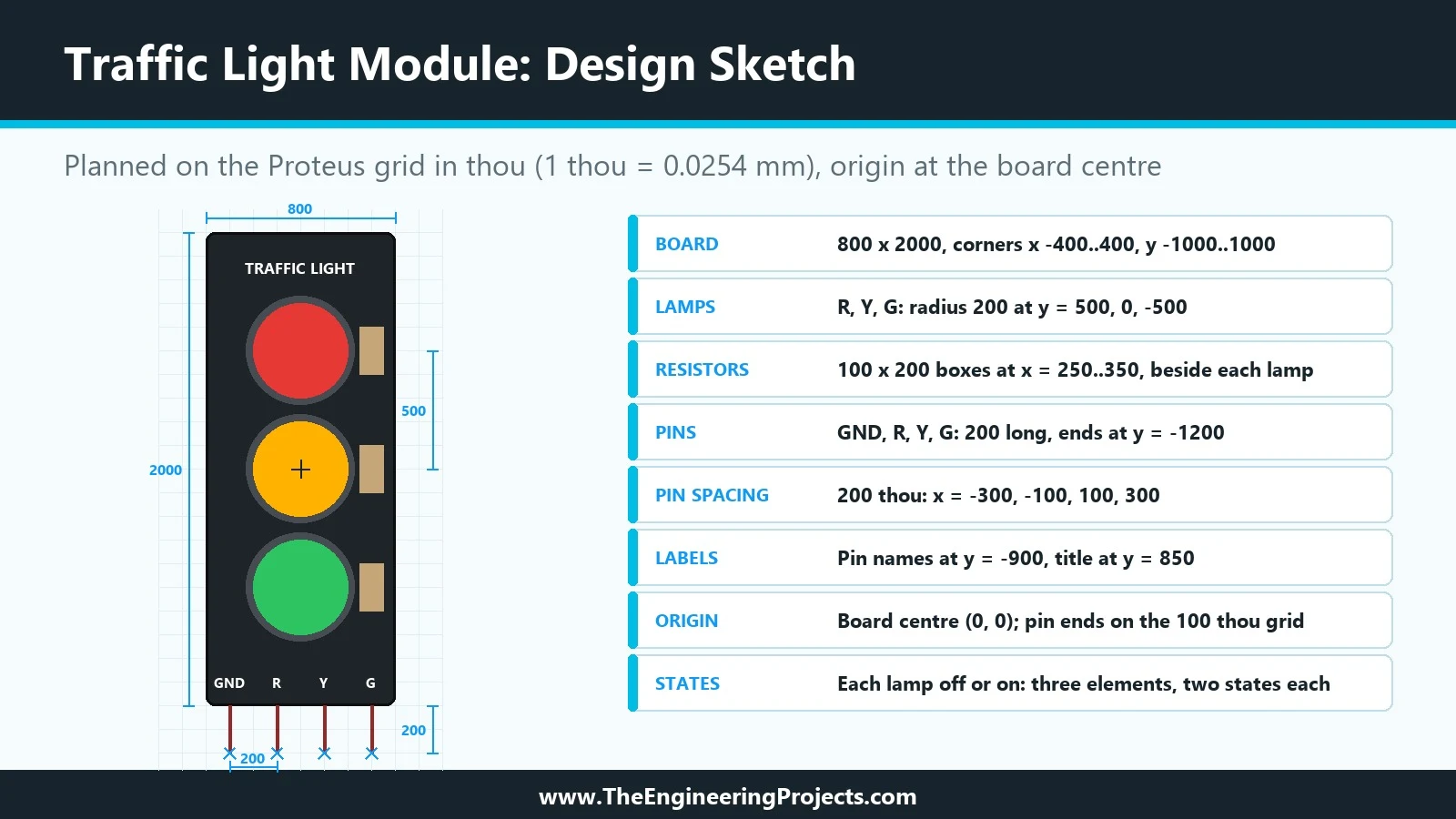
Hello friends, I hope you are doing well. This is the second tutorial in our series on how to create a Proteus library. In the previous tutorial, How to Create a Proteus Library: How It Works Behind the Scenes , we looked at what a library part is made of: the symbol, the pins, the properties, the package, the index and the simulation model, and at what Proteus does with them when you press Run. Today, we start building our own part, and we start the way every good component starts: on paper, before the first line is drawn. Our topic is how to design a new component in Proteus . Updates Proteus Component Designing This course: Part 2 of 20, Designing a Proteus Component Previous part: How a Proteus Library Works Next part: Drawing the Component Symbol Add libraries to Proteus: How to Add a ...
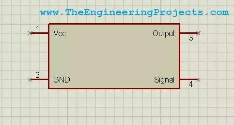
Hello friends! Today we will design a custom component in Proteus ISIS. This is useful when you need to document a circuit but cannot find the exact module, connector, or device in your installed library. We will draw a simple four-pin symbol, define its connections, and save it so that it can be placed like other library parts. The original purpose of this tutorial is schematic presentation, and we will keep that approach. A clear custom symbol helps another person understand how your project is connected. We will also discuss the extra information required before the same part can be used for PCB layout or electrical simulation. Our example is a fictional device named Test Device with VCC, GND, OUTPUT, and SIGNAL connections. These names let us practise the workflow without claiming to r ...