


Proteus Simulation Models Explained


Hello friends, I hope you are doing well. This is the twelfth tutorial in our series on how to create a Proteus library. In the previous tutorial, How to Edit and Update an Existing Component in Proteus, we changed our Traffic Light Module after it was in use and brought the design up to version 1.1. The part is complete as a drawing, with pins, properties and a footprint, but when we press Run, Proteus still stops with "No model specified". Today, we look at what is missing. Our topic is Proteus simulation models explained.
We will see how to tell which model a part uses, go through the four kinds of model that Proteus supports, read the real property scripts of supplied parts that use each kind, find where the model files live, and separate two things that are easy to mix up: the model of a part and its animation. At the end, we compare the ways our own module could be modelled and decide how the series continues.
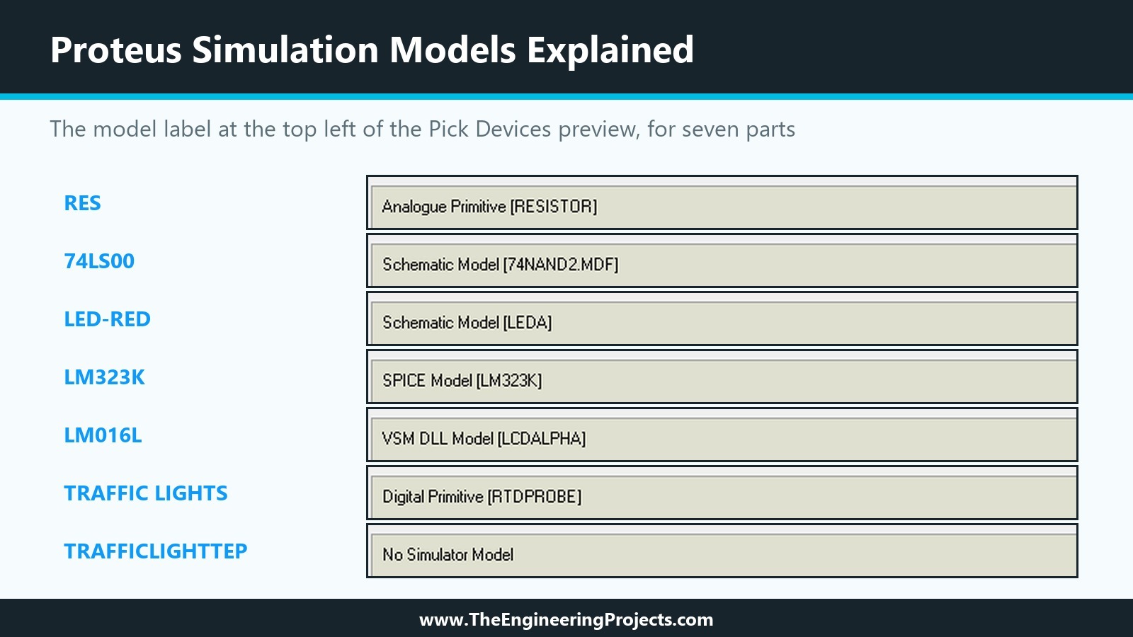
Everything in this tutorial comes from Proteus 8.5 Professional on our PC: the Pick Devices dialogue, the help files and the supplied libraries, which we read without changing them. The picture below shows the quickest way to tell models apart, the label at the top left of the Pick Devices preview, for seven parts.
What Is a Simulation Model in Proteus?
A drawing tells Proteus how a part looks; a simulation model tells it how the part behaves. When you press Run, the simulator, PROSPICE, needs to know for each part what currents flow, which levels its outputs take and how fast it reacts. The model provides exactly that.
Proteus finds a part's model through its properties, the same properties we added in the eighth tutorial. As we saw in the first tutorial, a few property names decide everything: PRIMITIVE, MODFILE, the SPICE properties and MODDLL. The help states that of the more than 8,000 parts supplied, about 6,000 have models; the others are perfectly usable for schematics and boards, and Labcenter calls the idea that every part needs a model untenable.
How to Tell Which Model a Part Uses
The Label in Pick Devices
Pick Devices shows the model type at the top left of the schematic preview. For our seven parts, it read:
- RES, the generic resistor: Analogue Primitive [RESISTOR].
- 74LS00, a quad NAND gate: Schematic Model [74NAND2.MDF].
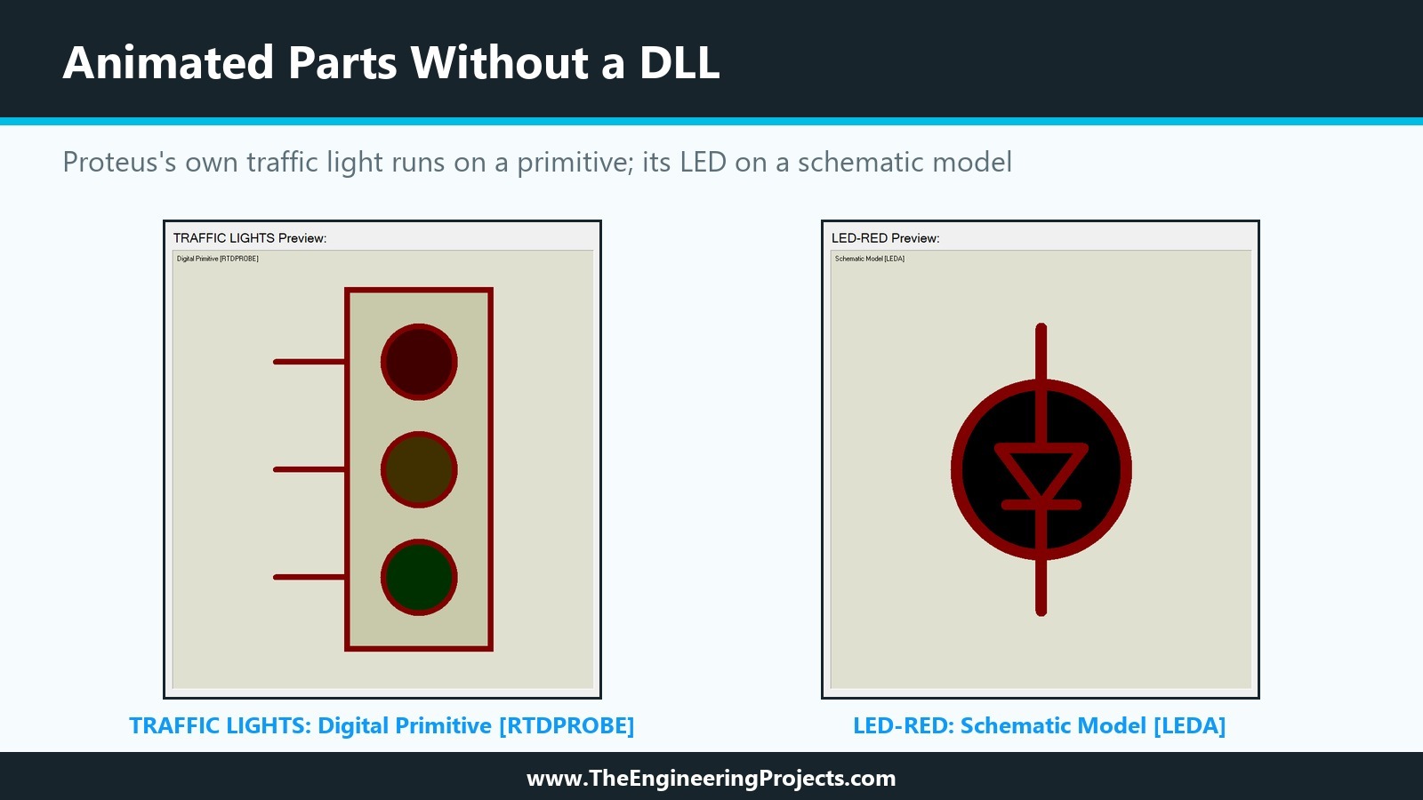
- LED-RED, the animated red LED: Schematic Model [LEDA].
- LM323K, a 5 V regulator: SPICE Model [LM323K].
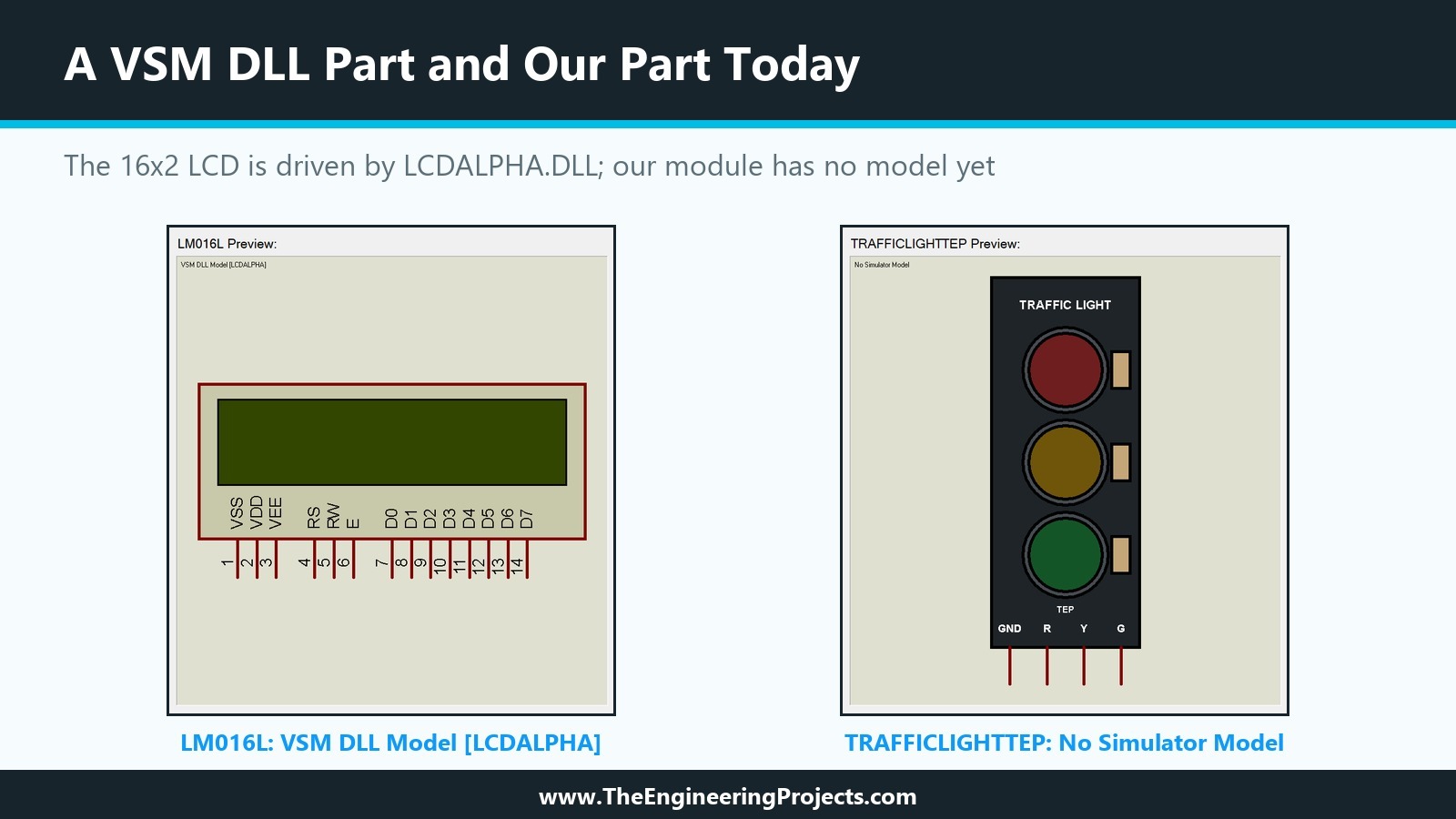
- LM016L, a 16x2 character LCD: VSM DLL Model [LCDALPHA].
- TRAFFIC LIGHTS, Proteus's own traffic light: Digital Primitive [RTDPROBE].
- TRAFFICLIGHTTEP, our part: No Simulator Model.
The help gives 74NAND.MDF as the example for the 74LS00; our Proteus 8.5 shows 74NAND2.MDF. Trust the label in your own installation over any example.
Show Only Parts with Models
Pick Devices also has a tick box, Show only parts with models?, under the Keywords field. With it ticked, a search lists only parts that can be simulated, which saves time when you build a circuit for simulation and do not want to find out at Run time that a part has no model.
The Messages When a Model Is Missing
If a part without a model sits in the simulated circuit, the simulation stops during the partition analysis. As we saw in the first tutorial, Proteus 8.5 reports "No model specified for U1." and "Simulation FAILED due to partition analysis error(s).". The help explains why the check comes this late: until the partition analysis, Proteus does not know whether the unmodelled part is actually in the part of the circuit being simulated. A second message points to a different problem: "Value not found in parameter mapping table" means that a model file exists, but the value of the part, for example 74F00 instead of 74LS00, is not one that the file models.
The Four Kinds of Simulation Model
The help describes four kinds of model. We go through them with real examples, and the property scripts behind each example follow in the next section.
Primitive Models
Primitives are models built into PROSPICE itself. They need no extra file, and a single PRIMITIVE property identifies them, with further properties such as a value passed to the simulator through the netlist. Resistors, capacitors, diodes, transistors, gates, counters, latches and memories are primitives. The standard primitives are in the ASIMMDLS and DSIMMDLS libraries, and the MODELS help file documents the properties of each one.
Analogue and Digital Primitives
The label tells you which side of the simulator a primitive lives on: Analogue Primitive for SPICE-type elements such as the resistor, Digital Primitive for logic elements. The help gives PRIMITIVE=ANALOG,RESISTOR as the resistor's property. The RES part in the Proteus 8.5 library stores it a little differently: PRIMITIVE=ANALOG and a separate PRIMTYPE=RESISTOR, and its PRIMITIVE property is a keyword list with the choices ANALOG and DIGITAL, so the same resistor can be simulated by either side.
Real Time Primitives
A group of digital primitives exists purely to connect the simulation to the screen: the real time probes and switches. One of them, RTDPROBE, the Real Time Digital Probe, matters for us. The help describes it as setting the state of an indicator according to the bitwise value on its input pins, with the pins named D0, D1, D2 and so on. If any input is undefined or floating, it outputs the invalid state. Proteus's own TRAFFIC LIGHTS part is exactly that: a digital primitive of type RTDPROBE.
Schematic Models
For a more complex part, a circuit of primitives that mimics its behaviour is drawn in Proteus and compiled into a model file. The help notes that such a circuit does not have to be the real internals of the part; it usually uses ideal sources and switches to simulate faster. The part points to its model with the MODFILE property, which Labcenter makes read-only by convention. The 74LS00 and the animated LED-RED are schematic models.
Parameter Mapping Tables
One model file can model several parts. A parameter mapping table inside the file maps the value of a part to the parameters of the model, which is how one gate model serves several logic families and how the help's example, the op-amp model OA_BIP, serves the 741 and similar op-amps. When the value of a part is not in the table, you get the parameter mapping message described above.
Where Schematic Models Are Stored
On our installation, the MODELS folder held only nine loose .MDF files. The models we looked for were inside model library files instead: LEDA in ACTIVE.LML, OA_BIP in ANALOG.LML and 74NAND2 in DIGITAL.LML. The label in Pick Devices shows the model name, sometimes with the .MDF extension and sometimes without, but you do not need to know which file holds it.
SPICE Models
PROSPICE is based on Berkeley SPICE3F5, so it accepts standard SPICE models, and many supplied parts use models published by their manufacturers. The help describes two forms: a SUBCKT block, a small circuit in SPICE syntax, and a MODEL record with parameters for a SPICE primitive such as a transistor.
SUBCKT Models
A part with a SUBCKT model carries PRIMITIVE=ANALOG,SUBCKT and names the subcircuit with SPICEMODEL. Our example, the LM323K regulator, also carries SPICEPINS=VI,VO,GND, which tells Proteus the order of the subcircuit's nodes, so that the part's pins connect to the right nodes of the model.
SPICELIB and SPICEFILE
The model text itself lives either in a plain text file named by SPICEFILE, or in a SPICE model library named by SPICELIB. The LM323K uses SPICELIB=ANALOG, and the MODELS folder of our installation contains a file ANALOG.SML, one of 36 .SML files there. The next tutorial adds a SPICE model to a part of our own and goes into these properties in detail.
VSM DLL Models
The help calls VSM models primitives that are implemented in an external DLL instead of inside PROSPICE. Such a part carries both a PRIMITIVE property and a MODDLL property naming the DLL. The LM016L shows it: PRIMITIVE=DIGITAL,LCD and MODDLL=LCDALPHA, and the MODELS folder contains LCDALPHA.DLL with 76,288 bytes. Our own module libraries, such as the HC-12, work the same way; TEPHC12.DLL sits in the same folder.
One DLL, Several Parts
A DLL can implement more than one primitive. The help's example is MCS8051.DLL, which implements several 8051 variants; the part's PRIMITIVE property tells the DLL which one it is. Our LoRa module libraries use the same idea, with one DLL serving several modules.
Animation from a DLL
A VSM model can also drive the graphics of its part, which the help describes as combining the electrical and graphical sides of a component in fairly astounding ways, with the LCD as the example. It is the most powerful kind of model and the only one that can simulate a complete module with its own logic, messages and controls, but it is also the only one that needs programming, in C++ with Labcenter's VSM SDK, which is supplied on request under a non-disclosure agreement.
The Property Scripts Behind Each Model
Here are the relevant lines of five supplied parts, read directly from the library files on our PC. The comment line above each block names the part, its library and the label Pick Devices shows for it.
; RES (DEVICE.LIB), Pick Devices: Analogue Primitive [RESISTOR]
{*COMPONENT}
{VALUE=10k}
{PRIMITIVE=ANALOG}
{PRIMTYPE=RESISTOR}
{PACKAGE=RES40}

; LED-RED (ACTIVE.LIB), Pick Devices: Schematic Model [LEDA]
{*DEVICE}
{PREFIX=D}
{ACTIVE=LED_RED,8}
{*COMPONENT}
{MODFILE=LEDA}
{VF=2.2V}
{IMAX=10mA}

; LM323K (ANALOG.LIB), Pick Devices: SPICE Model [LM323K]
{*COMPONENT}
{PRIMITIVE=ANALOG,SUBCKT}
{SPICEPINS=VI,VO,GND}
{SPICEMODEL=LM323K}
{SPICELIB=ANALOG}
{PACKAGE=TO3}

; 16x2 LCD (DISPLAY.LIB), Pick Devices: VSM DLL Model [LCDALPHA]
{*DEVICE}
{PREFIX=LCD}
{ACTIVE=LCD_16X2,2,DLL}
{*COMPONENT}
{PRIMITIVE=DIGITAL,LCD}
{MODDLL=LCDALPHA}

; TRAFFIC LIGHTS (ACTIVE.LIB), Pick Devices: Digital Primitive [RTDPROBE]
{*DEVICE}
{ACTIVE=TRAFFIC,3,BITWISE}
{*COMPONENT}
{PRIMITIVE=DIGITAL,RTDPROBE}
{PACKAGE=NULL}
Three things stand out:
- The model is chosen by property names alone. PRIMITIVE alone means a built-in primitive, MODFILE a schematic model, SUBCKT with SPICEMODEL a SPICE model, PRIMITIVE with MODDLL a DLL.
- Animation is a separate line. The ACTIVE line in the {*DEVICE} section, which we met in the first tutorial, appears with all three model kinds: LED_RED with 8 states for a schematic model, LCD_16X2 with DLL for a DLL model and TRAFFIC with 3 bitwise states for a primitive.
- Users can choose a model. The resistor's PRIMITIVE and the LED's MODFILE are keyword lists in their definitions, so a user can switch between an analogue and a digital model in the Edit Component dialogue.
Where Proteus Keeps Model Files
As the first tutorial explained, Proteus looks for model files in the folders listed under Simulation Model and Module Folders on the Simulator Settings tab of System Settings. On our installation, that is the Models folder next to the Library folder, and it held 300 files:
| Extension | Files | What they hold |
|---|---|---|
| .DLL | 223 | VSM models, such as LCDALPHA.DLL and our TEPHC12.DLL |
| .SML | 36 | SPICE model libraries, such as ANALOG.SML |
| .LML | 32 | Model libraries with schematic models, such as ACTIVE.LML |
| .MDF | 9 | Loose schematic model files |
Primitives need no file at all. That is why the RTDPROBE-based traffic light simulates without anything in this folder.
Animation and Models: Two Separate Things
It is tempting to think that an animated part needs a DLL. The supplied libraries show otherwise.
Animated Parts Without a DLL
Proteus's own TRAFFIC LIGHTS part uses ACTIVE=TRAFFIC,3,BITWISE: three elements with bitwise states, exactly the arrangement we planned for our lamps in the second tutorial. Its model is the RTDPROBE primitive, which turns the levels on its three inputs into the states of the three lamps. The animated LED-RED uses ACTIVE=LED_RED,8, eight states, with a schematic model. Neither needs any programming.
How the States Are Chosen
In all these parts, the ACTIVE line only tells Proteus how many states the part has and how its state symbols are named; the model decides which state to show while the simulation runs. The RTDPROBE sets it from its inputs, a schematic model through probes inside its circuit, and a DLL from its own code. We will build state symbols of our own in the animation tutorial; for now it is enough to know that the choice of model and the animation are planned separately.
Which Model Does Our Traffic Light Module Need?
Our module has four pins, GND, R, Y and G, three lamps that follow R, Y and G, and a LOGIC property that should decide whether a lamp lights on a high or a low pin. Three of the four kinds of model could drive it.
Option 1: The RTDPROBE Primitive
The simplest route copies Proteus's own traffic light: PRIMITIVE=DIGITAL,RTDPROBE and bitwise states. It needs no file and no code. Its limits fit our module badly, though: the help expects the input pins to be named D0, D1 and D2, while ours must stay R, Y and G to match the real module, and a plain probe has no notion of our LOGIC property.
Option 2: A Schematic Model
A schematic model can wrap such probes in a circuit of our own, with our pin names on the outside; the help mentions that RTDPROBE has an ELEMENT property for exactly this use, when it is part of a schematic model controlling a bitwise indicator. Inside the circuit, logic gates could also invert the inputs for the low-active setting. It needs no programming, only a model compiled from a drawing.
Option 3: A VSM DLL
A DLL can do everything: read the pins by name, honour LOGIC, report messages to the Simulation Log, check the GND connection and draw the lamps. It is how our module libraries work, and it gives the part a behaviour as close to the real module as we like. It is also the most work.
Our Choice for This Series
We will take the path from simple to advanced, as the series promised. The next tutorials cover SPICE models and schematic models with our module in mind, then the animated and interactive part, and later the VSM DLL with its control panel. Each step will be tested in Proteus before we describe it.
| Model | Pin names R, Y, G | LOGIC property | Needs |
|---|---|---|---|
| RTDPROBE primitive | No, expects D0 to D2 | No | Nothing |
| Schematic model | Yes | Possible with logic inside | A drawn and compiled model |
| VSM DLL | Yes | Yes | C++ code and the VSM SDK |
Common Mistakes with Proteus Simulation Models
| Problem | Cause | Solution |
|---|---|---|
| No model specified | The part has no model property | Use a part with a model, add one, or give connectors PRIMITIVE=NULL |
| Value not found in parameter mapping table | The value is not in the model file's table | Choose a modelled value |
| Model DLL not found | The file named in MODDLL is not in a model folder | Copy the DLL into the Models folder and check the name |
| A SPICE part gives node errors | The pin order does not match the subcircuit | Check SPICEPINS against the SUBCKT line |
| An animated part does not change | Its model never sets a new state | Check that the model drives the states the ACTIVE line declares |
In the Next Tutorial
We now know the four kinds of model and what each needs. In the next tutorial, How to Add a SPICE Model in Proteus, we take the first practical step: we attach a SPICE model to a part, set SPICEMODEL, SPICEPINS and the model file, and test it in a simulation.
FAQ
How do I know if a Proteus part has a simulation model?
Select it in Pick Devices and read the label at the top left of the schematic preview, for example Analogue Primitive, Schematic Model, SPICE Model, VSM DLL Model or No Simulator Model. The tick box Show only parts with models? hides the parts without one.
What is a primitive model in Proteus?
A model built into the simulator itself, identified by the PRIMITIVE property, such as a resistor, a gate or the RTDPROBE indicator. It needs no model file.
What is an MDF file in Proteus?
A compiled schematic model: a circuit of primitives drawn in Proteus that mimics a part. Parts point to it with MODFILE; many are stored in model libraries (.LML) in the Models folder.
Where does Proteus keep model DLLs?
In the folders listed as Simulation Model and Module Folders in System Settings, normally the Models folder of the installation.
Do animated Proteus parts always need a DLL?
No. Proteus's own TRAFFIC LIGHTS uses the RTDPROBE primitive and the animated LEDs use schematic models. A DLL is needed for behaviour that the built-in models cannot express.
Can I use manufacturer SPICE models in Proteus?
Yes. PROSPICE is based on SPICE3F5, and SUBCKT and MODEL records can be used through the SPICEMODEL, SPICEFILE or SPICELIB properties, as the next tutorial shows.
That is all for today. We know now what our Traffic Light Module is missing and which ways lead to a working simulation. If you have any questions, ask in the comments. Take care.
Comments
0