


How to Create an Animated Component in Proteus


Hello friends, I hope you are doing well. This is the fifteenth tutorial in our series on how to create a Proteus library. In the previous tutorial, How to Create a Schematic Simulation Model (MDF) in Proteus, we drew the circuit of our Traffic Light Module, compiled it into TRAFFICLIGHT.MDF and let each placed module have its own resistor values. The currents were right, but the three lamps stayed dark whatever we did. Today, we make them light up. Our topic is how to create an animated component in Proteus.
We will see how Proteus animates a part, how it names the pictures of each state, and how a probe inside the model tells the part which picture to show. Then we draw the six lamp states of our module, declare them in Make Device, add a common symbol for the parts of the drawing that never change, put a real time current probe into each lamp branch of the model and test the result with logic switches. On the way, we hit one surprise that the help does not mention, and we show how to avoid it.
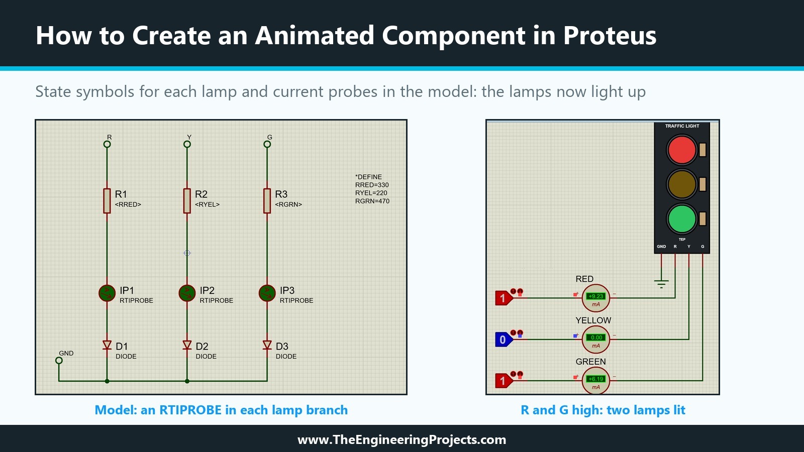
Everything shown here was done in Proteus 8.5 Professional on our PC. The picture below shows the finished result: on the left, the model with a current probe in each branch; on the right, our part during a simulation with the red and green inputs high and the yellow input low.
What Is an Animated Component in Proteus?
An animated component changes its picture while the simulation runs. LEDs light up, switches flip, meters show values and our traffic light will show which lamps are on. Proteus calls such parts active components, and the settings for them sit in the Active Component Properties of the first Make Device page, which we skipped in the seventh tutorial.
The ACTIVE Line in the Device Script
As we saw in the first tutorial, an animated part carries an ACTIVE line in the {*DEVICE} section of its script. Proteus's own traffic light, TRAFFIC LIGHTS in the ACTIVE library, has ACTIVE=TRAFFIC,3,BITWISE, and the animated red LED, LED-RED, has ACTIVE=LED_RED,8. The first value is the symbol name stem, the second the number of states, and the optional BITWISE says how the states are organised.
Normal States and Bitwise States
The help describes the two arrangements on the Device Properties page of Make Device. In the normal case, the number of states is the number of pictures: LED-RED has eight state symbols, LED_RED_0 to LED_RED_7, one for each brightness level. With Bitwise States ticked, the part consists of several independent elements, each with an off and an on picture, so the number of symbols is twice the number of states. Proteus's traffic light has three elements, three lamps, and six state symbols, TRAFFIC_0_0 to TRAFFIC_2_1.
Our module needs exactly that. In the second tutorial, we planned three elements with bitwise states, because a buggy sketch may switch on two lamps at once and the simulation should show it, instead of being limited to "red", "yellow" or "green".
Who Decides Which State Is Shown?
The ACTIVE line only tells Proteus how many states the part has and how the symbols are named. Something in the simulation must set the state. In the twelfth tutorial, we saw that this is the model's job: Proteus's traffic light uses the RTDPROBE primitive as its whole model. Inside a schematic model, the real time probes do the same job. The MODELS help describes three of them:
- RTDPROBE, the real time digital probe, sets the state from the logic levels on its inputs.
- RTVPROBE, the real time voltage probe, sets it from a voltage between a MIN and a MAX value.
- RTIPROBE, the real time current probe, sets it from a current between MIN and MAX.
All three have an ELEMENT property, which the help explains is used when the probe is part of a schematic model controlling a bitwise indicator. Labcenter's LEDA model, which drives LED-RED, uses an RTIPROBE with MAX=<IMAX>. For our module, a current probe is the natural choice too: a real LED lights because current flows through it, not because a voltage is present.
How Proteus Names the State Symbols
The pictures of an animated part are ordinary symbols, made with Make Symbol as in the fifth tutorial. Their names are what links them to the part.
STEM_N_0 and STEM_N_1
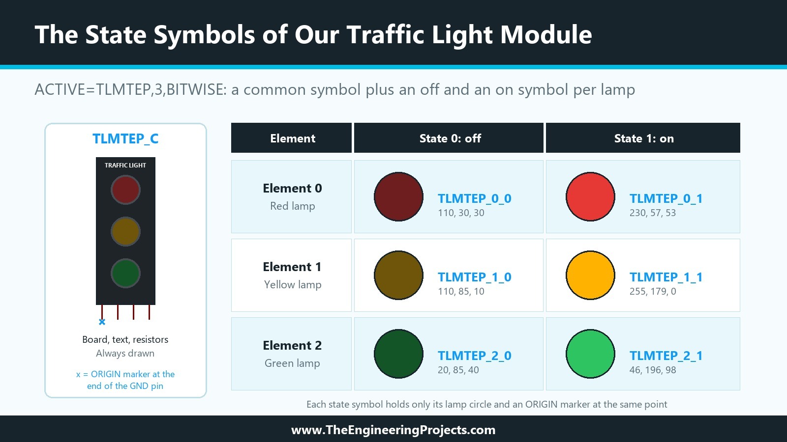
The help gives the naming rule: a bitwise active component has symbols named STEM_N_0 and STEM_N_1 for each element N. We chose the stem TLMTEP, short for Traffic Light Module TEP, and numbered the elements from the top of the module: element 0 is the red lamp, element 1 the yellow lamp and element 2 the green lamp. That gives six symbols:
| Element | Lamp | Off symbol and colour | On symbol and colour |
|---|---|---|---|
| 0 | Red | TLMTEP_0_0, 110, 30, 30 | TLMTEP_0_1, 230, 57, 53 |
| 1 | Yellow | TLMTEP_1_0, 110, 85, 10 | TLMTEP_1_1, 255, 179, 0 |
| 2 | Green | TLMTEP_2_0, 20, 85, 40 | TLMTEP_2_1, 46, 196, 98 |
The off colours are the ones our lamps already have, and the on colours are the ones we planned in the colour table of the fourth tutorial, written down there for exactly this moment.
The Common Symbol STEM_C
The help does not mention it, but Labcenter's animated parts have one more symbol. Next to TRAFFIC_0_0 to TRAFFIC_2_1, ACTIVE.LIB contains TRAFFIC_C, and the same pattern appears for many other animated parts in that library, such as SINE_C, ROTOR_C, SPEAKER_C, DIPSW_C and RELAY_C. We found out what it is for the hard way, as you will see in Step 5: once the model sets the states, Proteus draws the state symbols and the common symbol, not the part's own drawing. Everything that does not change, the board, the rings, the resistors and the text, belongs in the common symbol.
An Origin Marker in Every Symbol
Each state symbol is drawn on top of the part at a fixed position, so every symbol needs an Origin marker at the same point as the part's own origin. In the seventh tutorial, we noted that Proteus used the end of the GND pin as the origin of our device, and a decomposed copy shows the Origin marker exactly there. Our red lamp's centre lies 300 thou to the right of that point and 1,700 thou above it, so the Origin marker of each red lamp symbol goes 300 thou to the left of the lamp centre and 1,700 thou below it. If the marker is off by one grid step, the lamp is drawn one grid step away from the board.
How to Create an Animated Component in Proteus: Step by Step
Making our part animated took seven steps: four for the pictures, one for the Make Device settings, one for the model and one to store and run the result.
Step 1: Copy One Lamp and Add an Origin Marker
In our test project, we tagged the red lamp circle of the drawing next to U1 and used Block Copy to put one copy into an empty part of the sheet, away from everything else. Its Edit Circle tab showed X = -1.9 in, Y = 1 in and a radius of 0.2 in, so the virtual board centre of this copy is 500 thou below the lamp.
Then we chose the Markers mode, picked ORIGIN from the list and placed it 300 thou to the left of the lamp centre and 1,700 thou below it, checking the position with the coordinate read-out before the click. The Markers list in Proteus 8.5 offers ORIGIN, NODE, BUSNODE, LABEL, PINNAME, PINNUM, INCREMENT, DECREMENT and TOGGLE.
Step 2: Store the Off State with Make Symbol
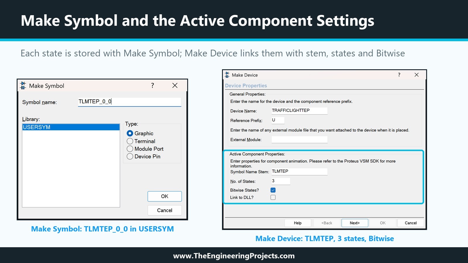
With a tag box around the lamp and the marker, we chose Library, Make Symbol, typed TLMTEP_0_0, kept the type Graphic and stored it in USERSYM, the only library Make Symbol offered. Make Symbol keeps the tagged shapes on the sheet as they are, so the same circle can be reused for the next state.
Step 3: Colour the Lamp and Store the On State
For the on state, we opened the circle's Edit Style tab, chose other... for the fill colour and typed 230, 57, 53, the bright red of our colour plan. The lamp now looked lit. A new tag box around the lamp and the marker, Make Symbol again, and TLMTEP_0_1 was stored.
Moving the Circle Instead of Drawing It Again
For the yellow and green lamps, we did not draw new circles. In the Edit Circle tab, we changed Y from 1 in to 0.5 in, which moved the circle 500 thou down, exactly to where the yellow lamp sits relative to the Origin marker, and set the off colour 110, 85, 10. Make Symbol stored TLMTEP_1_0, the on colour 255, 179, 0 gave TLMTEP_1_1, and with Y = 0 in and the green colours we stored TLMTEP_2_0 and TLMTEP_2_1. Six symbols took a few minutes this way, and all six share exactly the same Origin marker.
A Pitfall: Toolbar Clicks While a Symbol Tool Is Armed
After Make Symbol, the new symbol is selected in the 2D graphics symbol mode. Our next clicks on the mode toolbar landed on the sheet as symbol placements: three stray copies of TLMTEP_0_0 appeared at the top edge of the sheet, which we only noticed with Zoom To View Entire Sheet. End the symbol mode with a right-click on an empty part of the sheet before you click anything else, and look at the whole sheet afterwards.
Step 4: Declare the States in Make Device
We opened Make Device on U1. On the first page, Device Properties, the Active Component Properties need three entries:
- Symbol Name Stem: TLMTEP.
- No. of States: 3, one per element. The field is greyed out until the stem is filled in.
- Bitwise States? ticked. The box becomes active only once the number of states is set.
Link to DLL? stays unticked; it is for VSM DLL models, which come later in the series. On the Component Properties page, we raised VERSION from 1.3 to 1.4, and on the last page we stored the part in TEPTUTORIAL as before.
Step 5: Add the Common Symbol TLMTEP_C
Before adding the probes, we pressed Run once. The part looked exactly as before, complete board and dark lamps, because nothing in the model set a state yet. Then we added the probes, which we describe in the next step, and ran the simulation again.
What Went Wrong Without It
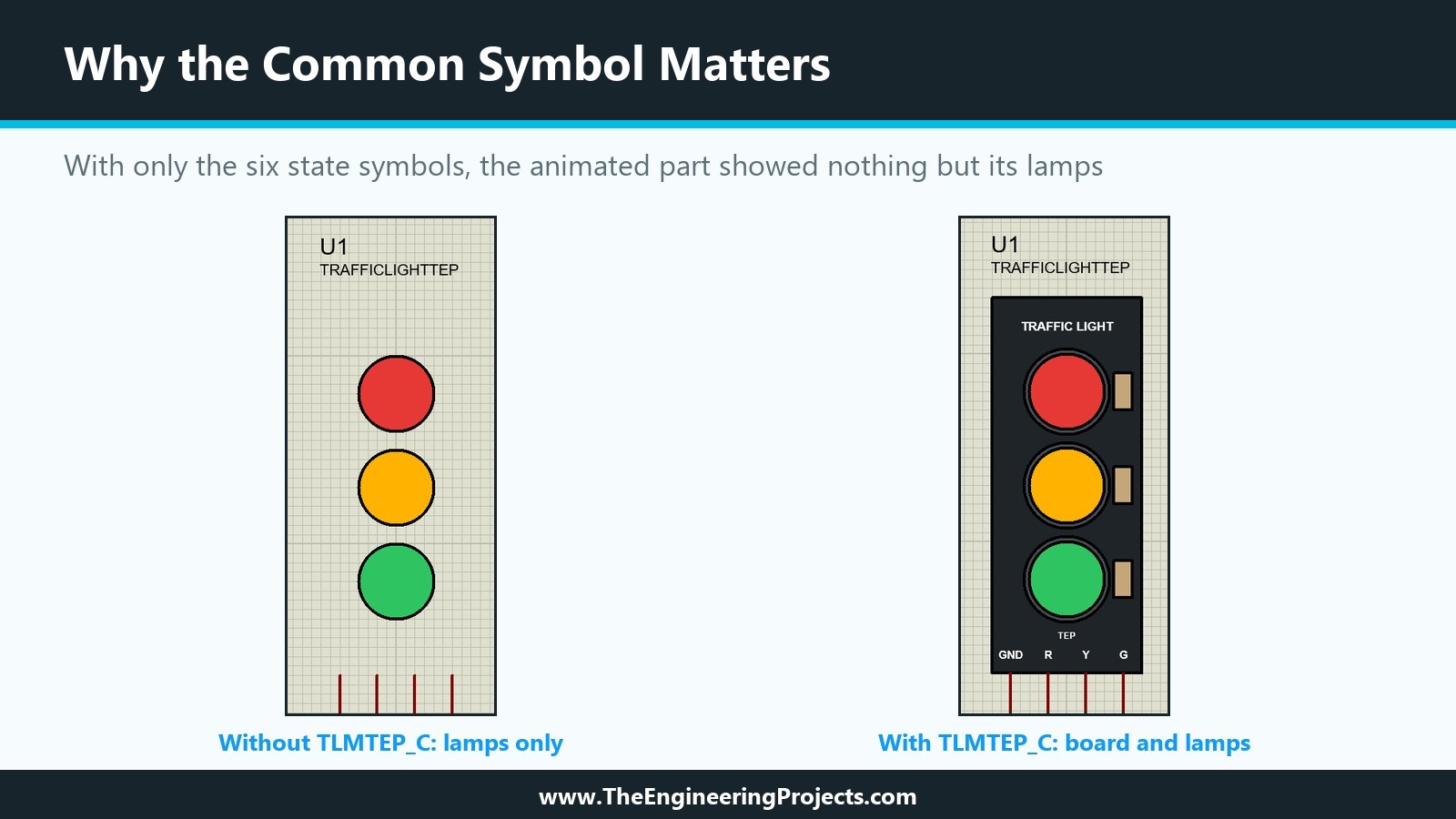
The lamps lit up, but the board, the rings, the resistors, the title and the pin names had disappeared. Only the three coloured circles and the four pins were left on the sheet. As soon as the model set the states, Proteus drew the part from its state symbols alone, and our symbols contained nothing but the lamps.
Making the Common Symbol
We placed a second copy of our part, decomposed it, deleted its four pins and its text script, and kept the graphics and the Origin marker at the end of the GND pin. A tag box around them and Make Symbol with the name TLMTEP_C stored the common symbol. The dark lamps of the original drawing can stay in it, because the state symbols are drawn on top of them. Then we ran Make Device on U1 once more, without changing anything, so that the part picked up the new symbol, and deleted the leftover graphics from the sheet. The next run showed the complete board with lit lamps.
Step 6: Add Real Time Current Probes to the Model
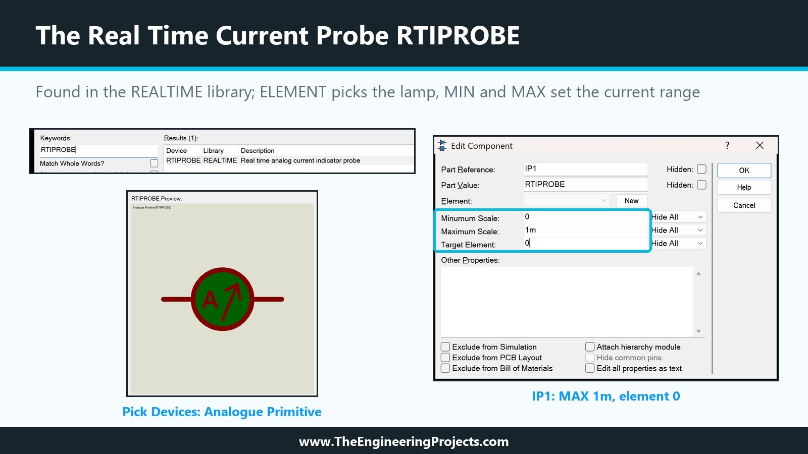
The probes belong in the model, so we opened the model project TRAFFICLIGHT from the previous tutorial. RTIPROBE is in the REALTIME library, which Pick Devices lists as Analogue Primitive [RTIPROBE] with the description Real time analog current indicator probe.
We deleted the wire between each resistor and its diode, moved the diodes and the GND line down with a tag box and Block Move to make room, placed three RTIPROBEs rotated by 90 degrees and wired each one between its resistor and its diode. The probe's plus terminal goes towards the resistor, so the LED current flows into it.
The Probe Properties: ELEMENT, MIN and MAX
In the Edit Component dialogue, an RTIPROBE shows Minimum Scale, Maximum Scale and Target Element, which are MIN, MAX and ELEMENT in the model file. We set Target Element to 0 for IP1 in the red branch, 1 for IP2 and 2 for IP3, and Maximum Scale to 1m, one milliamp, for all three, keeping Minimum Scale at 0. The help gives the rule: the probe outputs a state between 0 and the number of states minus one, scaled between MIN and MAX and rounded to the nearest integer. A bitwise element has two states, off and on, so the lamp switches on when the current reaches half of MAX, 0.5 mA in our case.
The Compiled Model
After saving the project, Tool, Model Compiler wrote the new TRAFFICLIGHT.MDF, now 1,102 bytes:
LISA MODEL DESCRIPTION FORMAT 8.0
=================================
Design:   TRAFFICLIGHT.pdsprj
Doc. no.: <NONE>
Revision: <NONE>
Author:   <NONE>
Created:  10/1/2026
Modified: 10/1/2026

*PROPERTIES,3
RGRN=470
RRED=330
RYEL=220

*MODELDEFS,0

*PARTLIST,9
D1,DIODE,DIODE,IS=4E-13,N=3,PRIMITIVE=ANALOGUE,RS=10
D2,DIODE,DIODE,IS=1E-13,N=3,PRIMITIVE=ANALOGUE,RS=10
D3,DIODE,DIODE,IS=3E-14,N=3,PRIMITIVE=ANALOGUE,RS=10
IP1,RTIPROBE,RTIPROBE,ELEMENT=0,MAX=1m,MIN=0,PRIMITIVE=ANALOG
IP2,RTIPROBE,RTIPROBE,ELEMENT=1,MAX=1m,MIN=0,PRIMITIVE=ANALOG
IP3,RTIPROBE,RTIPROBE,ELEMENT=2,MAX=1m,MIN=0,PRIMITIVE=ANALOG
R1,RES,<RRED>,PRIMITIVE=ANALOG,PRIMTYPE=RESISTOR
R2,RES,<RYEL>,PRIMITIVE=ANALOG,PRIMTYPE=RESISTOR
R3,RES,<RGRN>,PRIMITIVE=ANALOG,PRIMTYPE=RESISTOR

*NETLIST,10
#00001,2
R1,PS,2
IP1,PS,+

#00003,2
R2,PS,2
IP2,PS,+

#00005,2
R3,PS,2
IP3,PS,+

#00007,2
D1,PS,A
IP1,PS,-

#00008,2
D2,PS,A
IP2,PS,-

#00009,2
D3,PS,A
IP3,PS,-

R,2
R,GT
R1,PS,1

Y,2
Y,GT
R2,PS,1

G,2
G,GT
R3,PS,1

GND,4
GND,GT
D1,PS,K
D3,PS,K
D2,PS,K
The part list shows the three probes with their ELEMENT, MIN and MAX values. In the netlist, each resistor's pin 2 now meets the plus terminal of its probe, and the minus terminal meets the anode of the diode. The outside connections R, Y, G and GND are unchanged, so our part did not need any change for the new model; MODFILE=TRAFFICLIGHT simply loads the new file at the next run.
Step 7: Store the Part and Run
Here is the device part of the script as Make Device stored it in TEPTUTORIAL.LIB, read directly from the library file:
; TRAFFICLIGHTTEP version 1.4, read from TEPTUTORIAL.LIB after Make Device
{*DEVICE}
{PREFIX=U}
{ACTIVE=TLMTEP,3,BITWISE}
{*PROPDEFS}
{LOGIC="Lamps light when the pin is",HILOW}
{VERSION="Library version",READONLY STRING}
{PACKAGE="PCB Package",PACKAGE,1,TRAFFICLIGHT-TEP}
{MODFILE="LISA Model File",READONLY STRING}
{RRED="Red lamp resistor",STRING}
{RYEL="Yellow lamp resistor",STRING}
{RGRN="Green lamp resistor",STRING}
{*COMPONENT}
{LOGIC=1}
{VERSION=1.4}
{PACKAGE=TRAFFICLIGHT-TEP}
{MODFILE=TRAFFICLIGHT}
{RRED=330}
{RYEL=220}
{RGRN=470}

; Symbols stored next to the device: TLMTEP_C, TLMTEP_0_0, TLMTEP_0_1,
; TLMTEP_1_0, TLMTEP_1_1, TLMTEP_2_0, TLMTEP_2_1
The ACTIVE line is the only change in the script itself. The seven symbols, however, were copied into TEPTUTORIAL.LIB next to the device; the library grew to 50,578 bytes. That matters for sharing: a user of our library does not need our USERSYM.LIB to see the animation. With the +3.3V terminals from the previous tutorials still connected, the run showed all three lamps lit and the familiar currents of 4.43, 5.98 and 2.79 mA.
How to Test the Animated Part
All lamps on is a good first sign, but a traffic light is about switching lamps individually, so we replaced the three +3.3V terminals with LOGICSTATE parts from the ACTIVE library, one for each of R, Y and G. A LOGICSTATE is a latched logic source: each click on it during the simulation toggles it between 0 and 1.
One Lamp at a Time
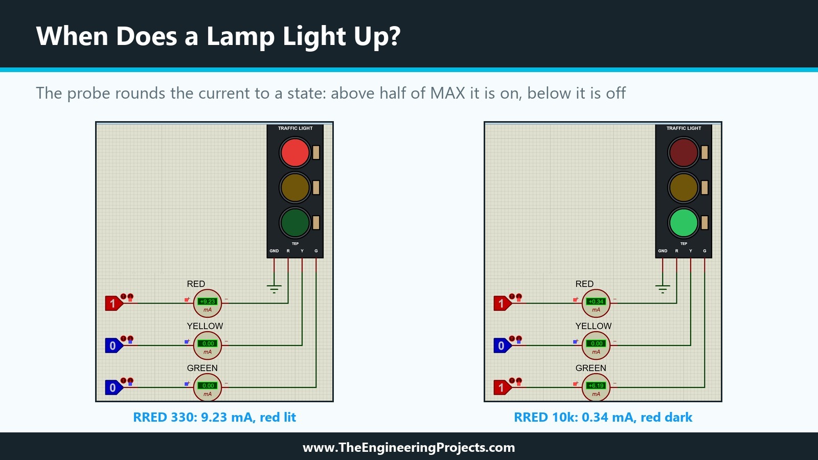
We pressed Run with all three at 0: all lamps dark and all ammeters at 0.00 mA. A click on the red LOGICSTATE turned it to 1, and the red lamp lit with 9.23 mA. This is a little less than the 9.26 mA we measured from a +5V terminal in the thirteenth tutorial. The LOGICSTATE is a digital part, and Proteus converts its high level into an analogue voltage for our model through its mixed-mode interface, which need not behave like an ideal 5 V source.
Two Lamps at Once
Then we also clicked the green LOGICSTATE. Red and green lit together, with 9.23 and 6.19 mA, while yellow stayed dark: exactly the buggy sketch case from our design plan, which a part limited to one state at a time could not show. You can see this state on the right of the first picture.
When Does a Lamp Light Up?
Finally, we tested the threshold. With the red resistor of U1 set to 10k, the red current was only 0.34 mA, and the red lamp stayed dark although current flowed, because 0.34 mA is below half of the probe's 1 mA maximum. Back at 330 ohm, it lit again. A real LED glows faintly at 0.34 mA, so our choice of MAX sets where the simulated lamp counts as on; with Maximum Scale at 0.5m, the threshold would be 0.25 mA. For a teaching part, a clear on and off at a sensible current is more useful than an exact glow, and 1 mA is far below any current a sensible sketch drives through the module.
After the tests, we set the red resistor back to 330 and saved both projects.
What About the LOGIC Property?
Our part still has the LOGIC property from the eighth tutorial, and it still does nothing. Our model describes the common module where each lamp lights when its pin is high, with the LEDs returning to GND. A module that lights on a low pin has its LEDs connected to the supply instead, which is a different circuit with a supply pin our module does not have. Rather than hide this behind a property, we leave LOGIC unused for now and come back to it with the VSM DLL model later in the series, where code can honour it.
Common Mistakes When Creating an Animated Component in Proteus
| Problem | Cause | Solution |
|---|---|---|
| The board disappears when the part is animated | No common symbol | Make STEM_C from the unchanging graphics |
| The lamps are drawn beside the board | The Origin marker of a state symbol is not at the part's origin | Place the marker at the same point relative to the drawing in every symbol |
| The lamps never change | Nothing in the model sets the state | Add a real time probe with the right ELEMENT |
| The wrong lamp lights | ELEMENT does not match the symbol numbers | Element N must drive STEM_N_0 and STEM_N_1 |
| A lamp stays dark although current flows | The current is below half of MAX | Lower MAX, or check the resistor value |
| Bitwise States cannot be ticked | The stem or the number of states is empty | Fill in the stem first, then the states |
| Stray symbols appear at the sheet edge | Toolbar clicks while a symbol tool was armed | Right-click on empty sheet first, then check the whole sheet |
In the Next Tutorial
Our Traffic Light Module now shows its lamps during the simulation, and each lamp follows its own pin. In the next tutorial, How to Design a User Interactive Library in Proteus, we turn to parts that react to the mouse while the simulation runs, using the INCREMENT, DECREMENT and TOGGLE markers we met in the Markers list today.
FAQ
How do I make an animated component in Proteus?
Draw one symbol per state, named after a stem, store them with Make Symbol, and enter the stem and the number of states in the Active Component Properties of Make Device. Then make sure the part's model sets the state, for example with a real time probe in a schematic model.
What does Bitwise States mean in Proteus?
The part has several independent elements, each with an off and an on symbol named STEM_N_0 and STEM_N_1. Our traffic light has three elements, so it needs six state symbols.
Why did my animated part lose its body?
Once the model sets the states, an animated part is drawn from its symbols. Put everything that never changes into a common symbol named STEM_C, as Labcenter does with TRAFFIC_C.
What is RTIPROBE in Proteus?
The real time current probe from the REALTIME library. Inside a schematic model, it sets the state of an animated part from the current through it, scaled between its MIN and MAX properties; ELEMENT selects the element of a bitwise part.
Do I need a DLL to animate a Proteus part?
No. Our part, Proteus's traffic light and the animated LEDs are all animated without a DLL. A DLL is needed only when the behaviour cannot be built from the supplied primitives.
That is all for today. Our Traffic Light Module finally lights up, one lamp or several at a time, just like the real board. If you have any questions, ask in the comments. Take care.
Comments
0