


How to Draw a Component Symbol in Proteus with 2D Graphics


Hello friends, I hope you are doing well. This is the third tutorial in our series on how to create a Proteus library. In the previous tutorial, How to Design a New Component in Proteus, we planned our Traffic Light Module on paper: an 800 by 2000 thou black board, three lamps in rings, three resistors, a title, four pin names and four pins, every shape with its exact coordinates. Today, we open Proteus and turn that plan into a real drawing. Our topic is how to draw a component symbol in Proteus with 2D graphics.
We will look at the 2D graphics tools of the schematic editor, see how to place a box, a circle and text, how to type exact sizes and positions into the Edit Properties dialogue, how to copy shapes precisely with Block Copy and how Proteus stacks overlapping shapes. Step by step, we will draw the board, the lamp rings, the lamps, the resistors, the title and the pin names of our module. The colours are set along the way; the next tutorial explains the colour and style settings in depth.
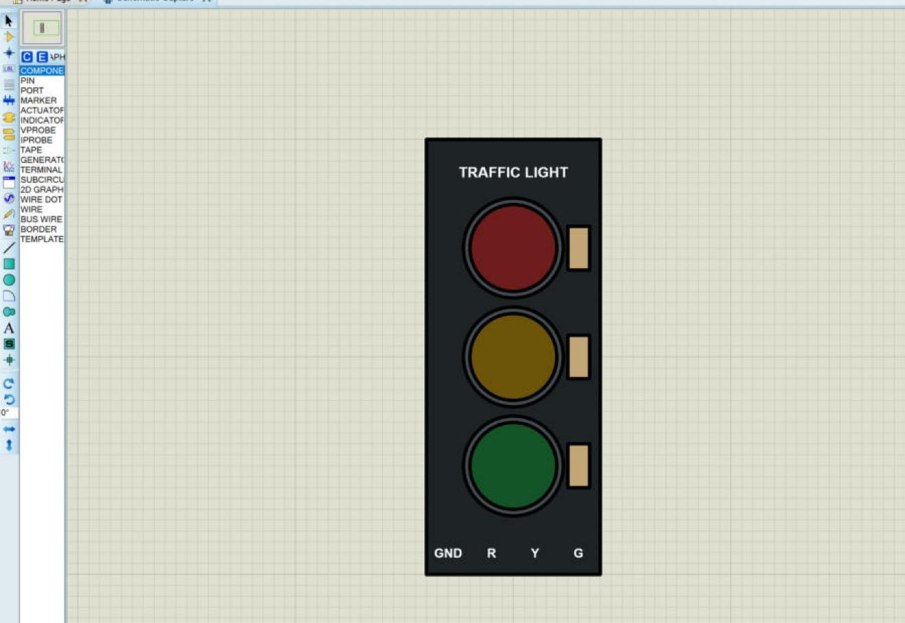
Everything in this tutorial was done in Proteus 8.5 Professional on our own PC, and every screenshot shows our real drawing. The values in the dialogues are the ones we typed, so you can reproduce the module exactly. The picture below shows the finished drawing in the schematic editor, with the 2D graphics tools in the toolbar on the left.
What Are 2D Graphics in Proteus?
The Proteus help describes 2D graphics as lines, boxes, circles, arcs, scalable text and composite symbols. You can use them directly on a schematic, for example to draw a frame around part of a circuit, and they are also the building blocks of new library parts: devices, symbols, pins and terminals. Everything you see in the body of a component, from a simple rectangle to a realistic module, is made of these few objects.
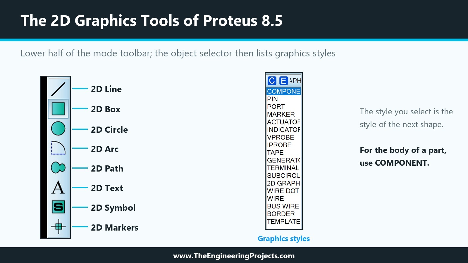
The 2D graphics tools sit in the lower half of the mode toolbar on the left side of the schematic editor. In Proteus 8.5, they are, from top to bottom:
| Tool | What it draws | How you place it |
|---|---|---|
| 2D Line | A straight line | Click the start point, then the end point |
| 2D Box | A rectangle, filled or empty | Click one corner, then the opposite corner |
| 2D Circle | A circle, filled or empty | Click the centre, then a point on the circle |
| 2D Arc | A quarter of an ellipse, shaped with handles | Mark the two ends of the quadrant |
| 2D Path | A closed outline of straight and curved segments | Click the vertices; hold Ctrl for curves; end on the first vertex |
| 2D Text | Scalable text | Click the anchor point, then type into the dialogue |
| 2D Symbol | A saved group of graphics from a symbol library | Pick it from the symbol library and place it |
| 2D Markers | Special points such as the origin of a part | Pick the marker type and place it |
When you select one of these tools, the object selector next to the toolbar no longer lists components; it lists graphics styles instead: COMPONENT, PIN, PORT, MARKER, ACTUATOR, INDICATOR, VPROBE, IPROBE, TAPE, GENERATOR, TERMINAL, SUBCIRCUIT, 2D GRAPHIC, WIRE DOT, WIRE, BUS WIRE, BORDER and TEMPLATE. The style you select is the style of the next object you draw. For the body of a component, the help recommends the COMPONENT style, and that is what we use for every shape of our module. If you still work with the older Proteus 7 ISIS, our earlier post Component Designing in Proteus ISIS covers the basics there; this series follows Proteus 8.5.
Before You Start: Grid, Snap and the Coordinate Display
As we saw in the previous tutorial, the coordinate display at the bottom right of the window shows the position of the mouse in thou, with the origin in the middle of the sheet. We draw the module around that origin, so the numbers of our plan can be used directly. Keep an eye on the display while you draw: it is the easiest way to check that a corner or a centre lands where it should.
Two snap settings are enough for this drawing. Snap 0.1in (F3), the default, puts every point on a 100 thou grid; we use it for the board and the circles, whose positions are multiples of 100. Snap 50th (F2) halves the grid; we need it for the resistors and the title, which sit on multiples of 50. Anything finer, like the 230 thou radius of the rings, we simply type into the Edit Properties dialogue.
While a box or circle is being drawn, the status bar at the bottom of the window shows its values. For a box it reads "Box: P1" and "P2" with the coordinates of the two corners and the width; for a circle it reads "Cen/P1" with the centre and "Rad" with the radius. Watching this read-out is the fastest way to draw accurately with the mouse.
How to Draw the Component Step by Step
We draw the module in six steps, from the board at the bottom to the labels on top. Two techniques we need along the way, exact sizes and exact copies, get their own sections.
Step 1: Draw the Board with the Box Tool
The board is a simple box from x = -400 to 400 and from y = -1000 to 1000 thou.
- Select the 2D Box tool and make sure COMPONENT is selected in the style list.
- Set Snap 0.1in with F3.
- Move the mouse until the coordinate display shows -400, +1000 and click: this is the top left corner.
- Move the mouse down and to the right until the display shows +400, -1000 and click again: the box is placed.
A new box takes the colours of the COMPONENT style, a dark red outline with a light fill. We will make it black later; first, let us see how to check and correct its size. Drawing corner to corner on the grid is the quickest way to place a box exactly. When we drew our board, we first drew a box of any size and typed the numbers into the dialogue instead, and that taught us the lesson in the next section.
How to Set an Exact Size and Position in Proteus
Every 2D graphic has an Edit Properties dialogue in which its position and size can be typed. To open it, choose the selection mode (the arrow at the top of the toolbar) and right-click the outline of the object. For filled shapes, the outline matters: a right-click in the middle of a circle or box opens the menu of the sheet, not the menu of the shape. The context menu of a 2D graphic offers Drag Object, Edit Properties (Ctrl+E), Delete Object, the rotate and mirror commands, Cut and Copy To Clipboard, and Decompose.
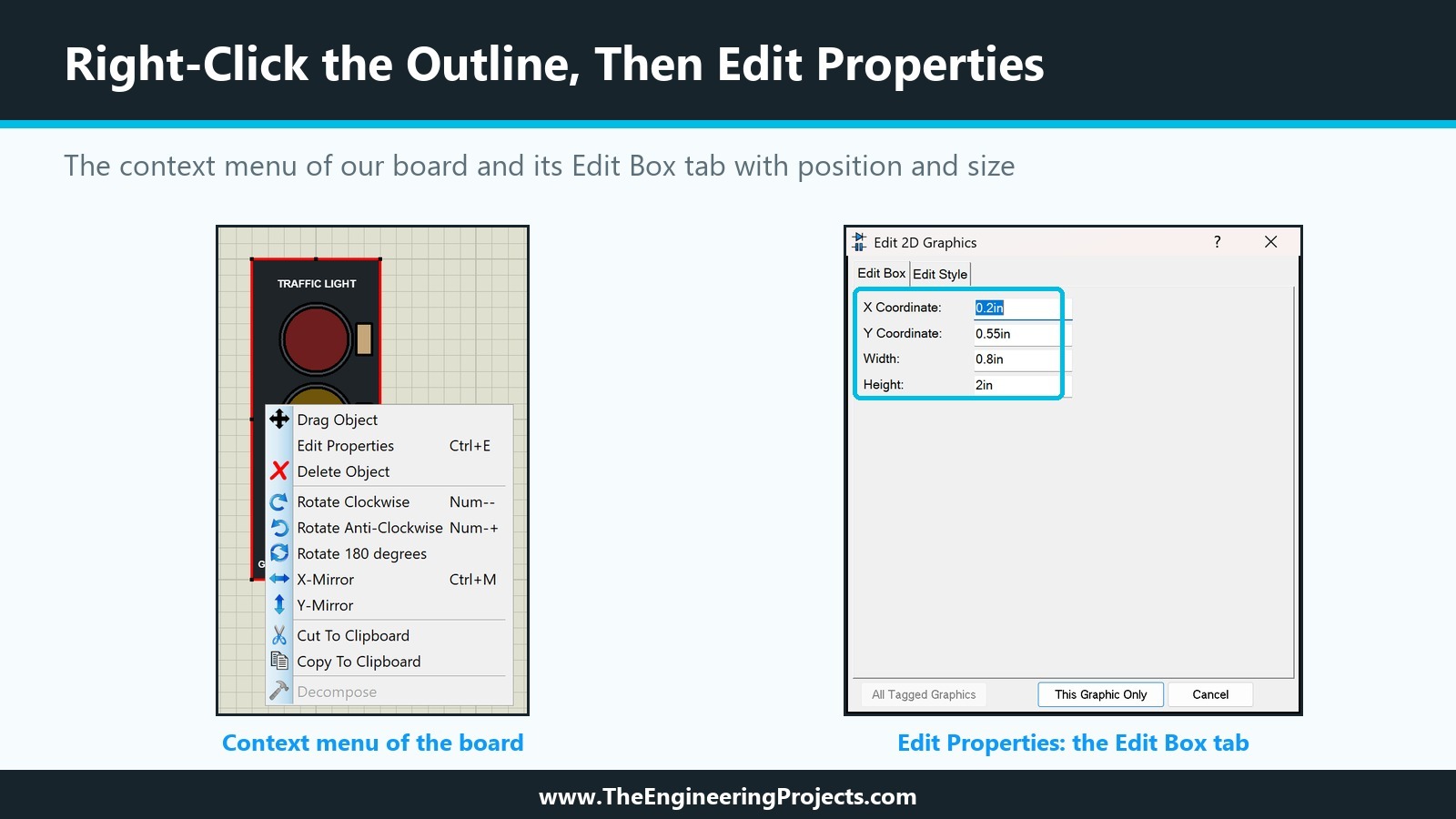
Edit Properties opens the Edit 2D Graphics dialogue, which has two tabs. The first tab depends on the object:
- Edit Box: X Coordinate, Y Coordinate, Width and Height.
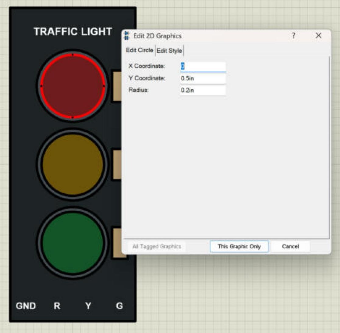
- Edit Circle: X Coordinate and Y Coordinate of the centre, and Radius.
The second tab, Edit Style, holds the colours and line settings; we use it below and explain it fully in the next tutorial. The fields accept units: type 230th for 230 thou or 0.5in for half an inch, and Proteus shows the values in inches when you open the dialogue again. The button This Graphic Only applies the change to the selected object; All Tagged Graphics applies it to every tagged graphic at once.
The Edit Box Surprise
One behaviour of the Edit Box tab is worth knowing, because it surprised us. X and Y are the position of the box's own origin, which is its centre when you first draw it. When you change Width or Height, Proteus keeps the bottom left corner where it is and moves the other edges, so the origin is no longer the centre. If you change the size and the position in the same edit, the box ends up shifted. You can see this in the picture above: our board is centred on (0, 0), yet its Edit Box tab shows X = 0.2in and Y = 0.55in, because we changed its size after drawing it and then moved it back into place. Our advice: draw boxes corner to corner on the grid, as in Step 1, and use the dialogue to check the values; if you do change a size, check the position again afterwards and correct it in a second edit.
Step 2: Draw the Lamp Rings with the Circle Tool
The three rings are circles with a radius of 230 thou, centred at (0, 500), (0, 0) and (0, -500). Because 230 is not on the 100 thou grid, we draw a circle with a radius of 200 and then type the exact radius.
- Select the 2D Circle tool.
- Click at (0, 500) for the centre, move the mouse until the status bar shows a radius of 200, and click again.
- Change to selection mode, right-click the outline of the circle and choose Edit Properties.
- On the Edit Circle tab, type
230thas the radius. X and Y show the centre and can stay as they are. - On the Edit Style tab, give the ring a dark grey fill (red 70, green 76, blue 82) and a black outline, then click This Graphic Only.
Unlike a box, a circle keeps its centre when the radius changes, so the radius can be edited freely.
How to Copy a Shape Exactly with Block Copy
We need two more rings exactly 500 thou below the first one. Drawing and styling them again would take time and risk small differences, so we copy the first ring with Block Copy, one of the block commands in the main toolbar.
- Select the ring in selection mode. We right-clicked its outline and closed the menu again; a selected object is drawn with a red outline.
- Click the Block Copy button in the toolbar. An outline of the copy now follows the mouse.
- Move the outline until it sits on (0, 0); it moves in steps of the current snap, so it is easy to place exactly. Click to place the copy.
- Move on to (0, -500) and click again for the third copy.
- Right-click on an empty part of the sheet to end Block Copy.
The copies keep the size and the colours of the original, so all three rings are identical. We use the same method for the lamps and the resistors below.
Step 3: Draw the Lamps on Top of the Rings
The lamps are circles with a radius of 200 thou at the same centres as the rings. Here we meet a basic rule of Proteus drawings: an object placed later is drawn on top of the objects placed before it. Our board was drawn first, so the rings appear on the board; the lamps are drawn after the rings, so they appear inside the rings. If you ever draw a filled shape in the wrong order, it hides what lies below it.
To keep the work tidy, we drew the first lamp in an empty area next to the board, gave it its fill colour, and then moved it into place by typing its centre into the Edit Circle tab: X = 0 and Y = 500th. The red lamp gets a dark red fill (110, 30, 30) and a black outline; these are the colours of a lamp that is off. Then Block Copy placed two copies at (0, 0) and (0, -500), and we changed only the fill colour of the copies: dark amber (110, 85, 10) for the yellow lamp and dark green (20, 85, 40) for the green lamp. The screenshot below shows the red lamp selected, with its Edit Circle values.
Step 4: Draw the Resistors with Snap 50th
Each resistor is a box of 100 by 200 thou on the right of its lamp, from x = 250 to 350. Those coordinates are multiples of 50, so we switch to Snap 50th with F2.
- Select the 2D Box tool and draw the first resistor from (250, 600) to (350, 400): the status bar confirms the two corners.
- Open Edit Properties and check the values: X = 0.3in, Y = 0.5in, Width = 0.1in, Height = 0.2in.
- On the Edit Style tab, give it a beige fill (196, 166, 120) and a black outline.
- Block Copy it twice, 500 thou down each time, and check the copies: X = 0.3in, Y = 0 and Y = -0.5in.
Step 5: Add the Title and the Pin Names with the Text Tool
Text completes the drawing. Select the 2D Text tool and click where the text should go; the Edit 2D Graphics Text dialogue opens at once.
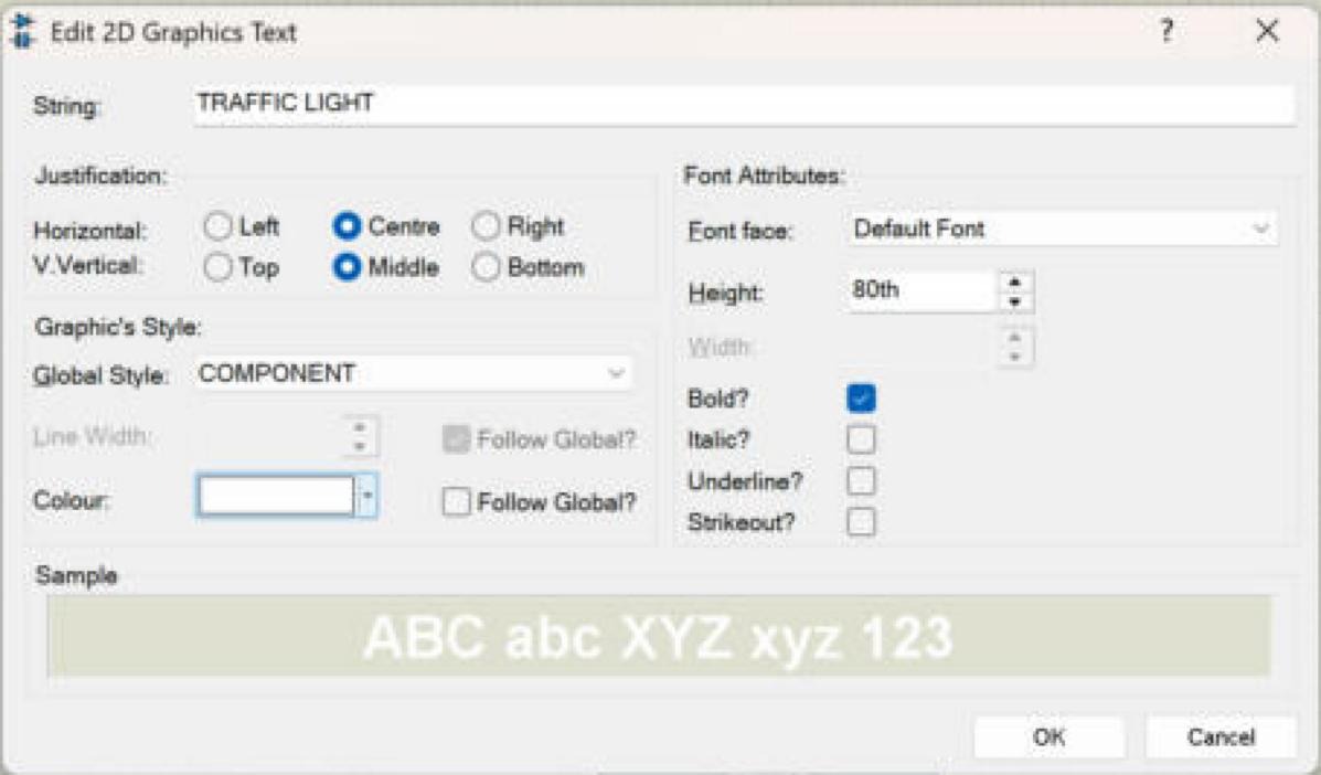
The dialogue has everything a label needs:
- String is the text itself.
- Justification decides which point of the text lies at the place you clicked. With Horizontal = Centre and Vertical = Middle, the click point becomes the centre of the text, which makes centring labels on a board easy.
- Graphic's Style holds the global style (COMPONENT) and the colour with its Follow Global box.
- Font Attributes hold the font face, the height and the Bold, Italic, Underline and Strikeout options.
For the title, we clicked at (0, 850), typed TRAFFIC LIGHT, chose Centre and Middle, a height of 80th and Bold, unticked Follow Global for the colour and chose white. For the pin names, we clicked at (-300, -900), (-100, -900), (100, -900) and (300, -900) and typed GND, R, Y and G with a height of 70th, bold and white. Each pin name now sits exactly above the place where its pin will be attached in a later tutorial.
Step 6: Give the Board Its Colours
The board still has the default COMPONENT colours. Right-click its outline, choose Edit Properties and open the Edit Style tab. Untick "Lock controls to global style's current settings", untick Follow Global for the line colour, the fill style and the fill colour, choose a solid fill with the colour (31, 36, 40) and a black line. The board turns black, and the lamps, resistors and text stand out on it, as in the picture at the top of this tutorial. The next tutorial explains each of these settings.
The Complete Drawing Log
Here are all fifteen objects of our drawing with the values we entered, in the order in which they were placed. If your drawing looks different, compare it line by line with this log.
TRAFFIC LIGHT MODULE - DRAWING LOG (values as entered in Edit Properties)
Units: th = thou, in = inch (1 in = 1000 th). Origin: board centre.
Order of placement = order of drawing: later objects are drawn on top.

#  Object      Tool    Position (X, Y)      Size                 Fill colour (R,G,B)  Line
1  Board       Box     corners -400th, 1000th and 400th, -1000th 31, 36, 40      black
2  Ring red    Circle  centre 0, 500th      radius 230th         70, 76, 82           black
3  Ring yel.   Circle  centre 0, 0          radius 230th         70, 76, 82           black
4  Ring grn.   Circle  centre 0, -500th     radius 230th         70, 76, 82           black
5  Lamp red    Circle  centre 0, 500th      radius 200th         110, 30, 30          black
6  Lamp yel.   Circle  centre 0, 0          radius 200th         110, 85, 10          black
7  Lamp grn.   Circle  centre 0, -500th     radius 200th         20, 85, 40           black
8  Resistor    Box     centre 300th, 500th  W 100th, H 200th     196, 166, 120        black
9  Resistor    Box     centre 300th, 0      W 100th, H 200th     196, 166, 120        black
10 Resistor    Box     centre 300th, -500th W 100th, H 200th     196, 166, 120        black
11 Title       Text    centre 0, 850th      height 80th, bold    white text "TRAFFIC LIGHT"
12 GND label   Text    centre -300th, -900th height 70th, bold   white
13 R label     Text    centre -100th, -900th height 70th, bold   white
14 Y label     Text    centre 100th, -900th  height 70th, bold   white
15 G label     Text    centre 300th, -900th  height 70th, bold   white

Copies: rings 3-4, lamps 6-7 and resistors 9-10 were made with Block Copy,
moved 500th down each time; only the fill colour of lamps 6 and 7 was changed.
Useful Tips for Drawing Components in Proteus
- Draw in layers, bottom first. Later objects cover earlier ones, so place the board first and the details last.
- Right-click the outline. Filled shapes are selected by their outline, not by their inside.
- Type the fine values. Draw roughly on the grid and type exact radii, sizes and centres into Edit Properties.
- Copy instead of redrawing. Block Copy keeps size and style identical and moves in grid steps.
- Draw new shapes in free space. Styling a shape away from the others avoids selecting the wrong object; move it into place afterwards by typing its centre.
- Check with the dialogue. After each shape, open Edit Properties and compare the values with your plan.
- Save often. Save the drawing as a project before you turn it into a device; we saved ours as Traffic Light Module.
Common Mistakes When Drawing in Proteus
| Problem | Cause | Solution |
|---|---|---|
| Right-click opens the sheet menu instead of the shape menu | The click was inside a filled shape | Right-click exactly on the outline |
| A box moves away after its size is changed | Width and Height grow from the bottom left corner | Change the size first, then correct X and Y in a second edit |
| A shape hides the details below it | It was placed after them | Delete and redraw it before the details, or redraw the details |
| A value is rejected as not valid | Old text was left in the field | Select all text in the field before typing the new value |
| A shape lands slightly off the plan | The snap was too coarse or too fine | Check the snap (F2, F3) and the coordinate display before clicking |
In the Next Tutorial
Our Traffic Light Module now exists as a drawing in Proteus. In the next tutorial, How to Make a Realistic Component in Proteus, we will look closely at graphics styles: the difference between global and local styles, the Follow Global settings, fill styles, line widths and colours, and how they make a drawing look like a real board while keeping the rest of a schematic consistent.
FAQ
Which tools does Proteus have for drawing a component?
The 2D graphics tools: line, box, circle, arc, path, text, symbol and markers. They are in the lower part of the mode toolbar of the schematic editor.
How do I set an exact size for a box or circle in Proteus?
Right-click the outline of the shape, choose Edit Properties and type the values on the Edit Box or Edit Circle tab, for example 230th or 0.5in. Click This Graphic Only to apply them.
Why does my box move when I change its width in Proteus?
Proteus keeps the bottom left corner fixed when the width or height changes, while X and Y describe the box's own origin. Change the size first, then check and correct the position.
How do I put one shape on top of another in Proteus?
Place it after the other one. Objects placed later are drawn on top of objects placed earlier.
How do I centre text on a component in Proteus?
Set the justification of the text to Centre and Middle; the point where you click then becomes the centre of the text.
Which graphics style should I use for a new component?
The COMPONENT style, as the help recommends. Colours that must stay fixed, such as a black board, are set as local values on the Edit Style tab.
That is all for today. Our module is drawn; next time we make it look its best. If you have any questions, ask in the comments. Take care.
Comments
0