Build an IoT-Based Weather Station in Raspberry Pi 4

Welcome to the next tutorial in our Raspberry Pi 4 programming course. In the previous tutorial, we learned how to automate your home with a Raspberry Pi and Bluetooth Low Energy. We found that using a Raspberry Pi 4 and Bluetooth Low Energy (BLE), users may command their household appliances from their smartphone or a web interface, and the Pi 4 will carry out the commands. This allows for a versatile and adaptable method of managing lights, thermostats, and smart plugs.

However, this Internet of Things (IoT) project aims to create a real-time Raspberry Pi weather station that displays the current humidity, temperature, and pressure values via an LCD and an online server. With this arrangement, you can track the local climate from any location in the globe over the internet and see what the weather is like right now and how it has changed over time via graphs.

The original Weather Station equipment is a HAT for the Pi that 4 incorporates several sensors for measuring the weather. It is intended for classroom use, where students can use the included materials to build their weather stations. In terms of both electronics and code, this is an advanced project. So before making any purchases, ensure you've read the entire project.

Components

  • A Raspberry Pi

  • WiFi dongle

  • A BME280 pressure, temperature, and humidity sensor

  • A DS18B20 digital thermal probe 

  • Two 4.7 KOhm resistors

  • 5mm-pitch PCB mount screw terminal blocks

  • A breadboard, jumper wires

  • An anemometer, wind vane, and rain gauge

  • Two RJ11 breakout boards (optional)

  • An MCP3008 analog-to-digital converter integrated circuit

  • Weatherproof enclosures

What will you make

Installation for measuring and recording atmospheric conditions and environmental variables in a specific area. Starting with a breadboard and some jumper wires, you'll design and construct a working model of a weather station. After you've gotten the prototype up and running and tested, you can create a more permanent version for use in the real world.

Software

This weather monitoring system runs on the Oracle Raspberry Pi. While installation is not required, you will use Python's many valuable tools. Start a new Terminal window and enter:

git clone https://github.com/RaspberryPiFoundation/weather-station

The BME280 Python library:

sudo pip3 install RPi.bme280

MariaDB is a database server software that:

sudo apt-get install -y mariadb-server mariadb-client libmariadbclient-dev

Sudo pip3 install mysqlclient

Building the circuit

Wireless connectivity

Your weather station will require an internet connection to transmit data to a location where it can be seen and analyzed. WiFi is the most convenient option; however, an Ethernet connection can be used if necessary.

Make a weather station HAT.

Compared to the "through-hole" connections used in many other digital manufacturing kits, stripboard connectors can be more challenging to solder. However, the plated through-hole contacts on the prototyping HATs for the Raspberry Pi make them much more convenient.

If you have an Adafruit Perma-Proto HAT Kit, you can build a weather station like the one in the following circuit schematic. If you're using nonstandard parts, you have some flexibility in arranging everything.

Things to note about this circuit diagram

Female headers represent the six pins found on the two RJ11 breakout boards so as not to obstruct the view.

Using this diagram to construct a circuit on a breadboard will call for a slightly unconventional method of thought. As the PTH connections are continuous throughout the board, you can route and join wires and components from either side.

With two 2-pin male connectors, as seen in the image above, the BME280 sensor can be easily attached to various devices. The sensor can then be placed in a dedicated housing, simplifying assembly. But, after passing the wires from the sensor through the grommets or glands designed to keep water out, you could solder them straight to the HAT.

Assembly

You should add a weather sensor to the board and test it individually before moving on to the next stage.

Initiate by soldering the 40-pin header to the Adafruit board.

Connect the SCL & SDA pins in the upper left and the 3V & GND pins using two 2-pin male connectors you have soldered in place.

To use the BME280 sensor, attach the HAT to the Pi and plug in the sensor's pins.

Power up the Pi and verify the BME280 sensor is functional by running the bme280 sensor.py program you created.

  • The DS18B20 probe's wires should be connected next. Again, use screw terminals on the breadboard. If you look closely, you'll see that one of the RJ11 breakout boards has some spare pins you may use on the proto-board. While the rain gauge only uses the connector's two center pins, the two on either side are available as screw terminals, allowing you to economize on floor space cleverly.

  • Turn off the power and take off the HAT from the Pi.

  • Install a resistor with 4.7K ohms of resistance in the bottom section by soldering it there. If possible, seat the resistor so that it is flush with the top of the Adafruit board and not protruding upwards; this will allow your RJ11 breakout board to rest immediately above it.

Make two more wire connections to the GND rail at the bottom.

  • Using longer cables, attach the GPIO pin breakout connectors (GPIO 4, 6) to the 3V rail. Again, it would be best if you positioned these at the base of the RJ11 breakout board. Since the HAT is hollow at its base, the wires can be soldered through from underneath. Either side of the HAT can be used as long as the appropriate holes are joined.

  • A smart option is to move the 3V rail connection to the back of the board, as doing so will avoid it going through a "busy" area on the top.

  • Get the RJ11 breakout board ready. It's essential to be careful around the sharp edges of the pre-soldered components on these breakout boards. Carefully snip off the protruding bits of solder using side cutters to prevent the peaks from generating shorts when soldered into the Adafruit board. Wrapping a thin piece of insulating tape around them is also a good idea for added protection.

  • Male pins required to connect to an Adafruit board are not included with some models of the smaller panels. These may first require soldering onto the breakout board. When soldering pins onto the Adafruit board, make sure the shorter end of the pin is touching the board.

Be sure the RJ11 breakout board's pins are inserted into their corresponding holes on the Adafruit board before soldering it. Avoid getting the RJ11 socket too hot, or the plastic will melt. When the HAT is attached to the Raspberry Pi, the long pins on the breakout board will connect to the video output via the Pi's HDMI connector. For this reason, you should either shorten them or insulate the HDMI port's top to avoid a short.

  • The DS18B20 sensor must be connected to the breakout board's screw terminals, as shown below.

  • To reattach the HAT to the Pi, you must take great care. First, ensure the Adafruit board's soldered connections aren't touching any of the Pi's top components before turning the power on. If they are, the relevant pins or wires should be shortened.

  • Start the ds18b20 therm.py script on your Pi after powering it on and testing the DS18B20 sensor.

  • Hook up the RJ11 cable from your HAT to the rain gauge.

Put your custom rainfall.py routines to the test and see if the rain gauge measures precipitation.

Currently, the MCP3008 ADC must be integrated. The IC could be soldered directly into the Adafruit board, but a DIP/DIL IC socket would be preferable. This lessens the potential for IC damage and facilitates future component swapping.

Take out the HAT & solder the connector to the Adafruit board, where the MCP3008 IC is depicted.

Connect the IC and the additional RJ11 breakout board to the power supply and ground using five short lengths of wire.

Add the remaining GPIO connections using the longer wire strips. You can route these connections on the top or bottom of the board, though it may be more difficult to solder the GPIO pins near the black plastic of the female connector on the bottom. Wind vane wiring requires just two more wires.

The other 4.7K ohm resistor must be soldered in place.

Next, connect the other RJ11 breakout board, ensuring no short circuits are created by the board's pins, which can be particularly dangerous if they are sharp or excessively long.

  • Place the MP3008 IC carefully into the socket. You should gently fold the legs inward before they fit into the socket without getting squished by the bulk of the chip.

  • It's time to put the HAT back on the Pi. Make sure that the Adafruit board's soldered connections are not making contact with any of the Pi's uppermost components. Cut off any excess wires or pins.

  • Connect the RJ11 cable from the wind sensors and run the wind direction byo.py and wind.py tests you created to see how well they work.

  • The HAT you made for the weather should now be completely functional. So check it out using the final, fully functioning version of the application we'll cover in this tutorial.

Any Weather Station must include sensors for measuring relative humidity, temperature, and barometric pressure.

We employed a DHT11 temperature/humidity sensor and a BM180 pressure sensor module. The LCD screen on this Thermometer with a Celsius scale and Humidity meter with a percentage scale also shows the current barometric pressure in millibars or hPa (hectopascal). All of this information is uploaded to the ThingSpeak server, which can be viewed in real-time from any location with an internet connection. Towards the end of this guide, you'll find a demonstration video and a Python program.

Humidity, temperature, and pressure

Digitally measuring temperature, humidity, and barometric pressure, the BME280 sensor is an all-purpose instrument. Several breakout boards from well-known brands, like Adafruit and SparkFun, feature it. The Adafruit package is assumed for this tutorial; however, the procedures should translate well to other distributions. First, ensure you're using the correct I2C address; in the code below, we're using 0x77, the address for Adafruit models. However, other versions may use a different address (0x76).

As illustrated in the above diagram, connect the sensor to the Pi.

The extra pins (such as SDO or CSB) on some breakout boards are rarely used but are available for those who want them.

Please make a new Python file and save it in the /home/username/weather-station/bme280 sensor.py directory. Then, substitute your Raspberry Pi username for the username in the following code.

import bme280

import smbus2

from time import sleep

port = 1

address = 0x77 # Adafruit BME280 address. Other BME280s may be different

bus = smbus2.SMBus(port)

bme280.load_calibration_params(bus,address)

while True:

    bme280_data = bme280.sample(bus,address)

    humidity  = bme280_data.humidity

    pressure  = bme280_data.pressure

    ambient_temperature = bme280_data.temperature

    print(humidity, pressure, ambient_temperature)

    sleep(1)

Now put the code to the test by letting out a big sigh upon the sensor while the program is running. Humidity readings (and perhaps temperature readings) ought to rise. You can quit the Python shell by pressing ctrl+c after testing the code. If the sensor is recording reasonable values, you can adapt the software to be utilized as a part of the more extensive weather station system. Change the while True loop to a call to a read all() function that sequentially returns the current humidity, pressure, and temperature.

Ground temperature

When it's cold outside, the BME280 will read the air temperature, which may be much higher than the ground temperature. Indicating the presence of ice or frost in the winter using a thermal probe inserted into the soil is an excellent supplement to standard temperature measurement. The Oracle Pi 4 Weather Station utilizes the Dallas DS18B20 temp sensor in several configurations, including a waterproof heat probe version.

Wiring up the sensor

Since the DS18B20 typically only has three bare wires, prototyping and testing the sensor is a breeze with PCB mount screw connector blocks that can be connected to breadboards. Connect the DS18B20 to the circuit as depicted in the image. Note that you're connecting the breadboard's 3.3 Volt and Ground wires along the board's edge. They will be necessary for expanding the circuit to accommodate more sensors.

Open the file /boot/config.txt:

sudo nano /boot/config.txt

Edit it by:

Then open /etc/modules.

sudo nano /etc/modules

Include the following lines at the end of the document:

w1-gpio

w1-therm

Now restart the Raspberry Pi. Then load up ds18b20 therm.py from /home/pi/weather-station/ in IDLE. The Python prompt should now display the current temperature.

Submerge the probe in ice water and restart the process. The newly reported temperature should be lower if you weren't already operating in a freezing room.

Air quality

The Figaro TGS2600 sensor was initially included in the Oracle Raspberry Pi 4 Weather Station package. We've had good luck with the first set of devices integrated into the Station HAT, but the most recent devices we've tried have proven difficult to adjust and have given us conflicting results. While they work well for monitoring broad changes in atmospheric gases, their specific application in a personal weather station has yet to be recommended. As soon as we settle on a budget air quality monitor, we'll update this article with our findings.

Active mechanical sensors

All the electronics you've employed as sensors until now are passive; they observe and record data. However, active machines directly interacting with the environment must measure rainfall and wind speed/direction.

The initial Oracle Station kit used standard components in many home weather stations, such as wind and rain sensors. For their durability and dependability, these sensors are highly recommended. The data sheet has more info about the sensors' dimensions and build quality.

Connectors

The RJ11 connectors that come standard on these sensors (they resemble a regular telephone jack) are solid and unlikely to become accidentally dislodged, ensuring that your weather station continues to function despite the wind.

There are three ways to hook them up to your Pi:

  • You can use screw terminals or solder to join the wires after severing the male RJ11 connectors.

  • Utilize female RJ11 connectors, which are challenging to work with on breadboards but can make for a rock-solid connection when soldered to a PCB for use in a fixed weather station.

  • While RJ11 breakout boards are great for prototyping, their larger counterparts may need to be more practical for permanent installations.

The smaller ones typically have solderable pins that can be connected to a stripboard or a prototype HAT. These smaller breakout boards will be used in the following assembly instructions to build a permanent hardware solution.

Wind speed

The anemometer's three arms capture the wind, culminating in scoops and rotation. The first Oracle Weather Stations employed anemometers with a small magnet connected to the underside to measure wind speed.

This illustrates a reed switch, a clever piece of electronics triggered by the magnet at two rotation points.

In the presence of a magnet, the reed switch's internal metal contacts will contact one another. This switch's electronic operation is identical to a button attached to the Raspberry Pi; as the anemometer spins, the magnet briefly closes the circuit formed by the reed switch. Because of this, the rate at which the anemometer spins can be determined by counting the signals it receives from the reed switch.

The reed switch generates a signal that may be picked up on a GPIO pin whenever it is actuated. The sensor will send out two discernible signals for every entire rotation of the anemometer. You can figure out how fast the wind blows by tracking and timing these signals.

Python provides a plethora of options for achieving this. For example, a button-like sensor can be counted using the gpiozero library. The gpiozero library, for instance, can be used to count the number of times a sensor was "pressed" to simulate its use as a button.

It's common for consumer anemometers to have two cables. Pair them up by connecting one to GPIO 5 and another to the ground. The anemometer connects to pins 3 and 4 on standard RJ11 breakout boards in the cable's center.

After you connect the anemometer, your connection should resemble this:

Start IDLE, make a new Python file named "wind.py," and save it to the /home/pi/weather-station directory. Insert the code below to assign GPIO5 to the Button class and use GPIO0's Button methods. Create a counter named wind count to keep track of how many times the wind has shifted directions.

from gpiozero import Button

wind_speed_sensor = Button(5)

wind_count = 0

Now you can set a function to be executed anytime a turn of the anemometer triggers the pin.

def spin():

    global wind_count

    wind_count = wind_count + 1

    print("spin" + str(wind_count))

wind_speed_sensor.when_pressed = spin

You can now exit the editor and run the code. The anemometer's accuracy can be checked by manually rotating its arms. You should be able to see your code being executed in the Python shell, with the count variable increasing by two with each revolution.

The anemometer's signals can now be counted, allowing you to determine the wind speed.

Calculating wind speed

As the anemometer generates two signals per rotation, you may determine the total number of sensor revolutions by dividing the total number of signals by two. The wind speed can therefore be determined from this:

Speed = distance / time

The distance covered in a given time period is a necessary input when attempting to determine velocity. Time is easily quantified by counting the occurrences of a signal over some predetermined interval, say five seconds.

One cup will travel a distance according to the product of the number of revolutions times the radius of the circle:

Speed = (rotations * circumference) / time

If you know a circle's diameter or radius, you can figure out the circumference.

To determine the diameter of the circle produced by the anemometer, measure the radius of the cups. Knowing the radius, you can calculate the circumference using the equation 2 * pi * radius. Keeping in mind that a complete rotation produces two signals, you will need to decrease the overall amount of signals detected by half:

Speed = ((signals/2) * (2 * pi * radius)) / time

Here are some code snippets based on the radius of 9.0cm, which is the size suggested for the anemometers used in the first Oracle Weather Station. If your anemometer's dimensions differ, make sure you adjust this value.

This formula can be used with the maths library in Python. If you took 17 readings from your anemometer for 5 seconds, you could figure out how fast the wind was blowing in this way:

import math

radius_cm = 9.0

wind_interval = 5

wind_count = 17

circumference_cm = (2 * math.pi) * radius_cm

rotations = count / 2.0

dist_cm = circumference_cm * rotations

speed = dist_cm / wind_interval

print(speed)

Remove the line from the spin method that prints it out to prevent the wind count value from being displayed.

Now you can use this equation to adjust your wind.py program so that it also determines the wind speed in cm/s).

Measurement units

The code currently uses a unit of measure equivalent to centimeters per second for the wind speed. Unfortunately, this could be more helpful; (km/h) is a more useful measurement.

Adjust your program to give wind speeds in kilometers per hour.

Calibration

An anemometer's accuracy can be verified using the information provided in the device's specification, which is often found in the manual. For example, according to the specifications for the suggested anemometers, 2.4 kilometers per hour is equivalent to one spin per second. Therefore, the same 2.4 km/h wind velocity should result from five rotations (ten signals) in five seconds.

Spin the anemometer five times in the first 5 secs after your program has started. What exactly is the stated wind speed?

You'll likely discover the value is off from what was expected. The anemometer factor is to blame for this discrepancy; it is the amount of wind energy that is dissipated whenever the arms rotate. An adjustment factor can be multiplied by the program's output to account for this.

Anemometers with this rating are 1.18 for the recommended models.

You need to change the final line of your calculate speed function so that it multiplies your speed in kilometers per hour by 1.18.

Correctly displaying the output in the appropriate units requires modifying the final print line of your code.

If you re-run the code, you will likely get a speed estimate closer to 2,4 kilometers per hour.

It will be helpful to reset the wind count variable to zero when putting the weather station together; therefore, implement that functionality now.

def reset_wind():

    global wind_count

    wind_count = 0

Wind gusts

The average and maximum wind speeds and any significant wind gusts are typically included in weather reports and forecasts. Whenever the wind is present, there is always the potential for a temporary but significant increase in wind speed, known as a gust. As the wind picks up momentum, it becomes easier to detect gusts. This occurs because the wind's force rapidly rises with increasing wind speed.

The inability of the air to move at a consistent pace along the ground is the usual source of gusts. Because of differences in surface friction caused by obstacles like plants, buildings, and elevation variations, wind speeds will vary across the landscape. This effect is more noticeable in lower-altitude air than in higher-altitude air. Because of this, gusts are produced as the wind flows more erratically along the ground. It takes fewer than 20 seconds for the average wind gust to pass.

Storing wind readings

With a fully functional weather station, you may measure the average wind speed over time, and the maximum speed experienced during that period (the gust). To do this, one can continuously take five-second readings of the wind speed, storing them in a buffer for later processing once every several minutes. In Python, lists are the appropriate data format for this task.

The wind.py file can be found in the /home/pi/weather-station directory; open it in IDLE.

Import the statistics libraries with a single line added at the very beginning.

import statistics

Next, just beneath the import lines, add the line below, which defines an empty list named store speeds:

store_speeds = []

Now, edit the while True loop to include a new one that continuously collects wind speed data and appends it to the previous tally. Then, statistics can be used to determine the average speed from the store speeds data set.

while True:

    start_time = time.time()

    while time.time() - start_time <= wind_interval:

        reset_wind()

        time.sleep(wind_interval)

        final_speed = calculate_speed(wind_interval)

        store_speeds.append(final_speed)

    wind_gust = max(store_speeds)

    wind_speed = statistics.mean(store_speeds)

    print(wind_speed, wind_gust)

Take note that time is being used. Start by using the time() to generate a variable named start time, and then use the while loop's inner check condition to see if the current time has progressed by more than the wind interval seconds.

Start executing your program. Just blow into the anemometer or manually spin it and observe the results.

Once you stop spinning, the anemometer's average speed will decrease while the second measurement will remain constant (because this is the highest gust produced). For the next steps, please follow our next tutorial on how to build an IOT-based weather station.

Conclusion

In this post, we learned the basics of using a Raspberry Pi as the basis for an Internet of Things-based weather station. In the subsequent session, we will learn how to develop the Python code that will bring our weather station circuit design to life.

Introduction to Raspberry Pi 5

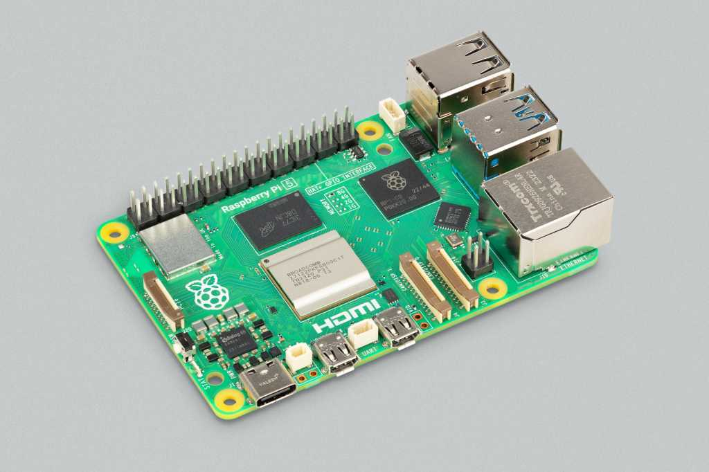
Hello everyone, I hope you all are doing great. In today's lecture, we will discuss one of the most advanced Embedded Microprocessors i.e. Raspberry Pi 5. At the time of this writing, Raspberry Pi 5 is the latest board designed in the Raspberry Pi series.

Raspberry Pi 5 is designed by a UK-based charity foundation named Raspberry Pi Foundation. Initially, these boards were designed for students and hobbyists but because of their compact design and advanced features, they became popular among embedded engineers, especially for IoT Systems. Raspberry Pi boards can be used for simple tasks i.e. word processing, web browsing etc., and in the complex fields of robotics, multimedia centers, home automation, etc.

In today's lecture, we will first discuss the basic features of the Raspberry Pi 5, its pinout, history, release date, price etc. in detail. After that, we will install the Raspbian Operating System on the Pi board and run it for the first time. So, let's get started:

Introduction to the Raspberry Pi 5

  • Raspberry Pi 5(abbreviated as RPi5), designed in the UK by Raspberry Pi Foundation, is the latest addition to the family of Raspberry Pi boards.

As compared to its predecessor(i.e. Raspberry Pi 4), it has a better CPU, memory, graphic performance, connectivity etc. that make it more powerful and better in performance. Similar to other boards in this series, the Raspberry Pi 5 is a credit card-sized board with an affordable price and low power consumption. By looking deep into its features, experts comment that it has a significant upgrade over the previous versions.

Before going forward, let's have a look at the evolution of Raspberry Pi boards from 1 to 5:

Evolution of Raspberry Pi Boards

The first Raspberry Pi board was introduced in 2012 for educational purposes to learn programming. This Pi board gained fame because of its simplicity, ease of use, and low cost. The first release was so successful that it sold out within hours, and according to reports, 40 million units were sold at that time. The huge success motivated the Raspberry Pi Foundation to design more models. Raspberry Pi 1 variants are as follows:

Raspberry Pi 1 Model A

Raspberry Pi 1 Model A has a 700 MHz ARM11 CPU and a Broadcom BCM2835 system-on-chip (SoC). 256 MB of RAM is present on this board, but it is no longer in production. 

Raspberry Pi 1 Model B

Raspberry Pi 1 Model B has a 700 MHz ARM11 CPU and 512MB of RAM. It has a better performance as compared to Model A and has two USB ports. This model is also not in production. 

Raspberry Pi 1 Model B+

Raspberry Pi 1 Model B+ is quite similar to its predecessor Model A in functionality, though it has an improved form factor.

Raspberry Pi 3 Model A+

It is a small and affordable board that has built-in WiFi and Bluetooth. It has 512 MB of RAM and an extended 40-pin GPIO header. It is an ideal option to use with a camera because of the CSI camera port.

Raspberry Pi 3 Model B and B+

Raspberry Pi was used extensively; therefore, Raspberry Pi presented these models. The Raspberry Pi 3 model B has a 1.2 GHz quad-core ARM Cortex-A53 CPU, and at that time, it was the ideal choice for IoT projects.

Moreover, the Model B+ had a slightly different structure and characteristics. It has a slightly more powerful processor. In this, the designers have taken more care of thermal management. 

Raspberry Pi 4

This is the most powerful board on the Raspberry Pi. It has a 1.5GHz quad-core ARM Cortex-A72 CPU and lower power consumption. The 8GB of RAM of this board makes it ideal for low-cost desktops, media centers, etc. This board has a 4K display and more RAM and processor speed, making it more useful for better desktop use. It is a better option for desktop replacement than the other predecessors of Raspberry Pi boards. 

Raspberry Pi Zero

It is the smaller and more versatile version of the Raspberry Pi. It has a 1GHz ARM Cortex-A53 CPU and a more powerful structure. It has a micro USB and Bluetooth 4.1. The Mini HDMI port and micro USB On-the-Go (OTG) port are the prominent features of this board. 

Raspberry Pi Zero W

This version has the same specs as the previous one, but it has built-in WiFi and Bluetooth. This made it perfect for the projects of IoT and related fields. 

Raspberry Pi Pico

This is a small board that is specially designed for small projects that use low power and require versatility. It has a 133 MHz dual-core ARM Cortex-M0+ CPU, and it is a microcontroller. It means it is not a full-fledged single-board computer but is designed for small projects and embedded system applications for low-level programming; therefore, it has only 264KB of RAM to accommodate the changes.

This is not the end of the list; there are multiple other boards, such as the Raspberry Pi 400 and Raspberry Pi Pico, that are also important to understand. The following table will show you the features and information about the Raspberry Pi boards:


Name of Board

Release Date

Processor

RAM

Special Feature

Raspberry Pi 1 Model A

February 2013

700MHz ARM11

256MB

N/A

Raspberry Pi 1 Model B

February 2013

700MHz ARM11

512MB

Two USB Ports

Raspberry Pi 1 Model B+

July 2014

700MHz ARM11

512MB

Improved Form Factor

Raspberry Pi 2 Model B

February 2015

900MHz quad-core ARM Cortex-A7

1GB

Improved Performance

Raspberry Pi 3 Model A+

November 2018

1.4GHz quad-core ARM Cortex-A53

512MB

Built-in Wi-Fi, Bluetooth, and CSI Camera Port

Raspberry Pi 3 Model B

February 2016

1.2GHz quad-core ARM Cortex-A53

1GB

Built-in Wi-Fi, Bluetooth

Raspberry Pi 3 Model B+

March 2018

1.4GHz quad-core ARM Cortex-A53

1GB

Improved Thermal Management

Raspberry Pi 4 Model B

June 2019

1.5GHz quad-core ARM Cortex-A72

2GB, 4GB, or 8GB

4K Display Support, USB 3.0, Gigabit Ethernet

Raspberry Pi Zero

November 2015

1GHz ARM11

512MB

Compact and Affordable

Raspberry Pi Zero W

February 2017

1GHz ARM11

512MB

Built-in Wi-Fi and Bluetooth 4.1

Raspberry Pi Pico

January 2021

133MHz dual-core ARM Cortex-M0+

264KB

Designed for Microcontroller Projects

Raspberry Pi 5

September 2023

2.4GHz quad-core ARM Cortex-A76

4GB or 8GB

Dual 4Kp60 HDMI display output, dual-band 802.11ac Wi-Fi, Bluetooth 5.0

Raspberry Pi 5 Release Date

Eben Upton, the co-founder of the Raspberry Pi Foundation, announced the release of the Raspberry Pi 5 at the annual event on September 28, 2023. At that time, some people were predicting that the release would be delayed because of the global chip shortage, but the Raspberry Pi Foundation proved them wrong. 

It seems that the mission of the foundation is to enhance the domains of Raspberry Pi projects because they have significantly improved the working of the board. The Raspberry Pi 4 was released in 2017, as expected by the users, and this board is significantly different from the previous version. We will discuss the features of the Raspberry Pi 5 in detail, but for now, you must know that embedded engineers, hobbyists, students, and professional electronic engineers were excited about this release. 

Raspberry Pi 5 Price

The Raspberry Pi 5 has two variants, i.e., the buyers have two options to buy and they have to pay according to the RAM:

  1. Raspberry Pi 5 4 GB RAM: 60$

  2. Raspberry Pi 5 8 GB RAM: 80$

These prices are relatively higher than the Raspberry Pi 4 with the same amount of RAM. These are the prices of boards only. To work with these boards, other components are also required. Here is the list of components required for the Raspberry Pi 5 functionalities, along with their prices:

Compulsory Components

Components

Specification

Price Range

Raspberry Pi 5 

4 GB RAM/ 8GB RAM

60$/80$ 

Power supply

3A 

$10-$20

Case

Different prices according to the material

$5-$25

Micro SD card

8GB storage

5$-10$

HDMI cable

Connection with monitor

5$-10$

Additional Accessories

Keyboard and Mouse

Control the system

$10-$20

Network cable

Connection with internet

5$-10$

USB hub

Connection with multiple USB devices

5$-10$


The user can purchase these components from the Raspberry Pi Foundation or third-party retailers. Notice that all the components are not compatible with the Raspberry Pi 5; therefore, the users have to buy them. Here are the details of the essential components required for the Raspberry Pi 5.

Case of Raspberry Pi 5

The case of this board is similar to the previous case (the Raspberry Pi 4), but this time, the foundation has made a little change to elevate the thermal management and new usability. The case is integrated with a 2.79 (maximum) CFM fan. It has fluid dynamic bearings to provide better noise resistance and an extended lifetime. This fan is used to eliminate air through the 360-degree slot under the lid of the case. A four-pin JST connector is present on the board to connect it with the fan.

The size of the Raspberry Pi 5 is larger than other boards; therefore, the case is longer than the previous ones. Moreover, the retention feature of this case allows the user to insert the Raspberry Pi 5 board without removing the SD card. 

Remove the top of the case to stack multiple cases or mount HATs on the top of the fan. For this, there will be a requirement for spacers and GPIO header extensions. These cases are available in different materials that have varying prices according to the material. 

Active Cooler of Raspberry Pi 5

For users who do not want to have the case, an active cooler is designed to maintain the Raspberry Pi 5 temperature. This board is designed to handle a heavy workload, and if the user wishes to have it uncased, it is important to use the active cooler for the best performance. The board has two new mounting holes that place the active cooler in its fixed place. The connection of this fan is made with the same four-pin JST connector that we have mentioned before. 

Both the fans (active cooler and case fan) are effective in maintaining the temperature and exhausting the extra heat from the board, but the active cooler has better performance.

Power Supply for the Raspberry Pi 5

The official power supply for the Raspberry Pi 5 is a 27W USB-C PD. These are designed to work with the charger that provides 5 volts of power at 3 amps of current. This makes it compatible with many power supplies, but it is always advisable to use a 27W USB-C PD. The experts have analysed that using the specified power supply not only provides the long life of the board but is also responsible for lower power consumption and high-speed results. 

Camera and Display Cables on the Raspberry Pi 5

The Raspberry Pi 5 has a new MIPI connector to connect the cameras and other display devices. It's up to the user whether they want to use the third-party cameras here or the official camera launched by the Raspberry Pi. These are connected to the board through cables of different sizes and provide the versatility to use cameras with their boards. 

How to Interface Raspberry Pi 5 with System?

Once you have all the components that I have mentioned before, you are ready to use your Raspberry Pi 5. Here are the steps to follow:

  • Check for the microSD card’s slot and insert the card so that the Raspberry Pi 5 may have the memory.
  • Connect the HDMI cable to the HDMI slot of the Raspberry Pi 5, and the other end must be interfaced with the monitor so the display may work.
  • Connect the keyboard and mouse to the USB ports of the Raspberry Pi 5 so that you can control the functions.
  • Connect the power supply to the board.
  • Turn the power supply through the button.

Raspberry Pi 5 Specifications

The Raspberry Pi provides consistent improvements in every model it represents, and this foundation has proven this once again through this latest model. The structure and simplicity of this board allow the designers to provide better functionalities at a low cost as compared to other types of boards.

  • The processor on this board is faster than the previous one and can run on low power.
  • The foundation has worked on better video quality and display specifications.
  • It has memory options for 8GB, 4GB, 2GB, and 1GB, which means multiple memory options are present for the users.
  • The heart of this new board is its system on chip (SoC), which is Broadcom BCM 2712, which has a 4-arm cortex, hence its significantly better speed.
  • The GPU has remarkable performance, and it provides the best user experience.
  • On the right side of the board, there is a fan pin that can be directly connected to the fan without any need for extra cable.
  • Just like Raspberry Pi 4, it has Gigabit Ethernet. But, to provide connectivity for a great number of devices, it has 2 USB 2.0 ports and 2 USB 3.0 ports. These ports are better in functionality as compared to the previous versions.
  • Some other connectors include USB C power (5V and 5A), UART connector real-time battery connector, 4 pin power Ethernet connector.
  • There are 2 MIPI (CSI and DSI) ports which are the latest changes in Raspberry Pi boards. For the existing camera, it has separate 200mm/300mm/500mm ports.

The Raspberry Pi 5 PCIE 2.0 connector allows this board to connect with other hardware and transfer 500 MBs per second. Hence, this board can easily be connected with other hardware with the ribbon connector and there is no need to add the additional cable or port. 

Here are some basic specifications of the Raspberry Pi 5 that every user must know before buying it:

Component

Specification

Central Processing Unit (CPU)

Broadcom BCM2712 2.4GHz quad-core 64-bit Arm Cortex-A76 CPU that comes with cryptography extensions that have 512KB per-core L2 caches and a 2MB shared L3 cache for best performance. 

Graphical processing Unit (GPU)

VideoCore VII GPU supports OpenGL ES 3.1 AND Vulkan 1.2

Display Output

Dual 4Kp60 HDMI display output, which has HDR support

Video Decoder

High-quality 4Kp60 HEVC decoder

Memory

LPDDR4X-4267 SDRAM (4GB and 8GB SKUs available at the time of launch)

Wireless Connectivity

Amazing dual-band 802.11ac Wi-Fi, Bluetooth 5.0 / Bluetooth Low Energy (BLE)

Storage

microSD card slot with support for high-speed SDR104 mode

USB Ports

2 × USB 3.0 ports supporting simultaneous 5Gbps operation, 2 × USB 2.0 ports

Ethernet

Gigabit Ethernet with PoE and support (requires separate PoE and  HAT)

Camera/Display Interfaces

2 × 4-lane MIPI camera/display transceivers

Peripheral Interface

PCIe 2.0 x1 interface for fast peripherals

Power Supply

5V/5A DC power via USB-C with Power Delivery support

GPIO Header

Raspberry Pi standard 40-pin header (we will discuss these in detail)

Real-time Clock (RTC)

Powered from an external battery

Raspberry Pi 5 GPOI header Pinouts

The Raspberry Pi 5 has a 40-pin GPIO header that can be used to connect to a variety of devices, including sensors, actuators, displays, and other microcontrollers. The following table shows a description of each pin on the Raspberry Pi 5 GPIO header:


Range

Pin Name

Description

1-6

3.3V, 5V, Ground

Power and ground pins

4-17

GPIO 17-27

General-purpose input/output pins

8-11

GPIO 7-10

General-purpose input/output pins

14-16

GPIO 14-16

General-purpose input/output pins

19-21

GPIO 20-21

General-purpose input/output pins

22-23

GPIO 5-6

General-purpose input/output pins

24-25

Ground

Ground pins

26-27

SPI CE0, SPI MISO

SPI bus pins

28-30

SPI MOSI, SPI SCLK

SPI bus pins

32-33

I2C SDA, I2C SCL

I2C bus pins

34

UART RX

Receiving pin

35

UART TX

Transmitting pin

Features of Raspberry Pi 5

The following are the basic features of the Raspberry Pi 5:

  • The Raspberry Pi 5 has a powerful CPU with 2.4 GHz speed. As expected by the experts, the company has provided a faster and better CPU that can be used for complex applications such as machine learning and video editing. This was very difficult in the older versions. According to the foundation, they are expecting two to three times better performance.
  • The creators have added more RAM in this version to meet the need to run applications at the same time. So, the RPi5 can provide better performance even under heavy loads.
  • The RPi5 is made to meet the demand for high graphics for gamers and video editors. It has a better GPU that is best for high-quality graphic needs.
  • The HDMI of the RPi5 has made it possible to connect two monitors at a time. This lets the user connect two 4K monitors at 60 fps at a time and create a home theatre, get the best gaming experience, or provide the best graphic design experience.
  • The power over ethernet (PoE+) allows the user to provide the power to their Raspberry Pi 5 with the ethernet instead of the external power supply. This allows users to use this board easily, even in remote locations.

Raspberry Pi 5 vs. Raspberry Pi 4

The huge success of the Raspberry Pi 4 has made the foundation confident enough to present a better version. There is a four-year gap between the releases of these boards, and during these years, RPi4 has gained great popularity. Here are some key differences among these models:


Feature

Raspberry Pi 5

Raspberry Pi 4

Remark

CPU

2.4 GHz quad-core 64-bit Arm Cortex-A76

1.5 GHz quad-core 64-bit Arm Cortex-A72

Faster CPU for demanding applications

GPU

VideoCore VII

VideoCore VI

More powerful GPU for graphics-intensive tasks

Display output

Dual 4K 60 Hz HDMI

Dual 4K 30 Hz HDMI

Higher refresh rate for smoother video playback

Power over Ethernet (PoE)

Yes

No

Power the Raspberry Pi over an Ethernet cable

Real-time clock

Yes

Yes

Keep track of time even when not connected to the internet

Power button

Yes

No

Turn the Raspberry Pi on and off without disconnecting the power supply


These are the major differences, and these make the Raspberry Pi 5 better than the Raspberry Pi 4. No doubt, the Raspberry Pi 4 has made its place in the hearts of multiple users, but it seems that the Raspberry Pi 5 is going to be more powerful and famous than the previous version. 

The following are some specifications that are the same on both these boards:

  • GPIO pins
  • USB ports
  • Network capabilities

Applications of Raspberry Pi 5

Since Raspberry Pi 5 is new right now, there is no extraordinary project evidence, but by looking at the specifications, we can suggest the best projects and applications of this board. Here is the list of the main categories of applications:

Home Media Center with Raspberry Pi 5

The Raspberry Foundation presented this board with the best video-supporting features. The dual 4Kp60 HDMI display output and a 4Kp60 HEVC decoder allow users to create their own home media centres with the help of this small board. Following are some important components from the house of Raspberry Pi required for this project:

  • HDMI Cable: These are used to connect the Raspberry Pi 5 to the TV or monitor. 

  • MicroSD Card: At least 32GB card is required to store movies, TV shows, operating systems, etc. 

  • USB Keyboard and Mouse: These will help with navigation on the system.

  • Media Center Software: LibreELEC or OSMC are popular choices for such types of applications.

Game Station with Raspberry Pi 5

The Raspberry Pi 5 is a single-board computer, and a great number of gamers are attracted to its VideoCore VII GPU and support for OpenGL ES 3.1 and Vulkan 1.2. These make it most suitable for the latest games because it provides a smooth experience even with the high-quality graphics. The users seem satisfied because it provides a versatile gaming experience. The smooth flow of the game is always required for the best user experience, and the improved graphics and high resolution of videos make it possible. As we have mentioned before, the high-speed processor of this board is more than enough to deal with the heavy load.

Home Automation with Raspberry Pi 5

The latest technology has made all the devices intelligent, and the connected network of these devices is a big step toward life automation. The Internet of Things (IoT) has made life easier and saved a lot of time; therefore, people are moving towards applications like home automation. The Raspberry 5 is equipped with dual-band 802.11ac Wi-Fi, Bluetooth 5.0/BLE capabilities, and the high-speed processor allows the users to have the luxury of home style with this small board. 

Magic Mirror with Raspberry Pi 5

Magic Mirror is an open-source project on a Raspberry Pi board that seems like a simple mirror, but with the help of different components, this can be turned into a monitor-like screen that can show different types of information on the mirror. Raspberry Pi 5 can design this mirror in such a way that users may see information like calendars, weather forecasts, Google Photos, YouTube videos, etc. In short, this project converts the simple mirror into a computer screen, and the user can still see the reflection on it and control the display. The following are the basic components of this project:

  • A two-way mirror that shows the reflection to the user but also allows the digital information to blink on it.

  • A monitor is required to be placed behind the mirror. This may be any old or new version that simply shows the output on the screen. 

  • The Magic Mirror software is used to control the working of all the elements on the screen. This provides control to the user and connects the mirror, Raspberry Pi 5 board, and monitor together to provide the final result. 

  • When the user wants to see the additional features or wants to upgrade the system, they simply have to use the additional modules related to the functionality. 

Educational Assistance with Raspberry Pi 5

The main purpose of this Raspberry Pi board is to provide an easy and affordable way to learn computer science projects. The Raspberry Pi 5 board provides better help to students of computer programming and electronics because it is perfect for STEM projects. 

The advanced features of this board allow the students to work on the latest technologies without the need for a full computer system. The Raspberry Pi 5 is a powerful tool to create and test the latest projects. 

Raspberry Pi 5 for Machine Learning

The Raspberry Pi 5 has the latest features that make it perfect for working in the most trending field of programming and engineering, which is machine learning and its applications. In addition to the other features we have just mentioned, this board has two camera serial interfaces (CSI) and peripheral component interconnect express (PCI) for the AI accelerator. With these two, the Raspberry Pi 5 board is ready to serve the project requiring high processing power and two serial interfaces. This was not possible with the previous versions of RPi boards. This is the need of the time because students are now attracted to machine learning, computer vision, and related fields.

Conclusion

The Raspberry Pi 5 is the latest credit card-sized board from the Raspberry Pi Foundation. It is released to help hobbyists, students, teachers, and programmers create projects on embedded systems, IoT, home automation, game stations, home media centers, magic mirrors, and many other kinds of projects in easy and affordable ways. This board has many exceptional features that will allow the users to get high-speed, high-quality images/videos, dual display device connections, etc. The users have to buy the board, case, power supply, and SD card to use this board. It is a relatively expensive board, but its features are worth it. 

In this article, we have seen the specifications and pinouts in detail and compared the structure with the Raspberry Pi 4. We also discussed the connection procedure for this board. I hope this was a useful study for you, and if you need any type of help, you can ask for it in the comment section.

Control Home Appliances with RPi4 BLE

Welcome to the next tutorial of our raspberry pi 4 tutorial. In the previous tutorial, we learnt how to interface a gas sensor with a pi 4. However, in this tutorial will cover how to automate your home with a Raspberry Pi and Bluetooth Low Energy. To automate a home means to mechanize its environment, including the appliances within it. To that end, we've designed an intelligent lamp whose functionality can be adjusted from afar via a companion mobile app.

Using your smartphone, you'll be able to manage a variety of household gadgets. The following code demonstrates using a mobile device as a remote controller for a Raspberry Pi's GPIO pins. (Or another BleuIO Dongle).

Instructions Requirements

The recently introduced Raspberry Pi 4 will serve as our testbed, but the lessons learned here should apply to any Pi board. You'll need these things if you want to follow along:

  • Raspberry Pi 4B

  • Micro SD Card 

  • Micro SD Card Reader

  • Power Supply

  • Ethernet Cable

As a result of its low price and excellent integration, the Raspberry Pi has quickly become a popular platform. This board has Wi-Fi, Ethernet, and Bluetooth Low Energy (BLE) connectivity.

Bluetooth functionality on the Raspberry Pi is variant-specific.

The Raspberry Pi has a built-in Wi-Fi and Bluetooth Low Energy chipset so that you can connect wirelessly. Depending on the motherboard, different chipsets may be supported. Previously, Raspberry Pi 3A utilized Broadcom's BCM43438 chipset, but now it uses Cypress's CYW43455 chipset, which adds compatibility for 802.11ac and dual-band Wi-Fi. (2.4GHz and 5GHz).

For Bluetooth support, all Raspberry Pi models use the free and open-source BlueZ stack. Although this stack has been around for quite some time, it only recently began supporting Bluetooth Low Energy (BLE), so it has some limits and occasional errors. BlueZ should be rigorously tested in a production environment before being deployed.

Raspberry Pi's Bluetooth 5.0 compatibility is minimal and only includes minimum functionalities. Most notably absent is Long Range support, which means you can't take advantage of the Coded PHY for a particularly outstanding range. Combination Wi-Fi and Bluetooth chipsets rarely include this function.

How Well Does the Raspberry Pi Perform With Bluetooth Low Energy?

It's important to talk about performance before we dive into actually using the Raspberry Pi. After all, with it, even one of our guides would be complete. The Raspberry Pi's performance and low price have made it a popular gateway system in recent years. We've incorporated it into a couple of other projects ourselves.

The good news is that the Pi uses Broadcom and, more recently, Cypress chipsets, which provide decent RF performance and features. Support for some devices' higher-frequency 5 GHz WI-Fi channel helps keep the BLE-optimized 2.4GHz spectrum free of interference. Since it is a single-chip solution, interference can be minimized by using the Coexistence feature. The most severe issue is the Raspberry Pi's tiny antenna. The GPIO connector pins enclose this antenna to some extent. Both can affect performance, but the RPI base doesn't reveal specifics on antenna radiation.

Due to several factors, the antenna of a Raspberry Pi cannot be altered.

  • Soldering an antenna is required because there is no actual connection.

  • The presence of an external antenna is not shown in the Raspberry Pi certification. The FCC and other credentials are void if the board is altered in any way.

The Raspberry Pi devices' Bluetooth LE range is adequate but not great; it cannot compete with a more advanced system with an additional antenna. To extend the range of your device control beyond a single room, you'll need to either add another radio or devise another solution.

In light of the preceding, it could be an effective method for managing electronics inside the house. Let's get started with Raspberry Pi automation right away.

Initiating Raspberry Pi Preparation

If you're starting with a working Raspberry Pi, you may jump to the section titled "Installing the BlueZ Bluetooth Stack on the Raspberry Pi."

The Raspberry Pi utilizes a unique flavor of Linux. We'll be installing Raspbian. The SD Card image file must be downloaded before it can be written to the card.

Raspbian Buster, published in July 2019, is the most recent version of this guide's publication.

As a result of its superior speed, the Torrent protocol comes highly recommended. After downloading, unpack the archive into a new directory.

Making an SD Card

Depending on your system, you can create the Raspbian SD card. The quickest method to achieve this in Windows is as follows:

  • Win32DiskImager-1.0.0-binary.zip is the recommended version of Win32DiskImager; download it here.

  • Connect your microSD card to your computer with an external MicroSD Card reader.

  • Run Win32DiskImager.exe, navigate to the Raspbian is img file within the zip archive, and then pick the appropriate drive corresponding to the micro SD card.

The next step is to select Write to start composing. The process of writing will now begin. The time required for this operation is highly variable and depends on the speed of the memory card and the reader.

As there are a few moving parts, we suggest following the installation procedures found in Installing OS images on Linux.

How to Hook Up to a Raspberry Pi

Serial Linking

Several methods for interacting with the Raspberry Pi, such as a mouse and keyboard. However, we typically utilize Serial Port or SSH due to the speed of the command line.

A universal serial bus to UART converter cable is required to access the Raspberry Pi's command prompt. Mouser, Digikey, and many other retailers sell all of these components. Some suggestions are provided below.

  • Mouser - TTL-232R-3V3-WE

  • Adafruit - FTDI Serial TTL-232 USB Cable

  • SparkFun - FTDI Cable 5V VCC-3.3V I/O

3.3V I/O is the norm for Raspberry Pi cables. These cables require severing the ends and correctly connecting them. We employ the FTDI TTL-232R-3V3-WE cable here.

The TTL-232R-3V3-WE only has three pins, which are all depicted in the above diagram. The cables themselves are colored black, yellow, and orange. A 6-pin connector is pre-soldered to some wires, but you cannot use it because the pinout is incorrect. Instead, you must snip them and solder in some female jumper wires, as demonstrated below.

The Raspberry Pi's serial console output is turned off by default. As a means of making this possible:

  • Remember to put the Memory card into your computer. Two partitions should be displayed, one of which is the boot partition.

  • In the boot partition's cmdlineargs.txt file, append the following lines:

enable_uart=1

This way, you won't have to worry about using SSH, getting disconnected, etc., before using serial. Instead, if you're interested in utilizing SSH, read on for instructions.

Using SSH for a Connection

Make a folder in the boot section and name it SSH. The file should be called "SSH"; no quotes or extensions are necessary. To create a new SSH file, right-click the Boot drive folder in Windows, select New, and then Text Document. Respond with "Yes" when prompted by Windows to allow the extension.

Warning: syncing may fail if you don't eject (Windows) or unmount (Linux/Mac) the SD card now.

The Raspberry Pi can be set up by connecting an Ethernet cable, a 5V power supply, and an SD card. All of the board's LEDs should be functioning.

Connecting via Serial will bring up the Raspberry Pi interface, where you can log in with the details provided up top. Check the pin connections and swap the TX and RX wires if necessary if no prompt appears.

You'll have to know the Raspberry Pi's IP address in order to connect to it via SSH. It can take time to locate. Among the methods we employ is a rapid network scan using NMAP to identify any devices that may be present. Raspberry Pi will announce its identity and IP address. The MAC address assignments are also viewable via the router interface.

Control RPI using Putty.

To connect to the device via Serial or SSH, you'll need a program like PuTTY. Follow this link to download PuTTY:

For the 64-bit version, click the link mentioned above. You can skip setting up PuTTY. Turn on PuTTY, and then either 

  • To connect to the Raspberry Pi, you must first enter its IP address into the SSH client.

  • (Serial) Use 115200 baud and the COM port your USB - UART converter is connected to, then click Open.

Use the default credentials of "pi" and "raspberry" to log in.

A few maintenance tasks

Certain things must be taken care of before we begin tinkering with BLE on the Pi 4. Let's make more room for our files by increasing the size of the file system with the help of the Raspbian configuration utility.

sudo raspi-config

In the option that appears, choose Expand Filesystem under the advanced tab. To save your changes, please click back and then Complete. The Raspberry Pi must then be rebooted to ensure the settings have taken effect.

sudo reboot

Using SSH? You'll need to reconnect. Right-click the PuTTY window and choose "Restart Session" for a quick restart.

Completing the Raspberry Pi's Bluetooth stack installation with BlueZ

It's time to install BlueZ on our Raspberry Pi now that it's all setup. Open-source framework Bluetooth stack BlueZ was previously mentioned. The Raspberry Pi Foundation has already taken care of the low-level configuration of the Wi-Fi / Wirelessly chipset. You need to set things up as though it were a bespoke hardware platform, like others with which we've previously worked.

Firmware is stored in read-only memory (ROM) on Wi-Fi and Bluetooth chipsets and their hybrid versions. The ROM firmware requires updates and bug patches. The RPI foundation already installed these fixes and upgrades when it installed the Bluetooth and Wi-Fi drivers. In some circumstances, it may be necessary to revise it. Therefore we bring it up. Fortunately, we can skip taking action, as the predefined values are adequate.

BlueZ will need to be installed manually, even though Bluetooth packages are already available for download in Raspbian. You should be able to update to the most recent version, install updates, and possibly alter the build to add desired functionality. The BlueZ version and its prerequisites must be installed for this to work. To get your hands on BlueZ's underlying code, follow the links below. Please take note that the current stable version of BlueZ is 5.50.

cd ~

wget http://www.kernel.org/pub/linux/bluetooth/bluez-5.50.tar.xz

tar xvf bluez-5.50.tar.xz

The preceding commands download and extract the BlueZ source code; in this example, version 5.50 of BlueZ will be used. The Raspberry Pi's processing power is sufficient for compiling BlueZ locally, and a cross-compile system adds extra work and optional complexity. The following dependencies must be installed to build on the RPI:

sudo apt-get update

sudo apt-get install -y libusb-dev libreadline-dev libglib2.0-dev libudev-dev libdbus-1-dev libical-dev

Following the completion of the prerequisites, we will proceed with configuring, building, and installing BlueZ:

cd bluez-5.50

./configure --enable-library

The software known as "Configure" ensures that all prerequisites for a build are present and generates any missing files. If you encounter a specific error, check the configure logs to determine if there is a missing requirement. There shouldn't be any problems now that we've installed everything.

You may now compile Bluez by running make:

make -j4

Time-wise, this build could be faster, but you can speed things up using four processor cores. During that period, the RPI could rise to dangerous levels.

We must now implement it into the system. We can use the following command to ensure that the BlueZ tools we developed are used whenever possible.

Sudo make install

Once BlueZ has been installed, we can check to see if we have the correct version:

This verifies the currently installed version was the one we coded.

BlueZ Basics

Gaining familiarity with fundamental instructions and the operation of BlueZ will be beneficial. To begin, BlueZ has a set of tools that will be used to link and manage various gadgets. A few of the most popular utilities are as follows:

The hciconfig tool has informed us that the hci0 interface provides the Bluetooth functionality provided by the BT adapter. Yes, that user interface is what we'll be utilizing.

If there are any instances when we need to loop the interface, we can bring it down and put it back up again.

If the interface is acting erratically, try the reset procedure described above.

To locate nearby BLE devices and pair with them, we can use the hcitool program:

An LE Scan was requested above by calling the hcitool with the scan hci0. The MAC address of any adjacent devices is shown.

Let's start hooking up on BLE gadgets now that we know their addresses. Since we will also be changing the GATT settings on a BLE device, we will use the gatttool program. While hcitool can execute Traditional Bluetooth and BLE HCI instructions, it cannot control the GATT tool independently.

gatttool has an interactive and non-interactive mode of operation. With the console's interactive way, you may send commands and converse with the machine. You must exit the game to get back to the main menu.

It's crucial to prevent the command from exiting independently while performing it. If you interrupt a command with CTRL+C, the hci interface may enter an unexpected state. In that instance, cycling power to the interface off and on may be of assistance.

The preceding code is typical; however, the -t argument indicates whether the device's IP address is random or accessible to the public. Assigned IEEE media access control (MAC) addresses are used for public addresses. Addresses when the media access control (MAC) is set randomly, as is typically the case with BLE devices.

If you're having problems, try connecting to the device using public or random if you're having problems.

Reading/Writing Characteristics

Literacy in reading and writing to traits is a crucial skill. Using the gatttool's interactive features

Dwad

Enabling and Receiving Notifications

Another method for obtaining data from Bluetooth devices while using minimal power is subscribing to notifications. Any time a piece of hardware has something new to report—data or an alert—it can send a message.

The Client Config characteristic descriptor must be updated with the proper flags to enable notifications.

Using a Pi 4 as a Gateway

We touched on the Raspberry Pi's performance issues at the outset of this piece, and you may have noticed that the range is relatively restricted, depending on the device. It isn't the only thing to think about. Because of its narrow temperature range, the Raspberry Pi has some severe drawbacks. The operating temperature of the newest Raspberry Pi 4, which is 0 to 50 degrees Celsius, can only be used in climate-controlled environments. We've had more success with bespoke heatsinks and fans to boost performance, but testing is required before deployment can be assured.

Here are some things to keep in mind if you want to get the best outcomes possible from a Raspberry Pi deployment:

  • Reducing the quantity of data carried via Wi-Fi networks operating in the 2.4GHz range.

  • Using Ethernet or the 5GHz spectrum can help prevent interference.

Connecting and Installing Hardware

This Raspberry Pi home automation circuitry enables control from a mobile device. The following circuit describes how to attach the relay to the Raspberry Pi.


Instructions for bleuio_rpi_switch_example.py

  • Follow this step: Plug the BleuIO Dongle into your Raspberry Pi.

  • To use a specific GPIO pin, change the value of the switch variable in the script. (A graphical representation of the board's GPIO pins is available via the pinout command.)

    To control the GPIO, you can run a python script on your phone, connect it to the BleuIO Dongle, and then send on/off commands from your phone.

    Instructions for connecting to the BleuIO from mobile

      • Get yourself Bluetooth Low Energy (BLE) scanning software that can pair with gadgets and transfer data back and forth? (Such as BLEScanner or nRFConnect)
      • You can identify a BleuIO dongle by its blue and white branding.

      • To begin, plug in the BleuIO dongle.

      • Write 0x01 to the Flow Control feature to make BleuIO listen for orders (UUID: 0783b03e-8535-b5a0-7140-a304d2495cb9)

        The GPIO can now be controlled by writing to the Server RX Data attribute (UUID: 0783b03e-8535-b5a0-7140-a304d2495cba). 

      “SW=1” for ON

      “SW=0” for OFF

      Example Timer python code

      # import GPIO and datetime

      import RPi.GPIO as GPIO

      import datetime

      # set GPIO numbering mode and define output pins

      GPIO.setmode(GPIO.BOARD)

      GPIO.setup(37,GPIO.OUT)

      GPIO.setup(38,GPIO.OUT)

      GPIO.setup(40,GPIO.OUT)

      # Turn lights on and off based on the time

      try:

          while True:

              now = datetime.datetime.now().time()

              if now.hour == 21 and now.minute == 5:

                  GPIO.output(40,True)

              elif now.hour == 21 and now.minute == 6:

                  GPIO.output(38,True)

              elif now.hour == 21 and now.minute == 7:

                  GPIO.output(40,False)

                  GPIO.output(38,False)

      finally:

      # cleanup the GPIO before finishing :)

          GPIO.cleanup()

      Source Code/Python Script

      Here's the python code for controlling lights in your home with a smartphone app using a Raspberry Pi as a hub for automation.

      import time

      import serial.tools.list_ports

      import serial

      import RPi.GPIO as io

      switch = 7  # Edit this to suit your setup! (7 = GPIO 04), use command pinout to show you the GPIO pins for the board graphically

      io.setmode(io.BOARD)

      io.setup(switch, io.OUT)

      master_array = []

      index = 1

      dongle_port = ""

      print("\nWelcome to BleuIO RaspberryPi Switch Example!\n")

      print("\nPlease insert dongle...")

      try:

          while len(master_array) == 0:

              m_ports = serial.tools.list_ports.comports(include_links=False)

              for port in m_ports:

                  if str(port.hwid).__contains__("VID:PID=2DCF"):

                      master = port.device + " " + port.hwid

                      if master.__contains__("VID:PID=2DCF:6002"):

                          print("Found dongle in port: %s" % port.device)

                          master_array.append(master)

                          dongle_port = port

                          break

          for dongle in master_array:

              print("\nConnecting to BleuIO @ %s\n" % dongle)

          time.sleep(0.5)

          dongle_conn = Serial.Serial(

              dongle_port.device,

              115200,

              timeout=1,

          )

          if not dongle_conn.is_open:

              dongle_conn.open()

          print("Starting Advertising...")

          dongle_conn.write("AT+GAPDISCONNECTALL\rAT+DUAL\rAT+ADVSTART\rATI\r".encode())

          read_tries = 0

          dongle_resp = ""

          while read_tries < 20:

              dongle_resp = dongle_conn.readline().decode()

              if "Not Advertising" in dongle_resp:

                  dongle_conn.write("AT+ADVSTART\r")

              if b"Advertising\r\n" in dongle_resp.encode():

                  break

              read_tries += 1

              time.sleep(0.01)

          if dongle_resp:

              print("BleuIO is %s" % dongle_resp)

          else:

              print("ERROR! No response...")

              exit()

          print(

              "Going into a loop, waiting for the signal to turn the switch on/off...\n(Press Ctrl+C to abort)."

          )

          while True:

              try:

                  dongle_resp = dongle_conn.readline().decode()

                  if "SW=0" in dongle_resp:

                      print("Turn Switch off!")

                      io.output(switch, io.LOW)

                  if "SW=1" in dongle_resp:

                      print("Turn Switch on!")

                      io.output(switch, io.HIGH)

              except KeyboardInterrupt:

                  if dongle_conn.is_open:

                      dongle_conn.write("AT+GAPDISCONNECTALL\rAT+ADVSTOP\r".encode())

                      dongle_conn.close()

                      io.cleanup()

                  print("\nBye!")

                  exit()

      except Exception as e:

          print("(ERROR: %s)" % (e))

      Output

      Conclusion

      In conclusion, controlling household appliances with a Raspberry Pi 4 with Bluetooth Low Energy (BLE) capabilities is an efficient and hassle-free option. A Raspberry Pi 4 equipped with the appropriate hardware and software may connect with and remotely control various BLE-enabled devices.

      Using a Raspberry Pi 4 and Bluetooth Low Energy (BLE), users may command their household appliances from their smartphone or a web interface, and the Pi will carry out the commands. This allows for a versatile and adaptable method of managing lights, thermostats, and smart plugs.

      Home automation enthusiasts may find that programming a Raspberry Pi 4 with BLE to operate their household gadgets is a fun and rewarding do-it-yourself project. Developing a highly effective system that can improve the quality of one's life requires skill, expertise, and access to the necessary materials. In the following tutorial, we will learn how to buid an IOT-based weather station in pi 4.

      How to Interface GPS Module with Raspberry Pi 4

      Welcome to the next tutorial of our raspberry pi four programming course. Before, we saw how to connect a Raspberry Pi 4 to a relay with four independent channels. To complement the relay circuit, we programmed a python script to turn on and off a single bulb. However, in this tutorial, we'll show you how to connect a GPS module to a Raspberry Pi 4.

      Raspberry Pi 4, one of the most popular embedded platforms, has made it simple for developers to obtain location data via a GPS module, allowing them to create devices with a greater reliance on precise positioning. Because of the Raspberry Pi's impressive processing capabilities, this essay focuses on the exciting prospect of creating GPS-based projects using the same inexpensive GPS chips.

      Since this project aims to retrieve location information (longitude and latitude) from a GPS module through UART and display it on a 16x2 LCD, this is yet another excellent chance to become acquainted with the 16x2 LCD and the Raspberry Pi.

      Components

      1. Raspberry Pi 4

      2. Neo 6m v2 GPS Module

      3. 16 x 2 LCD

      4. Internet

      5. Breadboard 

      6. Jumper wires

      7. Resistor or potentiometer

      In addition, we'll install the GPS Daemon library and the 16x2 LCD Adafruit library later in this guide.

      The Raspberry Pi 4 running Raspbian OS is being used in this example. You can find a rundown of the minimum necessary hardware and software in Raspberry Pi's introductory instruction.

      How does a GPS module function?

      The acronym "GPS" stands for "Global Positioning System," and it is used to determine the precise Longitude and Latitude of any point on Earth and the current UTC time. The core of every GPS tracking system is a GPS module installed in the vehicle. This gadget gets up-to-the-second satellite coordinates along with the time and date.

      Using the NMEA protocol, a GPS module transmits a plethora of position-tracking data in real time, as shown below. The NMEA format includes multiple sentences, yet only one is necessary. Coordinates, time, and other pertinent data begin at $GPGGA in this phrase. This information is known as GPS Fix Data or Global Positioning System Geodetic Reference Frame Data. 

      We can determine its coordinates by using a simple count of commas in the $GPGGA string. If you locate the $GPGGA string and place it in an array, you can get the Latitude value two commas later and the Longitude value four commas subsequently. These coordinates for longitude and latitude can now be used in other datasets.

      The $GPGGA String and its explanation are listed below.

      $GPGGA,HHMMSS.SSS, latitude, N, longitude, E, FQ, NOS, HDP, altitude, M, height, M,, checksum data

      The GPS module

      You can use the NEO-6MV2 as your own personal GPS receiver everywhere you go. The GPS receiver communicates with the satellite network to determine its precise location. The device then sends forth serial data representing its current location, including its latitude and longitude.

      The NEO-6 module uses a ublox-6 positioning engine with 50 channels and a TTFF of one second. The massive parallel time-space searches are made possible by the two million correlators in this GPS engine. As a result, it can rapidly locate satellites. The module's compact size also makes it a good fit for portable electronics that run on batteries.

      It takes a voltage between 2.7V and 3.6V to power the NEO-6M GPS modem. The NMEA protocols are used for the communication of GPS data. While NMEA is an industry-standard ASCII format, UBX is a proprietary binary format developed by u-blox.

      Data can be transmitted using any I2C-compliant interfaces on the receiver chipset, including Universal Asynchronous Receiver Transceiver (UART), USB, SPI, or DDC. There are three configuration pins on the chip. Pin CFG-GPS0 is used to set the power mode at boot.

      Choose between the NMEA and UBX protocols for transmitting GPS data using CFG COM0 and CFG COM1.

      This module employs a NEO-6 modem that has already been configured for serial (UART) output and NMEA encoding GPS data.

      By setting the config pins CFG COM0 and CFG COM1 to HIGH, the GPS data is transmitted via the NMEA protocol at 9600 bps. The above table demonstrates that the NMEA data in this setup contains GSV, RMC, GSA, GGA, GLL, and VTG signals.

      Here is a pin diagram showing the module's four available channels:

      The module's top update rate for its navigation system is 5 Hz. So, in no more than 0.2 seconds, a controller can retrieve the Gps coordinates from the modem.

      The 32-second cold start, 23-second warm start, and 1-second hot start times are all measured when the modem is turned on. Getting the first GPS reading takes 32 seconds because the module is set up for a cold start.

      The module includes an external antenna with a frequency of -160dBm. Both an EEPROM and real-time clock (RTC) are built into the module, and the module also features a battery for backup. Temperatures from -40 to 85 degrees Celsius are within the NEO-6M modem's operational range. 

      Getting a Raspberry Pi set up for GPS communication

      To get started, I'll assume you're familiar with the Raspberry Pi and know how to install an operating system, find your IP address, and launch a terminal app like PuTTY. If you have any questions or need assistance, please let me know in the comments area.

      The most challenging aspect of this project is getting the Raspberry Pi 4 set up so that it can talk to the GPS module over UART; trust me, I know; this is the first time I've done it, and it took me a few tries to get it right.

      Functioning of the UART in Communication

      UART communication involves a one-to-one connection between two UARTs. One UART does the serial-to-parallel conversion for data coming from a CPU and then sends that serial data to another UART, which does the reverse for data coming into its receiving device. When connecting two UARTs, you must use two wires to send and receive data. As information is transmitted from one UART to another, it travels from the broadcasting UART's Tx pin to the receiving UART's Rx pin.

      The bits sent out by the sending UART are not necessarily in sync with the bits sampled by the receiver UART since UARTs send data asynchronously. The transmitting UART appends the packet's start and stops bits rather than sending a clock signal. This information tells the receiving UART where to begin reading the data packet and where it should stop.

      Once the receiving UART recognizes a start bit, it will begin decoding the incoming data at the pace determined by the baud rate. The speed of information transmission, in bits per second, is referred to as the "baud rate" (bps). The baud rate of both UARTs must be roughly equivalent. Bit timing inaccuracies can occur when the baud rate difference between the sending and receiving UARTs exceeds 10%.

      The data packet structure being transmitted and received by both UARTs must be identical.

      The data for transmission arrives on a data bus and is picked up by the UART. To communicate with the UART, devices like the CPU, RAM, and microcontroller use a data bus. The transmitting UART receives data in a parallel fashion from the data bus. The data packet is created when the transmitting UART takes the parallel data from a data bus and adds a stop bit, a parity bit, and a start bit. The packet's data is sent out serially, one byte at a time, through the Tx pin. A data packet is sent and received serially through the Rx pin on the receiving UART. The UART decodes the data and restores it to its original parallel format, discarding the stop bit, parity bit, and start bit along the way. The data packet is then transferred in parallel from the receiving UART to the data bus:

      Data packets are the standard for transmitting information via UART. There is one start bit, five to nine data bits (determined by the UART), one or two parity bits, and one or two stop bits in each packet.

      The Raspberry Pi includes a PL011 and a small UART as onboard UARTs. Because of the unique hardware building pieces they employ, their overall performance and other attributes will vary slightly. Contrarily, the raspberry pi's tiny UART is utilized for the Linux console output, while the PLO11 UART is linked to the wireless/Bluetooth module.

      The PLO11's higher implementation level makes it the superior of the two UART options. Accordingly, we'll use an overlay in the most recent version of Raspbian OS to turn off the Bluetooth module on the PLO11 UART for this project.

      Step 1: Update the Raspberry Pi

      To get started on any new project, I always start by upgrading the raspberry pi. Therefore, let's do the standard procedure and execute the commands below;

      sudo apt-get update

      sudo apt-get upgrade

      and then restart the computer using;

      sudo reboot

      Step 2: Set up the UART

      Within this context, we will initially modify the /boot/config.txt file. Please use the following instructions to accomplish this:

      sudo nano /boot/config.txt

      Place the following lines at the end of the config.txt file:

      dtparam=spi=on

      dtoverlay=pi3-disable-bt

      core_freq=250

      enable_uart=1

      force_turbo=1

      You can leave with Ctrl+X and save with Y + Enter.

      Incorrect settings could prevent your Raspberry Pi from starting up, so please double-check everything.

      Why are we issuing these commands? Because force turbo causes UART to operate at its maximum core frequency, which we have set to 250 MHz. This is done to protect the reliability and validity of the received serial data. Force turbo=1 will now void your Raspberry Pi's warranty, but other than that, it's safe to use.

      We are disabling Bluetooth on the Raspberry Pi 3 using the dtoverlay=pi3-disable-bt so that we may use the full power of the UART on ttyAMAO rather than the small UART on ttyS0.

      The second step in configuring the UART is to modify the boot/cmdline.txt file.

      Before making any changes to the cmdline.txt file, you should save a copy in case you need to revert to the original version. A few ways to accomplish this are;

      sudo cp boot/cmdline.txt boot/cmdline_backup.txt

      sudo nano /boot.cmdline.txt

      Substitute the following for the current text;

      dwc_otg.lpm_enable=0 console=tty1 root=/dev/mmcblk0p2 rootfstype=ext4 elevator=deadline fsck.repair=yes rootwait quiet splash plymouth.ignore-serial-consoles

      save your work and exit.

      After this is complete, another system reboot is required before the new settings may take effect (sudo reboot).

      Step3: Disable the Pi 4 Serial Getty Service

      Next, we'll issue a command that will block the Pi's serial getty service from starting automatically upon reboot:

      sudo systemctl stop serial-getty@ttyS0.service

      sudo systemctl disable serial-getty@ttyS0.service

      If you ever need to turn it back on, use these commands.

      sudo systemctl enable serial-getty@ttyS0.service

      sudo systemctl start serial-getty@ttyS0.service

      Reboot your pi 4.

      Step 4: Activate ttyAMAO:

      Now that ttyS0 is no longer active, we can turn on ttyAMAO.

      sudo systemctl enable serial-getty@ttyAMA0.service

      Step5: Install Minicom and pynmea2:

      We'll establish communication with the GPS unit and decipher its readings using minicom. In addition, we will use it to ensure that our GPS component is functioning correctly. Daemon software GPSD is an alternative to minicom.

      sudo apt-get install minicom

      We'll employ the pynmea2 library to quickly and conveniently process incoming information. Installing it necessitates;

      sudo pip install pynmea2

      Step 6: Install the LCD Library:

      The AdaFruit library will serve as the basis for this tutorial. While the library's primary target was AdaFruit displays, it can also be used with HD44780-based display boards. In such a case, your display should function normally.

      The library should be cloned and installed immediately. to conduct a cloning run;

      git clone https://github.com/adafruit/Adafruit_Python_CharLCD.git

      Go to the location where the clone was made and install it.

      cd ./Adafruit_Python_CharLCD

      sudo python setup.py install

      It's time for another restart so we can move on to plugging in the parts.

      Circuit diagram

      Referring to the schematic below, attach the GPS Module and the Liquid crystal display to the Raspberry Pi.

      Connecting the GPS module to a Raspberry Pi is as simple as powering it from the 3.3V pin and grounding it via any other RPi ground pins.

      Following this, link the module's transmit (TX) pin to the Raspberry Pi's receive (Rxd) UART pin (board pin 10).

      Testing the GPS module

      Before we jump into the python script, it's best to use minicom to verify the GPS module's connectivity. Type the command and hit Enter.

      sudo minicom -D/dev/ttyAMA0 -b9600

      Where 9600 is the baud rate the GPS module uses to transmit data. Once we have verified that our GPS and RPI can exchange data with one another and script development can begin.

      Cat can also be used for the test.

      sudo cat /dev/ttyAMA0

      All of the previously discussed NMEA sentences will appear in Window. As shown in the figure below, a module's status LED will begin blinking if the GPS receiver detects satellites in the sky and begins to fixate on its location.

      Now that everything has been set up, we can put it through its paces. Your GPS may need to be outside to acquire a good satellite lock (often, three or four are required; however, I was able to use mine indoors).

      Complete code

      import time

      import serial

      import string

      import pynmea2

      import RPi GPIO as gpio

      #to add the LCD library

      import Adafruit_CharLCD as LCD

      gpio.setmode(gpio.BCM)

      #declaring LCD pins

      lcd_rs = 17

      lcd_en = 18

      lcd_d4 = 27

      lcd_d5 = 22

      lcd_d6 = 23

      lcd_d7 = 10

      lcd_backlight = 2

      lcd_columns = 16 #Lcd column

      lcd_rows = 2 #number of LCD rows

      lcd = LCD.Adafruit_CharLCD(lcd = LCD.Adafruit_CharLCD(lcd_rs, lcd_en, lcd_d4, lcd_d5, lcd_d6, lcd_d7, lcd_columns, lcd_rows, lcd_backlight)

      port = "/dev/ttyAMA0" # the serial port to which the pi is connected.

      #create a serial object

      ser = serial.Serial(port, baudrate = 9600, timeout = 0.5)

      while 1:

          try:

              data = ser.readline()

          except:

      print("loading") 

      #wait for the serial port to churn out data

          if data[0:6] == '$GPGGA': # the long and lat data are always contained in the GPGGA string of the NMEA data

              msg = pynmea2.parse(data)

      #parse the latitude and print

              latval = msg.lat

      concatlat = "lat:" + str(latval)

              print concatlat

      lcd.set_cursor(0,0)

      lcd.message(concatlat)

      #parse the longitude and print

      longval = msg.lon

      concatlong = "long:"+ str(longval)

      print concatlong

      lcd.set_cursor(0,1)

      lcd.message(concatlong)

          time.sleep(0.5)#wait a little before picking the next data.

      Output

      Conclusion

      This tutorial covered the basics of installing a GPS tracker on a Raspberry Pi 4. What we know about UART and the NMEA protocol has expanded as well. Numerous new possibilities for the exploration of the idea are now available. You could, for instance, construct a system for tracking vehicles, drones, or the weather. In addition to being inexpensive and simple to install, GPS modules are becoming increasingly popular. They can be frustrating because of their slow data extraction and spotty reception. However, they perform wonderfully in the open air. Next, we'll look at how to interface the BMP180 air pressure sensor to a Raspberry Pi 4.

      Interface BMP180 Air Pressure Sensor with Raspberry Pi 4

      Hello friends, I hope you all are doing well. Today, I am going to share the 8th tutorial of Section-III in our Raspberry Pi Programming Series. In the previous tutorial, we interfaced the temperature sensor DS18B20 with Raspberry Pi 4. In today's guide, we'll discover another temperature sensor BMP180 and will interface it with Raspberry Pi 4.

      So, let's get started:

      Project Description

      In today's tutorial, we will interface the BMP180 sensor with Raspberry Pi 4 and will display the values of temperature, barometric pressure and altitude in the Raspberry Pi Console Window.

      Components Required

      We will use the following components in today's project:

      • Raspberry pi 4
      • BMP180 sensor
      • Female-Female Jumper wires
      • Breadboard

      BMP180 Air Pressure Sensor

      • BMP180 is a low-cost sensor designed by Bosch to measure the temperature and barometric pressure.
      • As it can measure the pressure, so we can also get the altitude value from BMP180.
      • It follows the I2C protocol to communicate with microcontrollers.
      • Its a successor of the BMP085 sensor, a more accurate and precise model, shown in the below figure:

      BMP180 Working Principle

      Pressure can be measured with the BMP180 piezoresistive sensor. Semiconducting (often silicon) piezoresistive sensors respond to mechanical forces such as air pressure by shifting their resistance value.

      Because air density changes with temperature, the BMP180 collects data on both pressure and temperature. Warmer air is less dense and lighter; therefore, it exerts less force on the sensor. Because the atmosphere at lower temperatures is thicker and heavier, it presses the sensor more. The sensor takes real-time temperature values to adjust for air density variations.

      The BMP180 provides raw temperature (UT) and pressure(UP) readings. A reading of the pressure is taken after the temperature has been recorded. Measurement processing at the sensor is depicted in this flowchart:

      The 11 individual calibration coefficients for the BMP180 are stored in the sensor's 176-bit EEPROM. Together with the UP and UT, these are needed to determine the actual atmospheric pressure and temperature. It takes some advanced algorithms to determine the exact pressure and temperature:

      I2C Working Principle

      I2C Protocol is designed to communicate between several devices with a single bus simultaneously. I2C uses the address frame for selecting a slave device to communicate.

      Depending on the application, I2C slave addresses might be 7 or 10 bits in length. This requires sending not one but two addresses across the bus in two separate address frames. A specific 7-bit address of 0x92 is used for the first location. A second address frame, intended for 10-bit machines, comes just after the unique address. This is how devices with 10-bit addresses can coexist on a bus with devices having 7-bit addresses without causing any incompatibilities.

      If you're using I2C, you can use either of its two unique slave-handling modes. Information can flow in both directions between the Master and the slave. I2C read/write bit comes immediately after the address bit. The Master sends a read bit to the slave by making the line high when it wants to accept data from the slave. A write bit is sent from the Master to the slave by grounding the connection.

      The placement of the Raspberry Pi's I2C pins is depicted in the following diagram:

      Install Python I2C Tools

      First, you'll need to turn the I2C drivers on your Raspberry Pi.

      Enter the raspi-config command as sudo. Select Menu Item #8 (Advanced Settings). Choose A7 I2C, confirm your acceptance when prompted to activate the I2C driver, then confirm your acceptance once more to load the drivers automatically. Return to the command prompt and type sudo reboot to restart your Raspberry Pi.

      Be sure to include i2c-dev in /etc/modules.

      sudo nano /etc/modules

      After that, at the prompt, type:

      sudo modprobe i2c-dev

      Verify that i2c modules have been loaded and are functioning:

      lsmod  | grep i2c

      • Install some i2c tools:

      I2c-tools has some neat programs like "i2cdetect", which lists all the slave devices on a bus by their addresses. To test it out, connect the sensor and run "sudo i2cdetect" with the -y parameter set to 1. In addition, "i2cdump" is a tool that may be used to determine the configuration of a single I2C device by reading its registers. Using the below connection details and the sensor's factory settings (address 0x77), you should see the following output:

      The BMP180 has been detected on channel 77.

      Circuit Diagram of BMP180 with Raspberry Pi 4

      You only need a breadboard and some female-to-male jumper wires to hook up the sensor to your Pi 4. Before plugging in any peripherals, you should always shut down your Raspberry Pi. Type the following command and watch for the green LED to turn off:

      sudo shutdown -h now

      The BMP180 can be linked to a Raspberry Pi by following the instructions below. There are a few variations of the BMP180 boards, so keep that in mind. The BMP180 is the part number for the chip rather than the entire board; therefore, your board may have 4, 5, or 6 pins.

      With the Raspberry Pi oriented as indicated above, the diagram below shows how the jumper wires should be connected.

      • The red jumper connects the input VCC pin of the sensor to the 3v3 pin of the Pi 4.

      • The yellow jumper connects the Raspberry Pi's SDA pin to the BMP180's SCL pin. This wire is used for communication between the BMP180 and the Raspberry Pi.

      • Connecting the Raspberry Pi's SCL pin to the BMP180's SCL pin is a blue jumper wire that goes from the third pin on the top row to the right. i2c devices use the clock signal provided by this pin to synchronize their communication with the Raspberry Pi's clock.

      • Any of the Raspberry Pi's ground (GND) pins can be connected to the BMP180's GND pin with the help of the black jumper.

      Verify all wires are securely attached before powering up any devices. While it's doubtful anything horrible will happen, double-checking before pushing the button is still a good idea.

      Python Code for BMP180 and RPi4

      For Python to understand the BMP180's output, we must install the necessary libraries. The Adafruit libraries were initially developed to be utilized by BMP085, the BMP180's predecessor, but the compatibility between the chips means they can also be used with the BMP180.

      Type this into the Raspberry Pi's shell to install the necessary Python and the libraries above.

      sudo apt-get install build-essential python-dev python-smbus 

      Please make a new Py file in your home directory and give it the name BM180.py. Then, paste the code below into the new file. The code is well-commented, so it shouldn't be too difficult to understand.

      Complete code

      import smbus

      import time

      # Get I2C bus

      bus = smbus.SMBus(1)

      # BMP180 address, 0x77(119)

      # Read data back from 0xAA(170), 22 bytes

      data = bus.read_i2c_block_data(0x77, 0xAA, 22)

      # Convert the data

      AC1 = data[0] * 256 + data[1]

      if AC1 > 32767 :

      AC1 -= 65535

      AC2 = data[2] * 256 + data[3]

      if AC2 > 32767 :

      AC2 -= 65535

      AC3 = data[4] * 256 + data[5]

      if AC3 > 32767 :

      AC3 -= 65535

      AC4 = data[6] * 256 + data[7]

      AC5 = data[8] * 256 + data[9]

      AC6 = data[10] * 256 + data[11]

      B1 = data[12] * 256 + data[13]

      if B1 > 32767 :

      B1 -= 65535

      B2 = data[14] * 256 + data[15]

      if B2 > 32767 :

      B2 -= 65535

      MB = data[16] * 256 + data[17]

      if MB > 32767 :

      MB -= 65535

      MC = data[18] * 256 + data[19]

      if MC > 32767 :

      MC -= 65535

      MD = data[20] * 256 + data[21]

      if MD > 32767 :

      MD -= 65535

      time.sleep(0.5)

      # BMP180 address, 0x77(119)

      # Select measurement control register, 0xF4(244)

      # 0x2E(46) Enable temperature measurement

      bus.write_byte_data(0x77, 0xF4, 0x2E)

      time.sleep(0.5)

      # BMP180 address, 0x77(119)

      # Read data back from 0xF6(246), 2 bytes

      # temp MSB, temp LSB

      data = bus.read_i2c_block_data(0x77, 0xF6, 2)

      # Convert the data

      temp = data[0] * 256 + data[1]

      # BMP180 address, 0x77(119)

      # Select measurement control register, 0xF4(244)

      # 0x74(116) Enable pressure measurement, OSS = 1

      bus.write_byte_data(0x77, 0xF4, 0x74)

      time.sleep(0.5)

      # BMP180 address, 0x77(119)

      # Read data back from 0xF6(246), 3 bytes

      # pres MSB1, pres MSB, pres LSB

      data = bus.read_i2c_block_data(0x77, 0xF6, 3)

      # Convert the data

      pres = ((data[0] * 65536) + (data[1] * 256) + data[2]) / 128

      # Callibration for Temperature

      X1 = (temp - AC6) * AC5 / 32768.0

      X2 = (MC * 2048.0) / (X1 + MD)

      B5 = X1 + X2

      cTemp = ((B5 + 8.0) / 16.0) / 10.0

      fTemp = cTemp * 1.8 + 32

      # Calibration for Pressure

      B6 = B5 - 4000

      X1 = (B2 * (B6 * B6 / 4096.0)) / 2048.0

      X2 = AC2 * B6 / 2048.0

      X3 = X1 + X2

      B3 = (((AC1 * 4 + X3) * 2) + 2) / 4.0

      X1 = AC3 * B6 / 8192.0

      X2 = (B1 * (B6 * B6 / 2048.0)) / 65536.0

      X3 = ((X1 + X2) + 2) / 4.0

      B4 = AC4 * (X3 + 32768) / 32768.0

      B7 = ((pres - B3) * (25000.0))

      pressure = 0.0

      if B7 < 2147483648L :

      pressure = (B7 * 2) / B4

      else :

      pressure = (B7 / B4) * 2

      X1 = (pressure / 256.0) * (pressure / 256.0)

      X1 = (X1 * 3038.0) / 65536.0

      X2 = ((-7357) * pressure) / 65536.0

      pressure = (pressure + (X1 + X2 + 3791) / 16.0) / 100

      # Calculate Altitude

      altitude = 44330 * (1 - ((pressure / 1013.25) ** 0.1903))

      # Output data to screen

      print "Altitude : %.2f m" %altitude

      print "Pressure : %.2f hPa " %pressure

      print "Temperature in Celsius : %.2f C" %cTemp

      print "Temperature in Fahrenheit : %.2f F" %fTemp

      Output

      Is it possible to use several BMP sensors on one board?

      Usually, only one device on the I2C bus is assigned to address 0x77 because each device on the bus requires its unique address (etc.). It is possible to use numerous devices on the same address, but each device will demand its GPIO pin in exchange. This is useful if you connect multiple I2C devices to the same address, like the BMP085. By holding the XCLR pin low, you can force all devices on the I2C bus to reset while freeing the rest of the one you wish to read and making it respond to any request.

      Predicting the weather with a pressure sensor

      Forecasting the weather with changes in pressure sensors is possible. An increase in the amount of air above the surface of the Earth causes the barometric pressure to drop. As the air rises, it leaves a vacuum that creates a low-pressure zone on the ground. Air mass cools and condenses as it rises in height. The result is clouds that can eventually turn into the rain because of the condensation of atmospheric moisture. The wind is also often present as the surface air flows into low-pressure areas.

      When air from higher in the stratosphere sinks to Earth, the result is a rise in atmospheric pressure. The air pressure beneath the surface is raised as the falling mass exerts pressure on the ground. The air mass is cooler and denser at lower altitudes, but at higher altitudes, it warms up and expands. Because of the low humidity of the heated expanding air, clouds are rarely seen during this weather phenomenon. In general, increasing barometric pressures precede the arrival of pleasant, bright days.

      Conclusion

      Here, we learned how to connect a BMP180 sensor to a Raspberry Pi 4. We have also researched the 12c protocol's operation to ensure successful sensor-to-pi 4 communication. Several tasks call for the interesting BMP180 sensor. Even though it has been retired from production, a comprehensive data sheet is still accessible online. The values provided by the module can be read and manipulated with only a basic shell script. Even though it's a major undertaking, learning to compile your kernel can help you better grasp Linux. The following tutorial will teach you how to connect the MQ-2 Gas Sensor with a Raspberry Pi 4.

      How to Interface MQ-2 gas sensor with Raspberry Pi 4

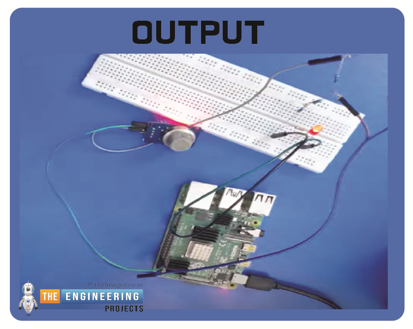
      Hello friends, I hope you all are having fun. Today, I am going to share the 9th tutorial of Section-III in our Raspberry Pi 4 Programming Course. In the previous tutorial, we interfaced an air pressure sensor BMP180 with Raspberry Pi 4. In this tutorial, you'll learn how to interface an MQ-2 gas sensor with a Raspberry Pi 4.

      Many apartments, residences, and workplaces rely heavily on these gas sensors to detect smoke or gas and alert the appropriate personnel in an emergency. In addition to gas and smoke, this sensor is sensitive to various odorous gases.

      Project Description

      Today, we will interface a gas sensor MQ-2 with Raspberry Pi 4 and will display the values on Raspberry Pi Console Window.

      Components Required

      These are the components used in today's project:

      • Raspberry Pi 4
      • MQ-2 Smoke Sensor
      • MCP3002 ADC

      MQ-2 Gas Sensor Pinout

      • MQ-2 is a low-cost electronic sensor, used to sense the intensity of gases in the surrounding.
      • MQ-x(MQ-1 to MQ-9) is a family of gas sensors used to detect different kinds of gases in the environment i.e. methane, propane, hydrogen etc.
      • The MQ-2 gas sensor is used in security systems to detect potentially dangerous gases or flammable smoke.
      • MQ-x sensors are inexpensive, simple-to-operate with an extended sensing range that may be narrowed to control the level of sensitivity.

      • The MQ-2 Gas sensor contains four inputs, two of which are reserved for Vcc and GND, and the remaining two can concurrently output digital and analog data.
      • The image above reveals that the module incorporates two onboard LEDs. When power is provided to the board, the power LED lights up, while the Dout LED lights up when the potentiometer's trigger value is achieved.
      • When an analog signal is received from the gas sensor, the board's integrated comparator OP-Amp converts it to a digital one.
      • In addition, the device's sensitivity can also be fine-tuned using the included Trim-pot.

      Now let's have a look at the Mq-2 Pinout:

      MQ-2 Pinout

      Here's the pinout diagram of MQ-2 sensor:

      • Vcc: The VCC pin on the Gas Sensor is its power input and is connected to 5V.
      • GND: The board's ground, denoted by the symbol GND, must be linked to the ground pin.
      • Dout: Pin Dout is the board's digital output; a low reading indicates the absence of gas or smoke, while a high reading indicates its presence.
      • Aout: The board's Analog output pin will provide an analog signal between the Vcc input and ground, denoted by the symbol "Aout", depending on the measured gas intensity.

      How does the gas sensor function?

      To correctly identify combustible glasses, the MQ-2 gas sensor employs a heating element; however, having such a component close to combustible gases would be catastrophic, so the sensor is built with anti-explosion protection consisting of two thin lines of stainless steel mesh, as can be seen in the image below. In this case, the stainless steel mesh houses the heating element.

      Its mesh structure not only blocks out solids like dust and dirt but also keeps out particles in the air that are too big to be gaseous, such as oxygen and nitrogen. In this case, decapitating the sensor reveals that it consists of two main parts. The nichrome wire that does the heating is accompanied by a platinum wire that has been coated with tin dioxide for the sensing part. We have already removed the protective cap to prevent you from accidentally slicing your sensor, as shown in the figure below.

      After the mesh is taken off, the sensor reveals its proper form. Stainless steel mesh was cut and attached to the sensor's housing, as shown in the top image. The sensory component that we have been discussing is now readily apparent. Since the actual detecting and heating element is attached to the sensor's six legs in a star configuration, the sensor's pins also take on that shape. Bakelite, used to increase the sensor's heat conductivity, is visible at the base of the device (black).

      Module MQ-2 Gas Sensor Internal Design

      Here is a pictorial representation of the circuitry inside the MQ-2 gas sensor module. This module's schematic is quite elementary, and its construction requires only a few essential parts. The following schematic could be helpful if you need to construct this circuit quickly:

      The LM393 op-amp is shown in the diagram; it is a +5V-powered, low-power op-amp with a small offset voltage. The MQ-2 sensor requires at least 5V, so 3.3V can't be used to power the circuit. This op-amp is primarily responsible for performing the digital-to-analog conversion of analog input signals. In addition, the MQ-2 Sensor module's sensitivity and triggering voltage can be fine-tuned via an onboard 10K potentiometer. In addition, there are two LED lights. As soon as power is supplied to the board, the power LED lights up, while the trigger LED lights up when a predetermined threshold is met. A pair of decoupling capacitors helps keep the board quiet.

      MQ-2 gas sensor preheating time:

      It would be best if you let the gas sensor stabilize after being preheated before you can use it. Moreover, a 24-hour preheat period is specified on the device's datasheet. Does this indicate that it must be on for 24hrs before being used?

      The resounding "NO" is the clear response to this inquiry. This only denotes that a continuous 24-hour run is required to acquire the typical performance figures in the datasheet. And after 24 hours in their lab, they measured it. To stay within tolerance, you must adhere to the specified preheating time of 24 hours. Considering the small space, the sensor should reach temperature equilibrium in under 30 minutes. Nevertheless, you may get results within a few percentage points of the datasheets in minutes.

      Suppose you need a precise reading of the gas concentration. In that case, you should preheat your sensor for 24 hours, ensure it is properly calibrated, and find a way to account for ambient variables such as temperature and humidity.

      With the MQ-2 Gas sensor, you can do more than detect the presence of butane and hydrogen gas; you can also measure the concentration of these gases in parts per million. Detecting the gas and determining its concentration in parts per million are two very different processes. Detecting a gas's level and subsequent increase in concentration is the primary subject of this essay. In addition, we will briefly touch on precisely calculating the gas concentration in parts per million, for which a different method is required.

      Liquefied Petroleum Gas, Butane, and Hydrogen Detection Using the MQ-2

      A can of LPG gas is shown above; when the gas is sprayed, the surrounding concentration of gas increases; repeating the process results in even higher gas concentrations. The multimeter will show an increase in the sensor's voltage reading as the gas concentration rises. Also, the module's green LED will illuminate when it hits the user-defined threshold.

      Raspberry Pi MQ-2 Detector Circuit Diagram

      The smoke sensor is powered by connecting pin 2 to the 5V connector and pin three to the GND terminal on pi 4. This provides the 5 volts that are required to power the smoke detector.

      Our application will be set up to turn on the light when the smoke detector's voltage rises above a user-defined threshold.

      Now that we've established the physical links, all that's missing is the software we've been developing.

      Complete code

      import RPi.GPIO as GPIO

      import time

      GPIO.setmode(GPIO.BCM)

      GPIO.setwarnings(False)

      GPIO.setup(14,GPIO.IN)

      GPIO.setup(12,GPIO.OUT)

      GPIO.output(12,False)

      while True:

          button_state=GPIO.input(12)

          if button_state == False:

              GPIO.output(12,True)

              while GPIO.input(14) == False:

                  time.sleep(0.2)

          else:

              GPIO.output(12,False)

      Output

      Conclusion

      Follow the steps in this tutorial. You should be able to connect the MQ-2 sensor to a breadboard and a Raspberry Pi, turn on the SPI interface, and then read sensor values using the most recent Circuit Python library. You can accomplish the same thing for additional MQ-x sensors by modifying the file depending on the sensor's design and then connecting each sensor to a separate MCP3008 channel to read its values simultaneously. The following tutorial will teach you how to use a Raspberry Pi 4 with BLE to manage your household gadgets.

      Interface a 4-Channel Relay with Raspberry Pi 4

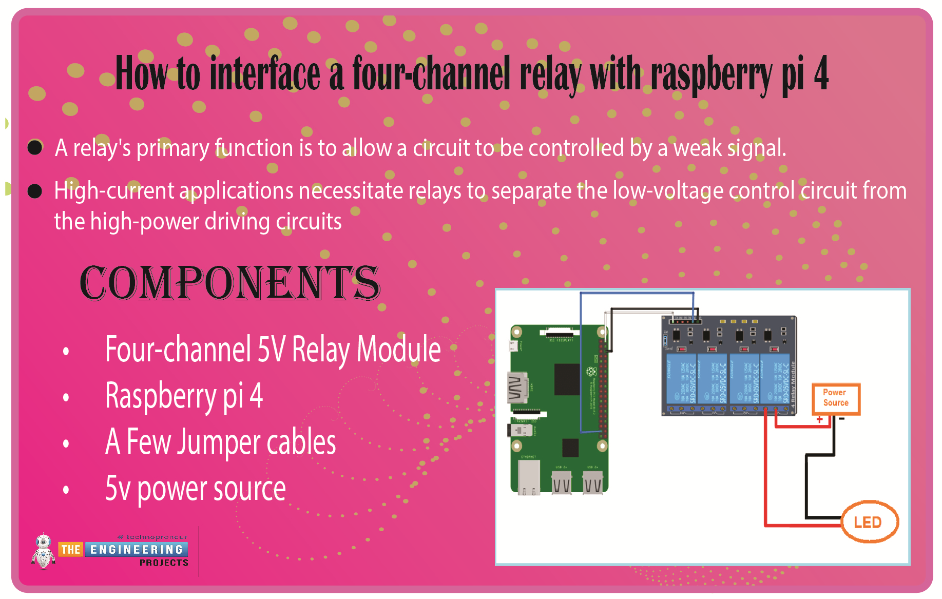
      We learned in the previous tutorial how to connect a joystick to a Raspberry Pi 4 using an mcp3008 and an op-amp IC, the LM324A. For each of the interface methods we studied, we created a python script allowing us to interact with the circuit. This tutorial will show you how to connect a 4-channel relay module with a Raspberry Pi to carry out switching.

      A relay's primary function is to allow a circuit to be controlled by a weak signal. High-current applications necessitate relays to separate the low-voltage control circuit from the high-power driving circuits. Because of this, understanding it is crucial for those interested in industrial or household automation.

      If you've been tinkering with a raspberry pi for a while, consider the various ways in which you might put it to use.

      So let’s dive in!

      Components

      • Four-channel 5V Relay Module

      • Raspberry pi 4 

      • A Few Jumper cables 

      • 5v power source

      The raspberry pi has real-world uses, such as remotely turning a device on or off over the internet, sensors, or a mobile app communicating with the pi via Bluetooth. If we can master this, we will open up a world of possibilities.

      Raspberry Pi as a Device Switch

      Anybody who has experimented with a Raspberry Pi knows it has a GPIO.

      The 40-pin general-purpose input/output (GPIO) connector is great for connecting various output devices. Since it is a digital computer, Raspberry Pi's GPIO pins can provide logic outputs. Logic 0 and 1 are the terms used to describe these two possible results from a logic circuit. If you write a program to make a Raspberry Pi pin write logic zero, you'll get a real-world GND potential. Likewise, when logic 1 is written on the Raspberry Pi pin, +3.3V is produced.

      Logic 0 (gnd) and logic 1 (+3.3v) may be generated on any Raspberry Pi output pin with some programming. However, the output voltage is too low to power any real-world equipment. A maximum of 20 mA can be drawn from the output pin, as the 3.3V generated is currently limited. This only means that we can connect an LED straight to a Raspberry Pi gpio pin. In addition to the DC motor, no other output device can be connected directly to the raspberry pi's pin. Because of this, a different method is required when connecting an AC device.

      How do relays work?

      This image is a cross-sectional diagram of a relay's inner workings. A control coil encloses a core made of iron. When power is supplied to the control coil, an electromagnet begins to energize, boosting the strength of the magnetic field it produces. As a result, the top contact arm attracts the lower fixed arm, closing the contacts and completing the circuit. However, if the relay were de-energized before the connections were closed, the contacts would travel the opposite way, creating an open circuit. When the coil current is shut off, the spring will return the movable armature to its original position.

      The operation of a relay is identical to that of a switch. This also means that the same principle applies. When a relay is used, one or even more poles are flipped. Each pole has two primary contact directions. They have NO contact, commonly known as the Normal Open Contact configuration. Connecting with someone is another name for this action. On activation, the relay completes the circuit. Once the relay is deactivated, the circuit is broken.

      NC contact is short for normally closed contact. This is synonymous with the term "break contact." In contrast to "NO contact," communication will occur. By switching on the relay, the circuit is broken. As soon as the relay is turned off, the circuit is complete.

      A relay's COM contact is shared by the normally closed (NC) and normally open (NO) contacts.

      An example of a relay module with two channels is displayed here. As its name implies, a two-channel relay module consists of a circuit with two independent relays built in. This enables the simultaneous manipulation of two distinct gadgets. It follows that the greater the available channels, the more gadgets we can link together.

      Let's connect the Pi 4 to the 2-channel relay now. With its four corresponding pins, the 2-channel relay may communicate with a Raspberry Pi. VCC, GND, IN1, and IN2 are the inputs. Current input higher than 30 mA and an input voltage of 5 V is required to power the relay module. As a result of this glaring current shortfall, we must rely on an external power source. Here, we'll employ the widely used MB102 Breadboard Power Supply, an external power supply board. If you're curious about this power source and why we decided to use it, there are some helpful links below. A 3.3 V Relay is what you'll need to operate with Relays without an external power supply.

      The relay module's VCC pin must be connected to the power supply's 5 V pin. Then Join the Raspberry Pi 4's ground pin (GND) to the power supply's ground pin (GND). The next step is to attach a jumper wire between the power supply's second GND port and the Raspberry Pi's second GND port. As a result, the ground pin on the Pi 4, the relay switch, and the power source are now all connected. Last but not least, connect a push button to GPIO 2 to activate the relay. Let's connect a few high-powered gadgets across the relay's output now. As seen in the circuit schematic, a CFL is connected to the NC and COM ports.

      Using a Relay as a Switching Circuit

      As was previously mentioned, the RPi is a computer with an output range of only +3.3v to 0v. We need a dedicated electronic switching circuit to link any real-world device to the Raspberry Pi and enable it to switch. Assume throughout this lesson that you want to control an electrical lamp using raspberry pi. A switching circuit is required because we cannot wire the light bulb directly to the raspberry pi. There must be a switching circuit, such as a relay, to turn on and off AC appliances.

      The following graphic depicts the internal structure of a relay.

      Above, you can see that a basic relay has five connections. The electromagnetic coil's two ends, L1 and L2, serve as the magnet within the relay. Directly connecting the L1 Or L2 to a DC power supply is possible. The coil becomes an electromagnet when it is supplied with an electric current. Unlike the usually closed (NC) and ordinarily open (NO) terminals, the Common terminal can be moved.

      Working of Relays

      The NC terminal serves as the home of the common terminal, which is held in place using sprint tension. This is the relay's initial setting. In a standard setup, the NC and COM terminals of a relay are linked when the device is positioned on a flat surface. The coil becomes magnetized whenever a voltage is placed between coil terminals L1 and L2. The spring tension is opposed by the magnetic force that pulls the common terminal off of NC and onto NO. As long as the relay is live, there will be continuity between NO and COM. Magnetization ceases when the coil voltage is removed, and the common terminal reverts to the NC Terminal, as depicted below.

      To conclude, we can switch any AC device on and off with a relay if we know how to do so effectively. However, the issue of activating the relay itself remains to be seen. Typically, relays require a voltage of 12v or 24v, which the Raspberry Pi cannot produce. A microprocessor cannot supply the 30-50mA current required for relays that operate on +5v coil voltage. Consequently, a relay switching circuit is required rather than a direct connection to the raspberry pi.

      An explanation of relay control

      By adjusting the voltage at the GPIO pins, you may toggle the state of any relay module, whether it's attached directly to the ports or via a relay HAT. Using Python in conjunction with the GPIO library is the simplest solution.

      After establishing a connection to the desired GPIO pin, changing its state is as simple as issuing a single command in Python. Pins 26, 20, and 21 on the GPIO header are used for the Waveshare HAT relays. For this reason, for instance, the first relay's power supply can be switched after a delay of just one second.

      Sample code

      import time

      import RPi.GPIO as GPIO

      relay_ch = 26

      GPIO.setwarnings(False)

      GPIO.setmode(GPIO.BCM)

      GPIO.setup(relay_ch, GPIO.OUT)

      GPIO.output(relay_ch, GPIO.LOW)

      time.sleep(1)

      GPIO.output(relay_ch, GPIO.HIGH)

      GPIO.cleanup()


      Using a signal from a microcontroller like a Raspberry Pi, we can switch a DC load with a transistorized switching circuit. Just below, you'll find a quick breakdown of how transistors function.

      Here is the complete circuit for using a transistor to switch a relay using a Raspberry Pi.

      As demonstrated in the diagram above, the transistor controls the switching of the relay coil, while the relay terminals control the AC load. Any AC load can be connected to a Raspberry Pi using the circuit above and turned on or off remotely.

      This setup makes use of the following Components:

      • Q1 = It can be any regular NPN transistor; we chose a BC548.

      • R1 = The resistor has a 330-ohm value.

      • D1 = inexpensive switching diodes such as 4148

      • RL1 = 12v Relay

      Diode D1 is a protection device that allows the relay to be easily turned off, as shown in the diagram.

      The transistor base resistor will receive the signal from the raspberry pi pin. Here's a program that will turn on a relay when the output is set to HIGH and turn it off when the output is set to LOW.

      Sample code

      led1 = 21 #GPIO pin to connect to relay

      import RPi.GPIO as GPIO

      import time

      GPIO.setmode(GPIO.BCM)

      GPIO.setup(led1, GPIO.OUT)

      while True:

          GPIO.output(led1, True)    

          time.sleep(2)

          GPIO.output(led1, False)

          time.sleep(2)

      The function of transistors in a relay module.

      A transistor can open and close an electronic gate millions of times per second, allowing electrical signals to pass through and out. As long as electricity flows, the circuit is active; otherwise, it is cut off. Modern telecommunications systems are built on complicated switching circuits that rely on transistors. Circuits can also flip at extremely fast rates, with some offering switching speeds of over 100 billion on/off cycles per second or hundreds of gigahertz.

      A logic gate, constructed from several transistors, compares input currents and generates a unique result. Logic gates allow computers to use Boolean algebra to make straightforward decisions. Modern computers and software applications are built on these methods.

      Four-channel relay module

      A relay module can be easily controlled by connecting its signal pin to the GPIO on a Raspberry Pi and then applying the rated input voltage from the power supply. The necessary transistors and switching circuitry are already on this board. All you have to do to use such a relay module is connect the GND of the power source that powers the relay module (5v/12v/24v) to the GND of the raspberry pi. 

      Python code for a 4-channel relay

      import RPi.GPIO as GPIO

      import time

      Relay_Ch1 = 26

      Relay_Ch2 = 20

      Relay_Ch3 = 21

      GPIO.setwarnings(False)

      GPIO.setmode(GPIO.BCM)

      GPIO.setup(Relay_Ch1,GPIO.OUT)

      GPIO.setup(Relay_Ch2,GPIO.OUT)

      GPIO.setup(Relay_Ch3,GPIO.OUT)

      print("Setup The Relay Module is [success]")

      try:

      while True:

      #Control the Channel 1

      GPIO.output(Relay_Ch1,GPIO.LOW)

      print("Channel 1:The Common Contact is access to the Normal Open Contact!")

      time.sleep(0.5)

      GPIO.output(Relay_Ch1,GPIO.HIGH)

      print("Channel 1:The Common Contact is access to the Normal Closed Contact!\n")

      time.sleep(0.5)

      #Control the Channel 2

      GPIO.output(Relay_Ch2,GPIO.LOW)

      print("Channel 2:The Common Contact is access to the Normal Open Contact!")

      time.sleep(0.5)

      GPIO.output(Relay_Ch2,GPIO.HIGH)

      print("Channel 2:The Common Contact is access to the Normal Closed Contact!\n")

      time.sleep(0.5)

      #Control the Channel 3

      GPIO.output(Relay_Ch3,GPIO.LOW)

      print("Channel 3:The Common Contact is access to the Normal Open Contact!")

      time.sleep(0.5)

      GPIO.output(Relay_Ch3,GPIO.HIGH)

      print("Channel 3:The Common Contact is access to the Normal Closed Contact!\n")

      time.sleep(0.5)

      except:

      print("except")

      GPIO.cleanup()

      Though I only connected to a single module, adding three more lights to the 4-channel relay board is as simple as looping the live wire from module to module and sharing a common ground, as illustrated in the diagram below.

      At this point, the raspberry pi 4 controls the 4-channel relay module. Closed-loop control for high-powered equipment is made possible by incorporating such code in considerably more complex scripts that consider human input or sensor readings.

      Output

      Conclusion

      Due to human fallibility, it is necessary to install home automation systems to ensure electricity is used efficiently and safely wherever possible. As an intelligent platform, Raspberry Pi enables the interconnection and remote control of many home appliances over a single network infrastructure—specifically, the internet. Because of the convenience provided by these appliances.

      Home automation systems are a promising new trend in appliance manufacturing to reduce energy use and human error. Raspberry pi-based automation is cutting-edge and innovative. Automating tasks is easier with a Raspberry Pi.

      Tell me if you had trouble understanding it or connecting your relay module to your Raspberry Pi 4 in the comments. The next tutorial will teach you how to connect a GPS module to a Raspberry Pi 4.

      Interface Joystick with Raspberry Pi 4 using MCP3008 & LM324

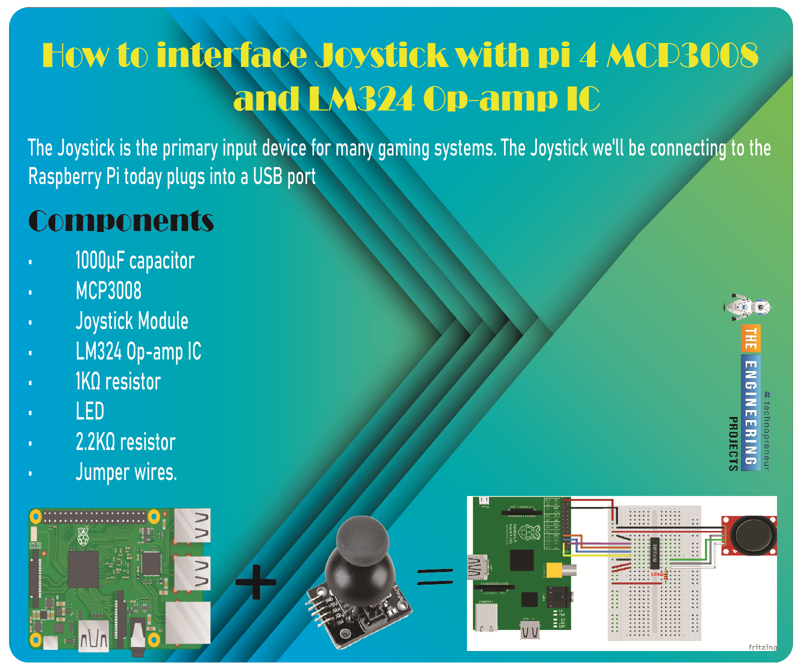
      Greetings, and welcome to the next tutorial in our series on programming for the Raspberry Pi 4. The previous tutorial showed us how to connect a 4x4 keypad to a Raspberry Pi 4. In the previous tutorial, we examined the inner workings of the 4-by-4 keyboard; in this one, we'll use the MCP3008 and the LM324 Op-amp IC to connect a joystick to the Raspberry Pi 4. The Joystick is the primary input device for many gaming systems. The Joystick we'll be connecting to the Raspberry Pi today plugs into a USB port, but there are plenty of situations when having access to the Pi's GPIO pins would be useful. We'll review the steps for preparing the circuit for each interface technique and creating a corresponding python script.

      So let’s dive in!

      Components

      The hardware utilized in this instance is a Pi 4 running Raspbian. All the prerequisites for hardware and software have already been covered, and you can find them in the Raspberry Pi Introduction; other than that, we need:

      • 1000µF capacitor

      • MCP3008

      • Joystick Module

      • LM324 Op-amp IC

      • 1KΩ resistor 

      • LED

      • 2.2KΩ resistor 

      • Jumper wires.

      Connecting an MCP3008 to a Raspberry Pi joystick

      There is a wide variety of joysticks to choose from. In the diagram below, we see a common Joystick module. The Analog Outputs generated by this Joystick module often fluctuate in response to the orientation of the Joystick. Furthermore, we can determine the movement's direction by analyzing these voltage fluctuations with a microcontroller.

      Joystick


      In my setup, pressing down on the Joystick toggles an on/off state for the button, so you may use any standard GPIO pin to connect yours. I'll connect it in the same way as the potentiometers, though.

      You'll need to familiarize yourself with the Serial Peripheral Interface bus protocol and understand how to configure it on the Pi before connecting the analog controllers to the Pi with a little chip that employs SPI as a communication medium. You can find excellent guides on accomplishing this on the Pi 4 Spy website.

      The SPI bus will be activated on specific GPIO pins, which will be the first thing you learn. In my experience, Method 1 (opening a config panel in Raspbian and choosing the SPI option) worked flawlessly. Then, you'll need to ensure the MCP3008 chip is wired properly. That will serve as the connection between your Joystick and the Pi. Pulse-width modulation is worth investigating if you want to change your RGB LED (PWM) colours.

      Circuit diagram

      In case you get stuck, I've included some screenshots and a layout of my setup below.

      Input reading

      Upon enabling SPI, you should have double-checked that pi-spyder was installed. That is required so that the analog device's input may be read. Setting the LED's colour to correspond with the Joystick's location on the RGB colour wheel may be fun. Let's pretend the X-axis is horizontal over Yellow and the Y-axis is vertical over Orange.

      Code

      import math

      import RPi.GPIO as GPIO

      import spidev

      # Open SPI bus

      spi = spidev.SpiDev()

      spi.open(0, 0)

      # Define sensor channels (3 to 7 are unused)

      mcp3008_switch_channel = 0

      mcp3008_x_voltage_channel = 1

      mcp3008_y_voltage_channel = 2

      # Define RGB channels

      red_led = 36

      green_led = 31

      blue_led = 37

      def read_spi_data_channel(channel):

          adc = spi.xfer2([1, (8+channel) << 4, 0])

          return ((adc[1] & 3) << 8) + adc[2]

      def convert_coordinates_to_angle(x, y, center_x_pos, center_y_pos):

          dx = x - center_x_pos

          dy = y - center_y_pos

          rads = math.atan2(-dy, dx)

          rads %= 2 * math.pi

          return math.degrees(rads)  

      def adjust_angle_for_perspective_of_current_led(angle, led):

          led_peak_angle = 90 if led == 'R' else (210 if led == 'B' else 330)

          return ((angle - led_peak_angle) + 360) % 360

      def calculate_next_pwm_duty_cycle_for_led(angle, led):

          angle = adjust_angle_for_perspective_of_current_led(angle, led)

          if 120 < angle < 240:

              return 0

          elif angle <= 120:

              return 100 - (angle * (100 / 120.0))

          else:

              return 100 - ((360 - angle) * (100 / 120.0))

      def is_joystick_near_center(x, y, center_x_pos, center_y_pos):

          dx = math.fabs(x - center_x_pos)

          dy = math.fabs(y - center_y_pos)

          return dx < 20 and dy < 20

      def main():

          # Center positions when Joystick is at rest

          center_x_pos = 530

          center_y_pos = 504

          GPIO.setmode(GPIO.BOARD)

          GPIO.setup([red_led, green_led, blue_led], GPIO.OUT, initial=GPIO.LOW)

          pwm_r = GPIO.PWM(red_led, 300)

          pwm_g = GPIO.PWM(green_led, 300)

          pwm_b = GPIO.PWM(blue_led, 300)

          pwm_instances = [pwm_r, pwm_g, pwm_b]

          for p in pwm_instances:

              p.start(0)

          try:

              while True:

                  # If the joystick switch is pressed down, turn off the LEDs

                  switch = read_spi_data_channel(mcp3008_switch_channel)

                  if switch == 0:

                      for p in pwm_instances:

                          p.ChangeDutyCycle(0)

                      continue

                  # Read the joystick position data

                  x_pos = read_spi_data_channel(mcp3008_x_voltage_channel)

                  y_pos = read_spi_data_channel(mcp3008_y_voltage_channel)

                  # If Joystick is at rest in the center, turn on all LEDs at max

                  if is_joystick_near_center(x_pos, y_pos, center_x_pos, center_y_pos):

                      for p in pwm_instances:

                          p.ChangeDutyCycle(100)

                      continue

                  # Adjust the duty cycle of LEDs based on the joystick position

                  angle = convert_coordinates_to_angle(x_pos, y_pos, center_x_pos, center_y_pos)

                  pwm_r.ChangeDutyCycle(calculate_next_pwm_duty_cycle_for_led(angle, 'R'))

                  pwm_g.ChangeDutyCycle(calculate_next_pwm_duty_cycle_for_led(angle, 'G'))

                  pwm_b.ChangeDutyCycle(calculate_next_pwm_duty_cycle_for_led(angle, 'B'))

                  # print("Position : ({},{})  --  Angle : {}".format(x_pos, y_pos, round(angle, 2)))

          except KeyboardInterrupt:

              pass

          finally:

              for p in pwm_instances:

                  p.stop()

              spi.close()

              GPIO.cleanup()

      if __name__ == '__main__':

          main()

      So that these methods' input, output, and goals are as apparent as possible, I've put in more effort than normal to comment on the code.

      Output

      Using OP-amp IC to interface the Joystick to pi 4

      Both the X and Y axes are in use. A potentiometer, or "pot," is attached to each axis of the JOY STICK. Rx and Ry are the resulting midpoints of these pots. It follows that Ry and Rx are the movable centers of these kettles. While the Joystick is idle, Rx and Ry serve as voltage dividers.

      The voltage at the Rx pin shifts as the Joystick is pushed along the horizontal axis. Similarly, the value at the Ry pin shifts as the device is tilted or turned vertically. The Joystick can be moved in four directions, with two ADC outputs. The voltage at each pin increases or decreases in response to the stick's orientation changes.

      As is well-known, Raspberry Pi lacks any built-in Analog Digital Converter hardware. The Pi would be unable to recognize this module if it were attached directly. We shall employ comparators based on operational amplifiers to verify the voltage outputs. These OP-Amps send signals to the Raspberry Pi, and the Pi uses those signals to turn on and off the LEDs. Here, we've implemented a set of four LEDs to represent the four possible Joystick orientations. Please view the accompanying demonstration video.

      All 17 GPIO pins have a maximum voltage rating of +3.3V, meaning that any outputs from the Op-amps must be less than that. We needed an op-amp that could operate at 3V, and the LM324 met both requirements. This IC's pins are a good match for the Raspberry Pi's GPIO connectors.

      An explanation of operational amplifier circuits.

      It has been said that operational amplifiers are the "workhorse" of analog circuits. The LM358 and the LM741 are widely utilized as the most popular varieties of Op-Amp IC. Many functions, such as an amplifier, integrators, differentiators, summers, voltage followers, and more, can be achieved with a single operational amplifier (Op-Amp) by altering the circuitry. Below is a list compiled by Circuit Digest of many Op-amp Circuits, each of which includes a tidy circuit diagram and a practical DIY hardware description to help you learn all about operational amplifiers.

      General Operating Conditions of an Operating Amplifier

      • When utilized in Open-loop mode, the Operational Amplifier (or "Op-amp" for short) can be a perfect amplifier with a typical DC gain of over 100,000 or 100dB.

      • In its most fundamental form, an operational amplifier (Op-amp) is a three-terminal device with two inputs and a single output (excluding power connections).

      • The power supply for an operational amplifier can be either a single DC voltage or a pair of supplies, one positive (+V) and one negative (-V).

      • There can be "no current that flows through either of its two inputs" because of the operational amplifier's zero input offset voltage, V1 = V2, and its infinite input impedance, Z = infinity.

      • Also, the output impedance of an operational amplifier is zero (Z = 0).

      • Differential amplifiers, or op-amps, are voltage-sensing amplifiers that magnify the voltage difference between their input terminals by a fixed factor called Gain ( A ).

      • Sometimes called "Open-loop Gain," (A) is a common measure of an amplifier's effectiveness.

      • This open-loop gain can be considerably reduced and controlled by connecting the op-output amp to one of its input terminals to close the loop.

      • There are two common ways to wire operational amplifiers, known as inverting and non-inverting.

      LM324 circuit diagram

      The LM324 IC includes four OP-AMP comparators to identify Joystick's four possible inputs. Here is the LM324 IC schematic straight from the datasheet.

      The following circuit diagram shows the components that make up the Joystick module and the connections that allow it to communicate with the Raspberry Pi. All four comparators within the LM324 are denoted by the U1:A, U1:B, U1:C, and U1:D pins. In the circuit schematic, we have labelled the LM324 IC's comparator pins so that you can easily identify which one goes to which comparator.

      Working Explanation

      We have OP-AMP1 (or U1:A) and OP-AMP2 (or U1:B) for sensing Joystick motion in the Y axis, and OP-AMP3 (or U1:C) and OP-AMP4 (or U1:D) for sensing Joystick motion in the X axis.

      OP-AMP1 picks up on the Y-axis downward movement of the Joystick:

      The 2.3V (produced by a voltage divider circuit consisting of 1K and 2.2K) is attached to the negative electrode of comparator U1:A, while the positive terminal is wired to Ry. There is an increase in Ry voltage as the Joystick is moved downward along its Y axis. If the input voltage exceeds 2.3V, the OP-AMP will output +3.3V at the output Pin. In response to the OP-HIGH AMP's logic output, the Raspberry Pi will turn on and off an LED.

      Joystick up, Y-axis, is detected by OP-AMP2:

      The 1.0V (supplied by a voltage divider circuit consisting of 2.2K and 1K) is connected to the comparator U1: negative B's terminal, while the positive terminal is wired to Ry. As you raise the Joystick's Y axis, the voltage on Ry will drop. The OP-AMP output will go Low when this voltage falls below 1.0V. When the Raspberry Pi sees the LOW logic output from the OP-AMP, it will respond by turning on and off an LED.

      With OP-AMP3, X-axis joystick motion to the left is detected:

      The comparator U1: negative C's terminal is given 2.3V (1K and 2.2K via a voltage divider circuit), while the positive terminal is linked to Rx. Increasing Rx voltage occurs when the Joystick is moved to the left along its x-axis. If the input voltage exceeds 2.3V, the OP-AMP will output +3.3V at the output Pin. In response to the OP-HIGH AMP's logic output, the Raspberry Pi will turn on and off an LED.

      OP-AMP4 recognizes an X-axis joystick movement to the right:

      U1:4's negative terminal is given 1.0V (through a voltage divider circuit of 2.2K and 1K), while the positive terminal is linked to Rx. Rx voltage drops as the Joystick is moved to the right along its x-axis. The OP-AMP output will go Low when this voltage falls below 1.0V. When the Raspberry Pi sees the LOW logic output from the OP-AMP, it will respond by turning on and off an LED.

      This allows Raspberry Pi to receive input from all four logic that controls the Joystick's four directions. Raspberry Pi uses inputs from these comparators to control the state of the LEDs. Here are the terminal outputs from our Raspberry Pi program, which also prints the Joystick's orientation to the screen.

      A Python script is available below. The code is simple, and the comments make it easy to understand.

      Complete code

      import RPi.GPIO as IO    # calling for the header file, which helps in using GPIOs of PI

      import time              # we are calling for time to provide delays in the program

      IO.setwarnings(False)    # do not show any warnings

      IO.setmode (IO.BCM)      #programming the GPIO by BCM PINs (like PIN29 as GPIO5)

      IO.setup(21,IO.OUT)      # initialize GPIO21 as an output      

      IO.setup(20,IO.OUT)

      IO.setup(16,IO.OUT)

      IO.setup(12,IO.OUT)

      IO.setup(27,IO.IN)      # initialize GPIO27 as an input

      IO.setup(4,IO.IN)

      IO.setup(22,IO.IN)

      IO.setup(17,IO.IN)

      while 1:

          if (IO.input(27) == 0):  #If GPIO 27 goes low toggle LED on 21pin and print RIGHT

              IO.output(21,1)

              time.sleep(0.01)

              IO.output(21,0)

              print ("RIGHT")

          if (IO.input(4) == 1):   #If GPIO 4 goes high toggle LED on 20pin and print LEFT

              IO.output(20,1)

              time.sleep(0.01)

              IO.output(20,0)

              print ("LEFT")

          if (IO.input(22) == 0):  #If GPIO 22 goes low toggle LED on 16pin and print UP

              IO.output(16,1)

              time.sleep(0.01)

              IO.output(16,0)

              print ("UP")

          if (IO.input(17) == 1):  #If GPIO 17 goes high toggle LED on 12pin and print DOW

              IO.output(12,1)

              time.sleep(0.01)

              IO.output(12,0)

              print ("DOWN")           

      Output

      Conclusion

      As we've seen in this guide, the Pi 4 computer lacks an analog input. The only data it can process is digital. Contrast it with the plentiful analog inputs of common microcontrollers like Arduino, AVR, or PIC. Many sensors produce analog outputs; therefore, we need a method to make the Pi analog-friendly. To that end, we have considered two alternatives. Connecting an MCP3008 microcontroller and an LM324 operational amplifier integrated circuit creates a "bridge" between analog and digital signals. If you have any questions regarding the setup or the code, or if you run into any problems, please let me know in the comments, and I'll do my best to help. The next article will teach you how to use a Raspberry Pi 4 to operate a relay board with four independent outputs.

      Interface Weight Sensor HX711 with Raspberry Pi 4

      Welcome to the next tutorial of our raspberry pi programming tutorial. The previous tutorial showed us how to set up a weather station using the Internet of Things (IoT) on a Raspberry Pi 4. First, we studied how a weather station works on a fundamental level. Then we developed a Python script to collect data from the station. In contrast, we'll construct an automatic gate using a Raspberry Pi, a load cell, and an HX711 weight sensor.

      These pressure-sensitive gates are common in shopping centers and showrooms; they open when someone is in the immediate vicinity and close again when the person is out of sight. Like the Automatic Gate, we just made, this one will open in response to weight or pressure and stay that way until the force is removed. If you remove the load from this gate, it will close independently.

      In this example, a DC motor is the gate, and a piece of rigid cardboard is the load-bearing surface.

      Components

      • Raspberry Pi 4

      • DC motor

      • electric gate or DVD trolley

      • 16x2 LCD

      • Power supply or power bank

      • HX711 Load Cell Amplifier Module 

      • L293D Motor Driver IC

      • Jumper wires

      • Breadboard

      Load cell, HX711 Weight Sensor Module, and Nut Bolts

      A load cell transducer converts mechanical input (force or pressure) into an electric signal. For example, many strain gauges are fastened to an elastic element (with a highly repeatable deflection waveform) to create a load cell.

      The load cell depicted in the figure above features four strain gauges, two on each top and bottom surface.

      The elastic element of the resistive load cell illustrated above deflects under the applied force, causing a strain at the stress points. For example, see how the animation below depicts how two strain gauges are under tension while the other two are under compression.

      The load cell's metal spring element undergoes elastic deformation due to the weight being measured. Its electrical output scales linearly with the applied force. Load cells contain a strain gauge that bends under stress. Strain gauges produce an electrical signal upon deformation due to a change in their effective resistance. Four strain gauges configured as a Wheatstone bridge make up a typical load cell. While load cells can measure loads as small as 5 kilograms or as much as 100 kilograms, we utilized one that measured up to 40 kilograms.

      As the Load cell's output electrical signals are only a few millivolts, an amplifier is required; enter the HX711 Weighing Sensor. The HX711 chip inside the HX711 Weight Sensor Module is a 24 high-precision A/D converter. The HX711 features two channels for analog input, and their gain can be programmed up to 128. The HX711 Module boosts the Load cells' light electrical output. The Arduino uses that amplified, digitally transformed signal to calculate the weight.

      Four wires lead from the load cell to the HX711 Load cell Amplifier. Red, black, white, and green/blue are the colors of these four wires. Certain modules may have different wire colors than others. Please find the diagram and connecting information below:

      • RED Wire is connected to E+

      • BLACK Wire is connected to E-

      • WHITE Wire is connected to A-

      • GREEN/BLUE Wire is connected to A+

      Channel A or Channel B differential input is chosen by the input multiplexer and fed into the low-noise programmable gain amplifier (PGA). When a 5V supply is connected to the AVDD analog power supply pin, the gain of Channel A can be set to 128 or 64, yielding a full-scale differential input voltage of 20mV or 40mV, respectively. A constant gain of 32 is applied to Channel B. Since the regulator for the analog power used by the Analog-digital converter and the sensor is integrated into the chip, there is no longer any need for a separate supply regulator. The clock input can be set manually. It can come from a crystal or on-chip oscillator that doesn't need anything extra to function. The initialization of digital interfaces is made more accessible by on-chip power-on reset circuitry. The internal registers can be used immediately without any programming. The HX711's pins are used for all of its controls.

      Fixing Load Cell with Platform and Base

      To make this system function, a Load Cell must be buried beneath the door's threshold to detect the weight of someone standing nearby. But, for the sake of demonstration, we have secured the load cell beneath a sturdy piece of cardboard. This will allow us to test the gate by placing a weight on the cell. The load cell has been securely fastened to the wooden base with nuts and bolts. Several images of the setup can be seen below:

      The resistive load cell is based on the piezo-resistive concept. The sensor's resistance changes as a function of the applied force or stress. When an external voltage is introduced, the output voltage will fluctuate due to the change in resistance.

      A capacitive load cell measures the load by measuring the voltage required to cause a change in the capacitance of a system. The capacitance of a standard parallel plate capacitor scales inversely with the distance between both the plates and proportionally with the area of overlap between the plates relative to the dielectric between them.

      Circuit Explanation

      The wiring is simple for this automatic gate, and a diagram is included for reference. The GPIO pins 18, 23, 24, 25, 8, and 7 of the Raspberry Pi are connected to the RS, EN, d4, d5, and d7 pins of the 16x2 LCD. The DT and SCK pins of the HX711 Module are wired to GPIO pins 27 and 17, respectively, on the Raspberry Pi. In contrast, the DATA and SCK pins of the Motor Driver L293D are wired to GPIO pins 12 and 16, respectively. Already stated and depicted in the circuit diagram below are the load cell connections necessary to use the HX711 Module.

      Analog Inputs 

      A differential input channel connects straight to the differential signal sent by a bridge sensor. Gain settings of 128 or 64 are selectable via programming. Since the sensor output signal is typically somewhat weak, high gains are required. These improvements translate to an input differential voltage of 20mV or 40mV at full scale when a 5V supply is connected to the AVDD port. The gain of the differential input on channel B is always 32. With a 5V supply at the AVDD pin, an input voltage of 80mV is possible.

      Working Explanation

      Raspberry Pi 4 was used as the central processing unit for this project. First, the pressure near the gate is measured by a load cell, which then sends an analog voltage signal to the HX711 Load sensor Module. Next, the output from the Load cell is amplified and converted to digital form by the HX711, a 24-bit analog-to-digital converter. After that, the Raspberry Pi receives the magnified value. The HX711 output is now converted to a weight value by Raspberry Pi. The motor driver IC L293D is then used by the Raspberry Pi to control the gate based on a comparison with the reference weight. In this case, we're using a DC motor as the gate.

      We've set the threshold at 100 grams to ensure that only people weighing more than that are allowed through the gate. Once we've removed the 100 grams or the individual is no longer present, the gate will lock. The standard weighting can be adjusted to fit your needs. The state of the gate can be shown on a 16x2 LCD screen (optional). We have created Python software to automate the entire procedure; the program's source code is available for download, along with a video demonstration.

      Programming Explanation

      In this case, Python will be used for the coding. We did not use a library to connect the HX711 load sensor to the Raspberry Pi in this project. Our only guide was the HX711 datasheet and the accompanying application notes. Nonetheless, libraries are available for this purpose; by including the library, you can obtain the weight with minimal effort.

      Then, the GPIO Library was implemented, with pins for the LCD, HX711, and DC motor defined and various calculation variables being declared.

      import RPi.GPIO as gpio

      import time

      RS =18

      EN =23

      D4 =24

      D5 =25

      D6 =8

      D7 =7

      DT =27

      SCK=17

      m1=12

      m2=1

      Following that, the below code will retrieve information from the HX711 Module.

      def readCount():

        i=0

        Count=0

        gpio.setup(DT, gpio.OUT)

        gpio.output(DT,1)

        gpio.output(SCK,0)

        gpio.setup(DT, gpio.IN)

        while gpio.input(DT) == 1:

            i=0

        for i in range(24):

              gpio.output(SCK,1)

              Count=Count<<1

              gpio.output(SCK,0)

              #time.sleep(0.001)

              if gpio.input(DT) == 0: 

                  Count=Count+1      

        gpio.output(SCK,1)

        Count=Count^0x800000

        gpio.output(SCK,0)

        return Count 

      To open or shut the gate, we now compare the HX711 Module's data with a reference weight in the main function.

      while 1:

        count= readCount()

        w=0

        w=(count-sample)/106

        print w,"g"

        if w>100:  

          setCursor(0,0)

          lcdprint("Gate Opened ")

          if flag == 0:

            gpio.output(m1, 1)

            gpio.output(m2, 0)

            time.sleep(1.3)

            gpio.output(m1, 0)

            gpio.output(m2, 0)

            time.sleep(1.5)

            flag=1;

            lcdclear()

        elif w<100:

          setCursor(0,0)

          lcdprint("Gate Closed ")

          if flag==1:

            gpio.output(m1, 0)

            gpio.output(m2, 1)

            time.sleep(1.3)

            gpio.output(m1, 0)

            gpio.output(m2, 0)

            time.sleep(2)

            flag=0

        time.sleep(0.5)

      In addition, we define several LCD-specific methods, such as begin(), which initializes the display, lcdcmd(ch), which sends commands to the display, lcdwrite(ch), which prints a single character on the display, lcdclear(), which clears the display, and lcdprint(Str), which prints a string. The complete code is included below for your perusal.

      As we have shown, an Automated Gate that detects weight using a Raspberry Pi and a load cell is relatively easy to make.

      Complete Code

      import RPi.GPIO as gpio

      import time

      RS =18

      EN =23

      D4 =24

      D5 =25

      D6 =8

      D7 =7

      DT =27

      SCK=17

      m1=12

      m2=16

      HIGH=1

      LOW=0

      sample=0

      val=0

      gpio.setwarnings(False)

      gpio.setmode(gpio.BCM)

      gpio.setup(RS, gpio.OUT)

      gpio.setup(EN, gpio.OUT)

      gpio.setup(D4, gpio.OUT)

      gpio.setup(D5, gpio.OUT)

      gpio.setup(D6, gpio.OUT)

      gpio.setup(D7, gpio.OUT)

      gpio.setup(m1, gpio.OUT)

      gpio.setup(m2, gpio.OUT)

      gpio.setup(SCK, gpio.OUT)

      gpio.output(m1 , 0)

      gpio.output(m2 , 0)

      def begin():

        lcdcmd(0x33) 

        lcdcmd(0x32) 

        lcdcmd(0x06)

        lcdcmd(0x0C) 

        lcdcmd(0x28) 

        lcdcmd(0x01) 

        time.sleep(0.0005)

      def lcdcmd(ch): 

        gpio.output(RS, 0)

        gpio.output(D4, 0)

        gpio.output(D5, 0)

        gpio.output(D6, 0)

        gpio.output(D7, 0)

        if ch&0x10==0x10:

          gpio.output(D4, 1)

        if ch&0x20==0x20:

          gpio.output(D5, 1)

        if ch&0x40==0x40:

          gpio.output(D6, 1)

        if ch&0x80==0x80:

          gpio.output(D7, 1)

        gpio.output(EN, 1)

        time.sleep(0.005)

        gpio.output(EN, 0)

        # Low bits

        gpio.output(D4, 0)

        gpio.output(D5, 0)

        gpio.output(D6, 0)

        gpio.output(D7, 0)

        if ch&0x01==0x01:

          gpio.output(D4, 1)

        if ch&0x02==0x02:

          gpio.output(D5, 1)

        if ch&0x04==0x04:

          gpio.output(D6, 1)

        if ch&0x08==0x08:

          gpio.output(D7, 1)

        gpio.output(EN, 1)

        time.sleep(0.005)

        gpio.output(EN, 0)

      def lcdwrite(ch): 

        gpio.output(RS, 1)

        gpio.output(D4, 0)

        gpio.output(D5, 0)

        gpio.output(D6, 0)

        gpio.output(D7, 0)

        if ch&0x10==0x10:

          gpio.output(D4, 1)

        if ch&0x20==0x20:

          gpio.output(D5, 1)

        if ch&0x40==0x40:

          gpio.output(D6, 1)

        if ch&0x80==0x80:

          gpio.output(D7, 1)

        gpio.output(EN, 1)

        time.sleep(0.005)

        gpio.output(EN, 0)

        # Low bits

        gpio.output(D4, 0)

        gpio.output(D5, 0)

        gpio.output(D6, 0)

        gpio.output(D7, 0)

        if ch&0x01==0x01:

          gpio.output(D4, 1)

        if ch&0x02==0x02:

          gpio.output(D5, 1)

        if ch&0x04==0x04:

          gpio.output(D6, 1)

        if ch&0x08==0x08:

          gpio.output(D7, 1)

        gpio.output(EN, 1)

        time.sleep(0.005)

        gpio.output(EN, 0)

      def lcdclear():

        lcdcmd(0x01)

      def lcdprint(Str):

        l=0;

        l=len(Str)

        for i in range(l):

          lcdwrite(ord(Str[i]))

      def setCursor(x,y):

          if y == 0:

              n=128+x

          elif y == 1:

              n=192+x

          lcdcmd(n)

      def readCount():


        i=0

        Count=0

       # print Count

       # time.sleep(0.001)

        gpio.setup(DT, gpio.OUT)

        gpio.output(DT,1)

        gpio.output(SCK,0)

        gpio.setup(DT, gpio.IN)

        while gpio.input(DT) == 1:

            i=0

        for i in range(24):

              gpio.output(SCK,1)

              Count=Count<<1

              gpio.output(SCK,0)

              #time.sleep(0.001)

              if gpio.input(DT) == 0: 

                  Count=Count+1

                  #print Count

        gpio.output(SCK,1)

        Count=Count^0x800000

        #time.sleep(0.001)

        gpio.output(SCK,0)

        return Count  

      begin()

      lcdcmd(0x01)

      lcdprint(" Automatic Gate ")

      lcdcmd(0xc0)

      lcdprint("    Using RPI   ")

      time.sleep(3)

      lcdcmd(0x01)

      lcdprint("Circuit Digest")

      lcdcmd(0xc0)

      lcdprint("Welcomes You")

      time.sleep(3)

      sample= readCount()

      flag=0

      lcdclear()

      while 1:

        count= readCount()

        w=0

        w=(count-sample)/106

        print w,"g"

        if w>100:  

          setCursor(0,0)

          lcdprint("Gate Opened ")

          if flag == 0:

            gpio.output(m1, 1)

            gpio.output(m2, 0)

            time.sleep(1.3)

            gpio.output(m1, 0)

            gpio.output(m2, 0)

            time.sleep(1.5)

            flag=1;

            lcdclear()

        elif w<100:

          setCursor(0,0)

          lcdprint("Gate Closed ")

          if flag==1:

            gpio.output(m1, 0)

            gpio.output(m2, 1)

            time.sleep(1.3)

            gpio.output(m1, 0)

            gpio.output(m2, 0)

            time.sleep(2)

            flag=0

        time.sleep(0.5)

      Conclusion

      In conclusion, a weight sensor HX711 and load cell can be easily interfaced with a Raspberry Pi 4 with careful attention to wiring and software configuration. In the right hands, the Raspberry Pi's processing capability can precisely measure mass and analyze the results.

      Users must connect the load cell's wires to the HX711 Module and then link the HX711 Module to the Raspberry Pi 4's GPIO pins to interface the weight sensor HX711 and the load cell. After that, Python libraries like "pi-plates" and "HX711" can be used to calibrate and read the sensor values.

      Once the sensor is installed, the collected data is used widely, including but not limited to weighing objects, measuring food portions, and automating manufacturing procedures. The Raspberry Pi's processing power and network adapters make it simple to incorporate weight sensing into a wide variety of projects and applications.

      For makers, hobbyists, and professionals alike, the HX711 weight sensor and load cell interface with Raspberry Pi 4 provides a robust and versatile platform for measuring and analyzing weight data. The next article will show you how to use Raspberry Pi 4 to create a smart agriculture system based on the Internet of Things.

      Interface 4x4 Keypad with Raspberry Pi 4

      Hello friends, I hope you all are doing well. Welcome to the next tutorial of our Raspberry Pi 4 programming course. In the previous lecture, we interfaced LCD 16x2 with Raspberry Pi 4. Today, we will interface a keypad 4x4 to Raspberry Pi 4. In embedded projects, a keypad is used to get user input i.e. calculator, ATM keypad etc. Different types of Keypads are available i.e. 4x4, 4x3 etc.


      So, let's get started:

      Components Required

      We will need the following components in our today's project:

      • Raspberry Pi 4
      • Keypad 4x4
      • Breadboard
      • Connecting Wires

      Keypad 4x4

      • A keypad is a collection of push buttons, arranged in a matrix form.
      • Keypad 4x3 means the keypad has 4 rows and 3 columns and 12 buttons in total.
      •  A 4 by 4 keypad membrane has 8 pins in total, its first 4 pins devoted to its rows and its second 4 pins dedicated to its columns.

      • To reduce the need for pins, they are laid out in a matrix pattern, and a membrane switch is used internally.

      • The small size, low cost, and easy-to-install features make it a more affordable alternative to touchscreens.

      Any microcontroller's GPIO can be used to power a keypad; thus, there's no need for an additional power supply. A pulse must be sent from the Raspberry Pi to all four rows of the Keypad to determine which button was pressed. If the user pushes a button associated with the currently pulled high line, the column associated with that line will be pushed high.

      The pressed button can be identified by deciphering the sequence of rows and columns. When a user hits the B button in the second row of the fourth column, Pi 4 will send a pulse to the second line and then see which of the four columns was pulled high to determine which button was pressed.

      Keypad Working

      The graphic above depicts the reasoning behind how we will interpret the keys pressed on the Keypad. As indicated, the membrane switches are laid out in a matrix.

      • In a normal condition, the four columns (C1, C2, C3, and C4) remain HIGH(internally pull-up), while all the rows  (R1, R2, R3, and R4) are provided with Ground(GND) one after the other.
      • The columns are constantly monitored by the microcontroller, to check for a LOW signal.
      • If the key "1" is pressed, the column (C1) would get "shorted" to the row (R1), resulting in a "LOW" signal at C1, which will be captured by the microcontroller.
      • Following the iteration of each row, columns are set back to High.

      I hope you understood the working of the keypad. Now let's interface our Keypad with RPi4:

      Keyboard & Raspberry Pi 4 Circuit Diagram

      We don't need to provide any power pins to these keypads. Simple, connect the Keypad's eight data pins to the RPi4's GPIO pins:

      Like the image up top, I used a monochromatic color palette. The rows are denoted by the blue connections, while the orange ones show the columns.

      Keyboard & Raspberry Pi 4 Python Code

      After connecting the pins as described above, the next step is to run a test program that outputs the Keypad's button push to the Raspberry Pi 4's console.

      # GPIO setup and imports omitted

      def readLine(line, characters):

      GPIO.output(line, GPIO.HIGH)

      if(GPIO.input(C1) == 1):

               print(characters[0])

      if(GPIO.input(C2) == 1):

                   print(characters[1])

      if(GPIO.input(C3) == 1):

               print(characters[2])

      if(GPIO.input(C4) == 1):

               print(characters[3])

      GPIO.output(line, GPIO.LOW)

      try:

      while True:

               readLine(L1, ["1","2","3","A"])

               readLine(L2, ["4","5","6","B"])

               readLine(L3, ["7","8","9","C"])

               readLine(L4, ["*","0","#","D"])

               time.sleep(0.1)

      except KeyboardInterrupt:

      print("\nApplication stopped!")

      In the above code, we have a readLine command, which reads the rows one by one and checks if the button is pressed. If any button is pressed, the digit will appear in the Pi Console. The approach also requires a dictionary of button-to-symbol correspondences.

      You can think of this code as a basic demo. You can't even press and hold a button and have it register that. Each pulse it transmits on the output line will identify a new keystroke.

      Example 2

      Below is a program that can accurately identify individual key presses and use them to activate a basic code lock.

      Complete code

      import RPi.GPIO as GPIO

      import time

      L1 = 5

      L2 = 6

      L3 = 13

      L4 = 19

      C1 = 12

      C2 = 16

      C3 = 20

      C4 = 21

      keypadPressed = -1

      secretCode = "4789"

      input = ""

      GPIO.setwarnings(False)

      GPIO.setmode(GPIO.BCM)

      GPIO.setup(L1, GPIO.OUT)

      GPIO.setup(L2, GPIO.OUT)

      GPIO.setup(L3, GPIO.OUT)

      GPIO.setup(L4, GPIO.OUT)

      GPIO.setup(C1, GPIO.IN, pull_up_down=GPIO.PUD_DOWN)

      GPIO.setup(C2, GPIO.IN, pull_up_down=GPIO.PUD_DOWN)

      GPIO.setup(C3, GPIO.IN, pull_up_down=GPIO.PUD_DOWN)

      GPIO.setup(C4, GPIO.IN, pull_up_down=GPIO.PUD_DOWN)

      def keypadCallback(channel):

          global keypadPressed

          if keypadPressed == -1:

              keypadPressed = channel

      GPIO.add_event_detect(C1, GPIO.RISING, callback=keypadCallback)

      GPIO.add_event_detect(C2, GPIO.RISING, callback=keypadCallback)

      GPIO.add_event_detect(C3, GPIO.RISING, callback=keypadCallback)

      GPIO.add_event_detect(C4, GPIO.RISING, callback=keypadCallback)

      def setAllLines(state):

          GPIO.output(L1, state)

          GPIO.output(L2, state)

          GPIO.output(L3, state)

          GPIO.output(L4, state)

      def checkSpecialKeys():

          global input

          pressed = False

          GPIO.output(L3, GPIO.HIGH)

          if (GPIO.input(C4) == 1):

              print("Input reset!");

              pressed = True

          GPIO.output(L3, GPIO.LOW)

          GPIO.output(L1, GPIO.HIGH)

          if (not pressed and GPIO.input(C4) == 1):

              if input == secretCode:

                  print("Code correct!")

                  # TODO: Unlock a door, turn a light on, etc.

              else:

                  print("Incorrect code!")

              pressed = True

          GPIO.output(L3, GPIO.LOW)

          if pressed:

              input = ""

          return pressed

      def readLine(line, characters):

          global input

          # We have to send a pulse on each line to

          # detect button presses

          GPIO.output(line, GPIO.HIGH)

          if(GPIO.input(C1) == 1):

              input = input + characters[0]

          if(GPIO.input(C2) == 1):

              input = input + characters[1]

          if(GPIO.input(C3) == 1):

              input = input + characters[2]

          if(GPIO.input(C4) == 1):

              input = input + characters[3]

          GPIO.output(line, GPIO.LOW)

      try:

          while True:

              if keypadPressed != -1:

                  setAllLines(GPIO.HIGH)

                  if GPIO.input(keypadPressed) == 0:

                      keypadPressed = -1

                  else:

                      time.sleep(0.1)

              else:

                  if not checkSpecialKeys():

                      readLine(L1, ["1","2","3","A"])

                      readLine(L2, ["4","5","6","B"])

                      readLine(L3, ["7","8","9","C"])

                      readLine(L4, ["*","0","#","D"])

                      time.sleep(0.1)

                  else:

                      time.sleep(0.1)

      except KeyboardInterrupt:

          print("\nApplication stopped!")

      Programming using interrupt

      You may have noticed that the "while" loop we used above is polling for each row of our Keypad. This is OK for a basic project, but it may not function properly if your project requires interaction with a more complex system i.e. robotics.

      The other option is to utilize a library that relies on "interrupts," allowing us to assign a different event controller to each key on our Keypad. The Pi 4  would be alerted(interrupted) by a click on the membrane switch.

      The following code will walk you through the process step by step. You can see that the code that iteratively scans each row no longer uses polling while loop. You will receive feedback whenever the button is pressed or released by pressing the number one on your Keypad.

      import RPi.GPIO as GPIO

      import time

      def event_callback(pin):

          value = GPIO.input(pin)

          print(f"pin :: {pin}, value is {value}")

      if __name__ == '__main__':

          button_pin = 23

          row_pin = 17

          GPIO.setmode(GPIO.BCM)

          GPIO.setwarnings(False)

          GPIO.setup(row_pin, GPIO.OUT)

          GPIO.setup(button_pin, GPIO.IN, pull_up_down = GPIO.PUD_UP)

          GPIO.output(row_pin, GPIO.LOW)

          # events can be GPIO.RISING, GPIO.FALLING, or GPIO.BOTH

          GPIO.add_event_detect(button_pin, GPIO.BOTH,

                                callback=event_callback,

                                bouncetime=300)

          try:

              time.sleep(1000)

          except KeyboardInterrupt:

              GPIO.cleanup()

      Please enter the following into your terminal to execute this code. When I press the switch, its value drops to zero, and when I let go of it, it jumps to one.

      Programming using pad4pi interrupt package

      With this knowledge in hand, I searched for a library that provides a similar capability. I came across pad4pi in the pypi repository, which does the trick—type in the following command to set it up on your Raspberry Pi.

      pip install pad4pi

      This is the test script I eventually came up with afterward. Check out the source and sample test scripts on the library's main page.

      #!/usr/bin/python

      from pad4pi import rpi_gpio

      import time

      KEYPAD = [

          [1, 2, 3, "A"],

          [4, 5, 6, "B"],

          [7, 8, 9, "C"],

          ["*", 0, "#", "D"]

      ]

      ROW_PINS = [17, 27, 22, 5] # BCM numbering

      COL_PINS = [23, 24, 25, 16] # BCM numbering

      def print_key(key):

          print(f"Received key from interrupt:: {key}")

      try:

          factory = rpi_gpio.KeypadFactory()

          keypad = factory.create_keypad(keypad=KEYPAD,row_pins=ROW_PINS, col_pins=COL_PINS) # makes assumptions about keypad layout and GPIO pin numbers

          Keypad.registerKeyPressHandler(print_key)

          print("Press buttons on your keypad. Ctrl+C to exit.")

          while True:

              time.sleep(1)

      except KeyboardInterrupt:

          print("Goodbye")

      finally:

          keypad.cleanup()

      • Import required modules on lines 3 and 4.

      • GPIO pins and rows are defined on lines 6-14.

      • A toggle activates the callback feature on the Keypad, located at lines 16–18.

      • Initialization script for pad4pi and callback handler registration lines 19–31.

      Here is the output of this program.

      Strategies for Creating a 4x4 Keypad Circuit

      Keyboard Debouncing

      The hardware diagrams call for almost no more parts, and the firmware is based on a straightforward technique that any newbie can quickly grasp. Pay attention to these two details, if you really care about giving people a pleasant time while using the Keypad. These images demonstrate the use of a capacitor for debouncing in hardware.

      The extra pulse that a button may send to the controller but it is already released, is one of the most typical problems with a mechanical keypad. The button's spring mechanism is responsible for this behavior. As a result, it's common for the firmware to save conflicting settings for the same button. Debouncing is used to prevent the Keypad from being read incorrectly. This can be accomplished mechanically by installing a capacitor to block the after-button-release micro pulses.

      Firmware writers can opt to use software debouncing as well. The firmware now filters out the infinitesimally brief pulses from samples that can never be activated by human contact instead of examining each individual triggering input. It's also useful for keeping the Keypad traces free of noisy signals that could couple through the background electricity. To avoid such problems, correct design principles must be established.

      Conclusion

      This article has shown how a basic 4x4 keypad can be connected to Raspberry Pi 4 to give users a quick and easy way to enter data and communicate with their own Raspberry Pi-based applications. A small number of digital I/O pins can power the Keypad. Since the key matrix only comprises push buttons, the Raspberry Pi is not required to provide power to the device.

      Every Keypad's internal matrix row receives pulses from the Raspberry Pi 4. When a user presses a button, it closes a contact that links a specific row to a particular column. To determine which key the user has pressed, the Raspberry Pi monitors the column signals and responds accordingly. Any language compatible with a Pi 4 can accomplish this method.

      So, that was all for today. In the next tutorial, we will discuss How to get a PWM Singal in Raspberry Pi 4. Stay tuned!!!


      Syed Zain Nasir

      I am Syed Zain Nasir, the founder of <a href=https://www.TheEngineeringProjects.com/>The Engineering Projects</a> (TEP). I am a programmer since 2009 before that I just search things, make small projects and now I am sharing my knowledge through this platform.I also work as a freelancer and did many projects related to programming and electrical circuitry. <a href=https://plus.google.com/+SyedZainNasir/>My Google Profile+</a>

      Share
      Published by
      Syed Zain Nasir