Introduction to PIC18F4520

Hi Friends! Hope you are doing well. In this platform we mainly cover information related to engineering and technology, no matter if you are a newbie or experts, you'll find something handy that may resonate with your field of interest. Today, I'll unlock the details on the Introduction to PIC18F4520. It is an 8-bit enhanced flash PIC microcontroller that comes with nanoWatt technology and is based on RISC architecture. Many electronic applications house this controller and cover wide areas ranging from home appliances, industrial automation, security system and end-user products. This microcontroller has made a renowned place in the market and becomes a major concern for university students for designing their projects, setting them free from the use of a plethora of components for a specific purpose, as this controller comes with inbuilt peripheral with the ability to perform multiple functions on a single chip. In this tutorial, I'll cover each and everything related to PIC18F4520, its pinout, main features, block diagram, and applications. Let's dive right in and nail down everything you need to know.

Introduction to PIC18F4520

  • PIC18F4520 is a PIC microcontroller, introduced Microchip, and mainly used in automation and embedded systems. It comes in three packages known as PDIP, QFN, and TQFP where the first one is 40-pin (mostly used) while other two come with a 44-pin interface.
  • This microcontroller version comes with CPU, timers, 10-Bit ADC and other peripherals that are mainly used to develop a connection with external devices.
  • This PIC version, like other models in the PIC community, contains everything that is required to make an embedded system and drive automation.
  • The PIC18F4520 contains 256 bytes of EEPROM data memory, 1536 bytes of RAM, and program memory of 32K.
  • It also incorporates 2 Comparators,10-bit Analog-to-Digital (A/D) converter with 13 channels, and houses decent memory endurance around 1,000,000 for EEPROM and 100,000 for program memory.
  • The Enhanced Universal Asynchronous Receiver Transmitter (EUSART) feature is useful for developing the serial communication with other devices.
  • The asynchronous serial port is added on the chip that can be interfaced both ways i.e. 3-wire Serial Peripheral Interface (SPI™) or the 2-wire Inter-Integrated Circuit (I²C™) Bus.
The functions that make this device unique in terms of functionality and ease of use include
  • Wide operating voltage range (2.0V-5.5V)
  • Multiplexed Master Clear with pull-up/input pin
  • In-Circuit Serial Programming™ (ICSP™) via two pins
  • Power-Saving Sleep mode
  • C compiler optimized architecture
  • Industrial and Extended Temperature range
  • Power-up Timer (PWRT) and Oscillator Start-up Timer (OST)
  • Power-on Reset (POR)
  • In-Circuit Debug (ICD) via two pins
  • Brown-out Reset (BOR) with software control option
  • Watchdog Timer (WDT)

1. PIC18F4520 Pinout and Description

You have got a clear idea about this PIC18F4520 model. In this section, we jot down the pinout of the controller and cover a detailed description of each pin.
PIC18F4520 Pinout
Following figure shows the pinout of PIC18F4520.
  • The PDIP module comes with 40-pin interface while other two QFN and TQFP contain 44-pin on each module.
  • The former module is mainly used for developing individual projects while the other two are incorporated in industrial electronic devices.
Pin Description
Every pin on the module comes with a unique function, used as per the requirement of the project. And some pins incorporate multiple functions. The following figure shows the complete pinout description of this tiny PIC module.
Pin# Pin Name Pin Description
2 RA0/AN0 RA0 AN0 Digital I/O Pin Analog Input 0 Pin
3 RA1/AN1 RA1 AN1 Digital I/O Pin Analog Input 1 Pin
4 RA2/AN/VREF- RA2 AN2 VREF- Digital I/O Pin Analog Input 2 Pin ADC Reference Input Voltage (low)
5 RA3/AN/VREF+ RA3 AN3 VREF+ Digital I/O Pin Analog Input 3 Pin ADC Reference Input Voltage (high)
6 RA4/T0CKI/C1OUT RA4 T0CKI C1OUT Digital I/O Pin External clock input for Timer0 Output Comparator 1
7 RA5/AN4/SS/HLVDIN/C2OUT RA5 AN4 SS HLVDIN C2OUT Digital I/O Pin Analog Input 4 Pin Slave Select input for SPI (High, Low) Detect Input for Low Voltage Output Comparator 2
33 RB0/INT0/FLT0/AN12 RB0 INT0 FLT0 AN12 PORTB can be programmed with software Digital I/O Pin External Interrupt 0 Fault Input for Enhanced CCP1 Analog Input
34 RB1/INT1/AN10 RB1 INT1 AN10 Digital I/O Pin External Interrupt 1 Analog input 10
35 RB2/INT2/AN8 RB2 INT2 AN8 Digital I/O Pin External Interrupt 2 Analog input 8
36 RB3/CCP2 RB3 AN9 CCP2 Digital I/O Pin Analog input 9 Output for Compare2 and PWM2, and Input for Capture2
37 RB4/KBI0/AN11 RB4 KBI0 AN11 Digital I/O Pin Interrupt-on-change pin Analog input 11
38 RB5/KBI1/PGM RB5 KBI1 PGM Digital I/O Pin Interrupt-on-change pin ICSP programming enable pin for low voltage  
39 RB6/KBI2/PGC RB6 KBI2 PGC Digital I/O Pin Interrupt-on-change pin ICSP programming clock and In-Circuit Debugger pin
40 RB7/KBI3/PGD RB7 KBI3 PGD Digital I/O Pin Interrupt-on-change pin ICSP programming data and In-Circuit Debugger pin
15 RC0/T1OSO/T13CKI RC0 T1OSO T13CKI Digital I/O Pin Oscillator output for Timer1 External clock input for Timer1/Timer3
16 RC1/T1OSI/CCP2 RC1 T1OSI CCP2 Digital I/O Pin Oscillator input for Timer1 Output for Compare2 and PWM2, Input for Capture2
17 RC2/CCP1/P1A RC2 CCP1 P1A Digital I/O Pin Output for Compare1 and PWM1, Input for Capture1 Enhanced CCP1 Output
18 RC3/SCK/SCL RC3 SCK SCL Digital I/O Pin SPI Module Synchronous serial clock input/output I2C Module Synchronous serial clock input/output
23 RC4/SDI/SDA RC4 SDI SDA Digital I/O Pin SPI Data-In Pin I2C Data I/O Pin
24 RC5/SDO RC5 SDO Digital I/O Pin SPI Data-Out Pin
25 RC6/TX/CK RC6 TX CK Digital I/O Pin Asynchronous Transmit (USART) Synchronous Clock (USART)
26 RC7/RX/DT RC7 RX DT Digital I/O Pin Asynchronous Receive (USART) Synchronous Data (USART)
19 RD0/PSP0 Digital I/O Pin Parallel Slave Port (PSP) for D0 with TTL input buffers
20 RD1/PSP1 Digital I/O Pin Parallel Slave Port for D1 with TTL input buffers
21 RD2/PSP2 Digital I/O Pin Parallel Slave Port for D2 with TTL input buffers
22 RD3/PSP3 Digital I/O Pin Parallel Slave Port for D3 with TTL input buffers
27 RD4/PSP4 Digital I/O Pin Parallel Slave Port for D4 with TTL input buffers
28 RD5/PSP5 Digital I/O Pin Parallel Slave Port for D5 with TTL input buffers
29 RD6/PSP6 Digital I/O Pin Parallel Slave Port for D6 with TTL input buffers
30 RD7/PSP7 Digital I/O Pin Parallel Slave Port for D7 with TTL input buffers
8 RE0/RD/AN5 RE0 RD AN5 Digital I/O Pin PSP Read Control Analog input 5 Pin
9 RE1/WR/AN6 RE1 WR AN6 Digital I/O Pin PSP Write Control Analog input 6 Pin
10 RE2/CS/AN7 RE2 CS AN7 Digital I/O Pin PSP Chip Select Control Analog input 7 Pin
1 MCLR/VPP MCLR VPP ICSP Programming Enable Pin Master Clear Active Low Reset Pin
13 OSC1/CLKI OSC1 CLKI Crystal Oscillator Input Pin
14 OSC2/CLKO/RA6 OSC2 CLKO RA6 Crystal Oscillator Output Pin
12,31 VSS Ground pin
11,32 VDD Voltage pin
  • This table will help you understand the function associated with each pin.

2. PIC18F4520 Features

Features are very important for any device that makes it unique from its counterparts. The following figure shows the complete features of PIC18F4520.
PIC18F4520 Features
No. of Pins 40
CPU 8-Bit PIC
Operating Voltage 2 to 5.5 V
Program Memory 32K
Program Memory (Instructions) 16384
RAM 1536 Bytes
EEPROM 256 Bytes
ADC Number of Channels 10-Bit 13
I/O Ports (5) I/O Pins A,B,C,D,E 36
Packages 40-pin PDIP 44-pin QFN 44-pin TQFP
External Oscillator up to 40 MHz
Timer (4) 16-Bit Timer (3) 8-Bit Timer (1)
USART Protocol 1
I2C Protocol Yes
SPI Protocol Yes
Brown-out Reset Yes
Watchdog Timer Yes
Comparators 2
Master Synchronous Serial Port (MSSP) module 1
Capture/Compare/PWM 16bit/16bit/10bit
Power Saving Sleep Mode Yes
Selectable Oscillator Option Yes
Operating High-current sink/source Each pin 25mA
Programmable High/Low-Voltage Detect -Yes
Oscillator Start-up Timer Yes
  • These features help you identify the main characteristics of the controller that are appropriate for designing and developing for the certain project.

3. PIC18F4520 Functions

This PIC model is capable of performing many functions similar to other controllers in the PIC community. Following are the main functions of PIC18F4520.
Timer
PIC18F4520 comes with three 16-bit and one 8-bit timer that can be used as a timer as well as a counter. All three timers contain internal and external clock select capability. The timer mode mainly increments the instruction cycle while the counter mode is used to increment the rising and falling edge of the pin.
Brown Out Reset (BOR)
The BOR is a very useful function that allows this controller to reset once the Vdd (voltage supply) drops below a brownout threshold voltage. The multiple voltage ranges are used and provided to protect the chip once the power drops at the voltage supply line. The Power Up Timer must be kept enabled, in order to put the delay in returning the device from a BOR function, t The BOR mode can be configured both ways i.e. through BOREN settings in a register as well through programming.
In-Circuit Serial Programming
In-circuit serial programming (ICSP), also called In-system programming (ISP), is a feature added to this device that makes it enable to be programmed in the required system after installation, setting it free from programming the device before making it compatible with the certain project.
USART
This controller version comes with USART module, that stands for Universal Synchronous and Asynchronous Receiver and Transmitter, and is mainly used for setting up the serial communication with external devices. There are two parts of this module called TX and RX where former is known as transmitting component that is used for transmitting serial data while later is known as receiving component, used for receiving the serial data across the attached devices.
Watchdog Timer
PIC18F4520 contains a built-in watchdog timer that brings the controller in reset position if the program hangs up during compilation or gets stuck in the infinite loop. It is worth mentioning here, this timer must be reset to the initial value after every 3 instructions in order to avoid it going to zero value in normal conditions. The watchdog timer is more or less a countdown timer that starts from 1000 and ultimately goes down to zero.
Power On Reset
Power On Reset function is very helpful and resets the controller and starts it from scratch when Vdd raises above a certain threshold value. This function is very useful to prevent the device from malfunctioning.
Power Managed Modes
PIC18F4520 provides total 7 operating modes that help in more efficient power management. These modes offer multiple options for selective power conservation in a variety of applications. The power managed modes are mainly divided into three main categories called:
  • Run modes
  • Sleep mode
  • Idle modes
These categories help in identifying the areas of the device that are clocked at a specific speed. The Idle and Run modes can operate in any of three clock sources named primary, secondary, and internal oscillator block while Sleep mode is not involved in any clock source. The switching feature is added in the power managed modes that use the Timer1 oscillator as a replacement of a primary oscillator. All clocks will be cleared and stopped working in the Sleep mode.
Master Clear Reset (MCLR)
The MCLR pin is used for calling the external reset for the chip. The reset is triggered by keeping this pin at a LOW value and is not dependent on the internal resets. The noise filter is added in the MCLR executing process that helps in detecting and removing the small pulses. The MCLRE configuration bit can also be used to disable MCLR input.

4. PIC Compiler

  • Microchip comes with its own standard compiler for the PIC controller called MPLAB C18 Compiler. You can get this compiler online from the Official Microchip Site.
  •  MikroC Pro For PIC is a third party software mainly used as a replacement of Microchip standard compiler.
  • These Top 3 PIC C Compilers give you many options to choose from to pick any compiler as per your needs and demands.
  • The code written in the compiler generates a hex file which is then uploaded to the microcontroller to execute the number of instructions.
  • The PICKit3 is a standard PIC burner, mainly used for burning the code in the controller. There are other burners also available in the market but PICKit3 is mostly used and preferred for the PIC controllers.

5. PIC18F4520 Memory Layout and Working

The memory of the module is very useful for storing a number of instruction which can be divided into three major types: Program Memory Data EEPROM Data RAM Let's discuss each memory one by one and highlight the main functions associated with them.
Program Memory
The Program memory, also known as ROM memory or Non-Volatile memory, stores the running program permanently. It doesn't depend on the power supply i.e. stores the program in the absence of the main power supply.  The ROM memory is about 32K and is made with FLASH Technology.
Data EEPROM
This memory is similar to ROM memory in one way or the other and stores running program permanently with one limitation i.e. the instructions in EEPROM can be controlled and modified during the controller operation. The EEPROM comes with memory space around 256 bytes and can be accessed and addressed by multiple control registers.
Data RAM
RAM memory, also known as volatile memory, stores the program temporarily and removes the stored program once the power supply is removed. It is classified into two main parts called General-purpose registers (GPR) Special-function registers (SFR) This memory is volatile in nature as it stores the program temporarily and is power dependent i.e. once the power supply is turned off the instructions stored in the RAM will be removed. The RAM memory registers are the data holding places that can hold instruction, storage address, and any kind of data ranging from an individual character to bit sequence. The data memory can be employed as static RAM where each register comes with a 12-bit address. This memory is comprised of a total 16 banks and each bank contains a memory space of around 256 bytes. Let’s discuss few registers in details. STATUS Register. This register is mainly used to switch between the mentioned banks. Setting the fifth bit of this register indicates the performance of bank1 while resetting it will address bank 0. TRISA. This register plays a vital role to configure PORTA as an input or output. The value 1 describes it as an output and value 0 shows input. TRISB. This register is similar to TRISA and used for deciding the pins as an input or output of PORTB. W Register. This register is a GPR while all other described above belong to SFR. It is not associated with any register bank and is addressed by the program only. The required values are written on W register and moved to the target register before writing them down on the available ports.

6. PIC18F4520 Block Diagram

You have got a brief overview of pinout, its description and main features of the controller. In this section, we discuss the main block diagram of the microcontroller so you can get an idea how each function in the controller is related and connected to each other.
  • PIC18F4520 comes with five ports where each port contains 8 pins except the E port that comes with 4 pins which also include MCLR (master clear pin).
  • This device can be configured using 10 different oscillator modes where different capacitor values are required to generate acceptable oscillator operation. The user must test oscillator performance with the suitable VDD and temperature range for the required project.

7. PIC18F4520 Projects and Applications

  • PIC18F4520 is widely used in home and industrial automation
  • Student projects for motor controlling and sensor interfacing
  • GPS and security systems
  • Gas sensor projects
  • Production of temperature data logger
  • Serial Communication
  • Central heating projects
  • Embedded system

8. Why Use PIC MicroControllers

  • PIC microcontrollers are widely used in multiple applications as they come with user-friendly interface and easy onboard architecture that requires little or no prior skills before getting familiar with the chip.
  • They can perform a number of functions using minimum circuitry and are cheap in price as compared to other modules available in the market.
  • Minimum power consumption is another ability that makes this controller an ideal choice for the projects where power limitation is a major concern.
  • PIC controllers stay ahead of other Atmel controller like 8051 in terms of their higher processing speed and efficiency.
That's all for today. I hope this article has helped you got a complete overview of PIC18F4520 and the main functions associated with it. If you are unsure or feeling skeptical, you can ask me in the comment section below. I'd love to assist you in any way I can. Feel free to give your feedback and suggestions that help us provide you quality work based on your needs and requirements. Thanks for reading the article.

Sheer Influence of Robotics on Employment Reduction

Hi Friends! Hope you are doing fine. I am back to give you have a daily dose of useful information. Today, I'll cover the Sheer Influence of Robotics on Employment Reduction.  Technology has been working for the betterment of the human race quite a while now, but we cannot brush off its negative impact in real time. Technology covers almost everything from medical, engineering, economic, automotive industry to transportation. Bank cashiers are widely replaced by smart machines. Glass bottler industries use sensors for checking half-filled bottles - a job previously reserved for a common operator. Nevertheless, writers also feel the heat and face a severe threat produced by the automatic content creators over the web. Apart from getting exorbitant benefits from the valuable use of technology, no one is spared from the wrath it is imposing and penetrating our lives. In this tutorial, I'll cover how robotics and technology influence our surrounding and reduce job opportunities. Let's jump right in and explore everything you need to know.

Sheer Influence of Robotics on Employment Reduction

The idea of robotics influencing the job reduction is quite daunting and scares the hell out of most of the middle-class employees as robots are better in terms of efficiency and precision. International Federation of Robotics has concluded in their research  "overall paid employment has risen in most countries including Brazil, China, Republic of Korea, Germany, and the USA, but not Japan, which has seen a decline." The reason is quite clear. Japan stays ahead of other countries in terms of producing robots that create ease (if not for employees) and make human life convenient.
How Robots Work
Artificial Intelligence (AI) experts had done research back in 1980 that robots find easy things difficult and difficult things easy. Suppose, we take an example of Google crawlers who are quite efficient and strive to bring more relevant information when someone looks for a specific query over the internet. They work best to read pages and written text, but they fail to visualize and analyze the image like a naked eye. The Alt Text that we put in the image as we upload the image in our blog post, help crawlers anticipate what the image is about and how it is relevant to the particular solution a visitor is looking for.
Benefits and Limitations of Robotics
National Bureau of Economic Research uncovers that every new robot introduced in the industry almost reduces 3 to 5 jobs in the local area. Researchers and Economist have also concluded that Robots only replace the middle-class jobs that require logic and algebra. On the other hand, they fail to replace the jobs that require human interference like mobility and perception. The benefits that make robots preferrable over human beings include their ability to store current information for a maximum period of time, minimum maintenance requirement and they don't get bored by repeating a single task multiple times. With that being said, robots cannot beat the human mind in terms of the ability to think and incorporate ideas based on the previous knowledge. Also, robots don't evolve with the passage of time like a human being. They just work on the instructions and commands given by the experts.
More Room for Skilled People
There is a huge gap between the people who are doing average jobs manually and the skills required to operate, manage and study the whole robotic system. It is true, robotics have reduced the jobs significantly but, on the other hand, it has also created more jobs for the people who are interested in technology and come with appropriate skills pertaining to robotics and automation.
Things Required to Design Robot
You can design the robot and allows it to perform tasks as per your instructions. Robots contain both mechanical structure and electronic components on a single body. If you intend to make a robot by yourself, you need a number of Printed Circuit Boards (PCB) which handle and control the robotic function on a single chip. We have tried a number of companies to get PCBs and incorporate our ideas in real time. PCBWay is the best manufacturer when it comes to producing quality PCB without losing the bit of accuracy. They not only assist their customers in selecting required PCB, but they also come out of their way to help in the development of your project and pick the best PCB layout. Every PCB they produce comes with a thick copper layer that removes the chance of any broken layers that may cause a problem during the execution of your project. They also keep you quite in line with their production process and do a proper follow so you don't feel you are left out in the process. In case, the product you get doesn't resonate with your requirement, they feel no hesitation to replace the board at first place. In order to avoid any hassle, be sure to select the right PCB and give clear instruction so the right board is dispatched to your place. That’s all for today. I hope you have enjoyed the article. However, if you are feeling skeptical or have any question, you can approach me in the comment section below. I’d love to help you in any way I can. Feel free to keep us updated with your valuable feedback and suggestions; they help us provide you relevant content as per your demands. Thanks for reading the article.

Introduction to PIC16F887

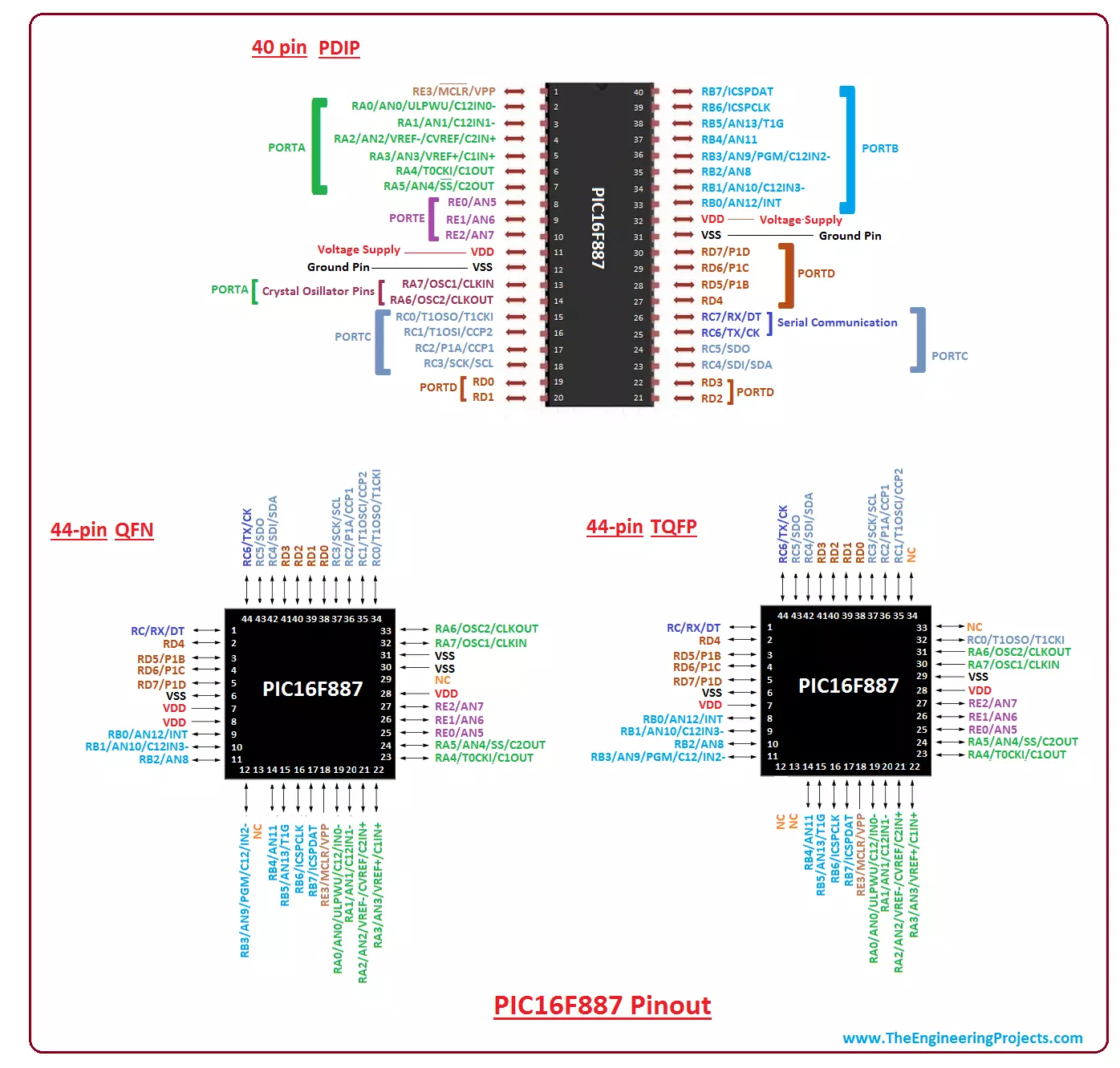
Hey Guys! Hope you are doing well. This is a platform where we keep you updated with valuable information so you keep coming back for what we have to offer. Today, I'll uncover the details on the Introduction to PIC16F887. It is a 40-pin PIC microcontroller, introduced by Microchip, and is a successor of PIC16F877A. Microcontrollers have revitalized the technology by providing a flawless interface and an ability to perform numbers of functions on a single chip. Gone are days, when you had to rely on external components to develop your projects which might be time-consuming, covered more space, and required a number of prior skills before making your project in real time. Microcontrollers have made things easy by covering each and every aspect of the projects that are directly or remotely related to automation. In this tutorial, I'll discuss each and everything related to PIC16F887 including its main features, working, pinout and applications. Let's jump right in and nail down everything you need to know.

Introduction to PIC16F887

  • PIC16F887 is a 40-pin (for PDIP package) and 8-bit CMOS PIC Microcontroller that comes with nanoWatt technology. Economical price and user-friendly architecture make this device easy to use and easy to configure.
  • It is available in three packages known as PDIP, QFN, and TQFP. The first one comes with a 40-pin layout design while remaining two contains 44 pins on each layout.
  • This PIC version, like other models in the PIC community, contains everything that is required to make an embedded system and drive automation.
  • The PIC16F887 incorporates 256 bytes of EEPROM data memory, 368 bytes of RAM, and program memory of 8K.
  • Apart from self-programming capability, it also contains 2 Comparators,10-bit Analog-to-Digital (A/D) converter with 14 channels, and capture, compare and PWM functions.
  • The asynchronous serial port is added on the chip that can be configured both ways i.e. the 2-wire Inter-Integrated Circuit (I²C™) Bus or 3-wire Serial Peripheral Interface (SPI™)
  • The Enhanced Universal Asynchronous Receiver Transmitter (EUSART) feature makes this chip compatible with the devices where serial communication is an integral part of the project.
  • The functions that make this device unique in terms of ease of use include
  1. Power-Saving Sleep mode
  2. Industrial and Extended Temperature range
  3. Wide operating voltage range (2.0V-5.5V)
  4. SR Latch mode
  5. Power-up Timer (PWRT) and Oscillator Start-up Timer (OST)
  6. Power-on Reset (POR)
  7. Ultra-Low-Power Wake-up (ULPWU)
  8. Multiplexed Master Clear with pull-up/input pin
  9. Individually programmable weak pull-ups
  10. Brown-out Reset (BOR) with software control option
  11. Enhanced low-current Watchdog Timer (WDT)
  • Needless to say, this PIC version is an ideal choice to drive A/D conversion in automotive, consumer, and industrial applications.

1. PIC16F887 Pinout & Description

Getting a hold of Pinout and Pin descriptions is mandatory to check the working of each pin on this tiny chip. If you are a newbie or an expert, you need to know the function associated with each pin for a better understanding of the chip.
Pinout
The following figure shows the complete pinout of all three packages called PDIP, QFN, and TQFP.

  • As described earlier, the PDIP package contains 40-pin while other two come with 44 pins.
Pin Description
PIC16F887 is widely used in many electronic applications. Some pins in the controller are capable of doing more than one functions that allow us to use the pin according to the needs and demands of the project. I have listed the function of each pin in the following table.
Pin# Pin Name Pin Description
2 RA0 AN0/ULPWU C12IN0- Digital I/O Pin Analog Input 0 Pin Comparator
3 RA1 AN1/ULPWU C12IN1- Digital I/O Pin Analog Input 1 Pin Comparator
4 RA2 AN2 C2IN+ VREF-/CVREF Digital I/O Pin Analog Input 2 Pin Comparator ADC Reference Input Voltage (low)
5 RA3 AN3 C1IN+ VREF+ Digital I/O Pin Analog Input 3 Pin Comparator ADC Reference Input Voltage (high)
6 RA4 C1OUT T0CKI Digital I/O Pin Comparator External clock input for Timer0
7 RA5 AN4 C2OUT SS Digital I/O Pin Analog Input 4 Pin Comparator Slave Select input for SPI
33 RB0 AN12 IOC/INT Digital I/O Pin Analog Pin Interrupt-on-change
34 RB1 AN10 C12IN3- IOC Digital I/O Pin Analog Pin Comparator Interrupt-on-change
35 RB2 AN8 IOC Digital I/O Pin Analog Pin Interrupt-on-change
36 RB3 AN9 C12IN2- IOC PGM Digital I/O Pin Analog Pin Comparator Interrupt-on-change Basic
37 RB4 AN11 IOC Digital I/O Pin Analog Pin Interrupt-on-change
38 RB5 AN13 T1G IOC Digital I/O Pin Analog Pin Timer Interrupt-on-change
39 RB6 IOC ICSPCLK Digital I/O Pin Interrupt-on-change pin Basic
40 RB7 IOC ICSPDAT Digital I/O Pin Interrupt-on-change pin Basic
15 RC0 T1OSO/T1CKI Digital I/O Pin Timer
16 RC1 T1OSI CCP2 Digital I/O Pin Timer ECCP
17 RC2 CCP1/P1A Digital I/O Pin ECCP
18 RC3 SCK/SCL Digital I/O Pin MSSP
23 RC5/SDO RC5 SDO Digital I/O Pin SPI Data-Out Pin
24 RC5 SD0 Digital I/O Pin MSSP
25 RC6 TX/CK Digital I/O Pin USART
26 RC7 RX/DT Digital I/O Pin USART
19 RD0 Digital I/O Pin
20 RD1 Digital I/O Pin
21 RD2 Digital I/O Pin
22 RD3 Digital I/O Pin
27 RD4 Digital I/O Pin
28 RD5 P1B Digital I/O Pin ECCP
29 RD6 P1C Digital I/O Pin ECCP
30 RD7 P1D Digital I/O Pin ECCP
8 RE0 AN5 Digital I/O Pin Analog Pin
9 RE1 AN6 Digital I/O Pin Analog Pin
10 RE2 AN7 Digital I/O Pin Analog Pin
13 RA7 OSC1 CLKIN Crystal Oscillator Input Pin
14 RA6 OSC2 CLKOUT Crystal Oscillator Output Pin
1 RE3 MCLR VPP ICSP Programming Enable Pin Master Clear Active Low Reset Pin
11,32 VDD Voltage Supply Pin
12,31 VSS Ground Pin

2. PIC16F887 Features

You can anticipate the nature of any device by looking at its main features. Following table shows the complete features of PIC16F887.
PIC16F887 Features
No. of Pins 40
CPU 8-Bit PIC
Operating Voltage 2 to 5.5 V
Program Memory 8K
Program Memory (Instructions) 8192
RAM 368 Bytes
EEPROM 256 Bytes
ADC 10-Bit
I/O Ports (5) I/O Pins A,B,C,D,E 35
Packages 40-pin PDIP 44-pin QFN 44-pin TQFP
External Oscillator up to 20 MHz
Timer (3) 16-Bit Timer (1) 8-Bit Timer (2)
USART Protocol 1
I2C Protocol Yes
SPI Protocol Yes
Brown-out Reset Yes
Watchdog Timer Yes
Comparators 2
Master Synchronous Serial Port (MSSP) module 1
Capture/Compare/PWM 16bit/16bit/10bit
Power Saving Sleep Mode Yes
Selectable Oscillator Option Yes
Operating Current 11uA at 32 kHz, 2.0 V 220uA at 4 MHz, 2.0 V
Temperature Range -40 to 125
Oscillator Start-up Timer Yes
  • Checking main features before purchasing of the controller will help you analyze and develop your required project.
  • Power on reset and selectable oscillator options are some unique features included in the chip.

3. PIC16F887 Functions

This PIC model performs many functions that are quite similar to the function in other controllers of the PIC community. Following are the main functions of PIC16F887.
Timer
PIC16F887 contains one 16-bit timer and two 8-bit timers that can be used in both ways i.e. timer and counter and comes with internal and external clock select capability. The timer mode is used to increment the instruction cycle while counter mode increments the rising and falling edge of the pin. When the bit T0CS (OPTION_REG<5>) is set, the counter mode will be selected and when it is cleared, the timer mode will be selected.
Brown Out Reset (BOR)
The BOR is a function that brings the controller to reset once the Vdd (voltage supply) drops below a brownout threshold voltage. There is a fine line between a BOR and Power On Reset, where the whole range of voltages is provided to protect the chip once the power drops at the voltage supply line. In order to put the delay, mostly recommended, in returning from a BOR function, the Power Up Timer must be kept enabled. Apart from controlling through software, the BOR mode can also be handled and configured through BOREN settings in a register.
USART
PIC16F887 comes with enhanced USART module. This module consists of TX - A transmission pin used for transmitting serial data to other devices and RX - A receive pin used for receiving serial data.
Watchdog Timer
PIC16F887 comes with built-in watchdog timer that is mainly used to reset the controller when a program hangs up during compilation or gets stuck in the infinite loop of the program. It is important to note the timer must be reset to the initial value after every 3 instructions in order to avoid it going to zero value in normal conditions. The watchdog timer is nothing but a countdown timer and starts from 1000 and gradually goes down to zero.
Power On Reset
Power On Reset function resets the controller when it is powered on. If there comes unknown error in the chip, powering on the device will exclude it from the loop of running program and saves the device from malfunctioning.
Sleep Mode
Power saving sleep function generates a low current power down mode. This sleep mode can be terminated using an interrupt, watchdog timer or external reset.

4. PIC Compiler

  • Microchip has introduced its own standard compiler for the PIC controller called MPLAB C18 Compiler. You can download this compiler online from the Microchip Official Site.
  • The code written in the compiler creates a hex file that is transferred to the microcontroller to execute the certain function.
  • Third party softwares are also available for compiling the program and MikroC Pro For PIC is mainly used for this purpose.
  • These Top 3 PIC C Compilers give you the flexibility to pick any compiler based on your needs and requirements.
  • The PICKit3 is mainly used for burning the code in the controller which is a standard PIC burner. There are other unofficial burners also available but PICKit3 is mostly preferred for the PIC controllers.

5. PIC16F887 Memory Layout and Working

The whole memory in this controller is distributed into three main types known as EEPROM, RAM and ROM Memory. All of them plays a vital role in the controller in terms of executing and calling instructions with some exceptions. Let's discuss each of them one by one.
ROM Memory
ROM memory, also known as Non-Volatile memory, which stores the running program permanently and is not dependent on the power supply i.e. has an ability to retain the program if the power supply is removed. The ROM memory is about 8K made with FLASH Technology.
EEPROM Memory
This memory is quite similar to ROM memory in one way or the other in terms of storing running program permanently with the exception i.e. the instructions in EEPROM can be modified during the operation of the controller. It contains memory space around 256 bytes, quite less than ROM memory, but enough to store the program permanently.
RAM Memory
RAM memory, also known as volatile memory, is divided into two main parts known as general-purpose registers (GPR) and special-function registers (SFR). This memory is volatile in nature as it stores the program temporarily and is power dependent i.e. once the power supply is turned off the instructions stored in the RAM will be removed.
  • Registers in the RAM memory are the data holding places in the controller. A single register can hold instruction, storage address, and any kind of data including bit sequence or individual characters.
Registers are classified into two banks called Bank 1 and Bank 2 where registers from 00H to 0BH and 80H to 8BH fall under the category of SFRs and remaining are GPRs.
  • Each bank contains128 bytes of memory space where first 12 locations are reserved for SFR while remaining are reserved for GPR.
Let’s discuss few registers in details. STATUS. This register plays a role to switch between the banks. Setting fifth bit of this register shows we are discussing bank 1 while resetting it will indicate we are discussing bank 0. TRISA. This register is used to configure PORTA as an input or output. The value 1 shows output and value 0 shows input. TRISB. This register is identical to the TRISA in terms of deciding the pins as an input or output and used for PORTB. W Register. All registers mentioned above are SFRs while W register is a GPR. It is not a part of any register bank and is accessible by the program only. The desired values are written on W register and transferred to the target register before writing them on the PORTA or PORTB.

6. PIC16F887 Block Diagram

The following figure shows the block diagram of PIC16F887.
  • The program memory comes with 8K memory space which can configure 8192 words.
  • Some pins can be interfaced with other functions of multiple devices including external interrupt, Timer0 clock input and Change on PORTB interrupt.

7. PIC16F887 Projects and Applications

  • PIC16F887 is mainly used in students project i.e. controlling motors and sensor interfacing.
  • Used in Central heating projects
  • Production of temperature data logger
  • Serial Communication
  • Used in health and security systems
  • Gas sensor projects
  • Embedded system
  • Used in industrial automation

8. Why Use PIC MicroControllers

PIC microcontrollers are widely used in most of the electronic applications because they offer easy to use interface that requires no prior skills for getting a hands-on experience with the module. These controllers are cheap and come with an ability to perform a number of functions using minimum circuitry. PIC controllers have outperformed Atmel controller like 8051 in terms of their efficiency and higher processing speed. More often than not, automation industries prefer and use these controllers for carrying out different operations as they offer very little power consumption. That’s all for today. I hope I have given you everything related to PIC16F887. If you are unsure or have any query, you can ask me in the comment section below. I’d love to help you in any way I can. You are most welcome to give your feedback and suggestions, they help us provide you quality work as per your needs and demands. Thanks for reading the article.
Syed Zain Nasir

I am Syed Zain Nasir, the founder of <a href=https://www.TheEngineeringProjects.com/>The Engineering Projects</a> (TEP). I am a programmer since 2009 before that I just search things, make small projects and now I am sharing my knowledge through this platform.I also work as a freelancer and did many projects related to programming and electrical circuitry. <a href=https://plus.google.com/+SyedZainNasir/>My Google Profile+</a>

Share
Published by
Syed Zain Nasir