How to use while Loop in C#

Hello friends, I hope you all are great. Today, I am posting 10th tutorial in C# series and its about How to use while Loop in C#. It's gonna be a quick tutorial, as there's not much to discuss. In our 8th tutorial in C# series, we have had a look at How to use IF Loop in C# and we have seen that IF loop takes a Boolean expression and if it's TRUE then it allows the compiler to enter in it just once. While loop is quite similar to IF loop as it takes a Boolean expression as well but it will keep on executing again & again, so let's have a look at it in detail:

How to use while Loop in C#

  • While Loop in C# takes a Boolean expression as a condition and it will keep on executing as long as the conditional expression returns true, we can say Execute while condition is TRUE.
  • Here's the syntax of while loop:
while (Boolean Expression) { // Code will execute, while Boolean Expression is TRUE }
  • So, let's design a simple example to understand How while Loop works:
  • In schools, you must have studied math tables, so I have created a simple code using while loop which asks from the user to enter table of.
  • When user enters the number, the program will print out its table till 10.
  • If you look at the code, I have used while loop and this while loop will execute 10 times as the condition in while loop is TotalLength <= 10.
  • I have incremented this TotalLength variable in while Loop so when it will become 10, the while loop will stop.
  • So, instead of writing 10 lines to display table, we are just using while loop, we can also increase the lines to 20 or 30 quite easily, that's the benefit of while loop.
  • Let's play with the code a little and print values till 20 and also use IF Loop in this while loop, which we have studied in 8th lecture.
  • You can see in above code that I have increased the length to 20 and then in while Loop, I have used IF Loop.
  • IF the length is 10 then I am just adding blank lines to separate first 10 from last 10.
  • I hope you got the idea of How to use While Loop and what's its difference from IF Loop, the IF Loop executed just once when condition comes true.
  • Here's the complete code used in today's lecture:
using System;

namespace TEPProject
{
    class Program
    {
        static void Main(string[] args)
        {
            
            Console.Write("Enter Table of : ");
            int TableOf = int.Parse(Console.ReadLine());

            int TotalLength = 1;

            while (TotalLength <= 20)
            {
                int TableValue = TotalLength * TableOf;
                Console.WriteLine("{0} x {1} = {2}", TableOf, TotalLength, TableValue);
                if(TotalLength==10)
                {
                    Console.WriteLine("\n");
                }
                TotalLength++;
            }
            Console.WriteLine("\n\n");
            
        }
    }
}
So, that was all about How to use while Loop in C#. In our coming tutorial, we will have a loop at How to use do While Loop in C#. Till then take care !!! :)

How to use switch Statement in C#

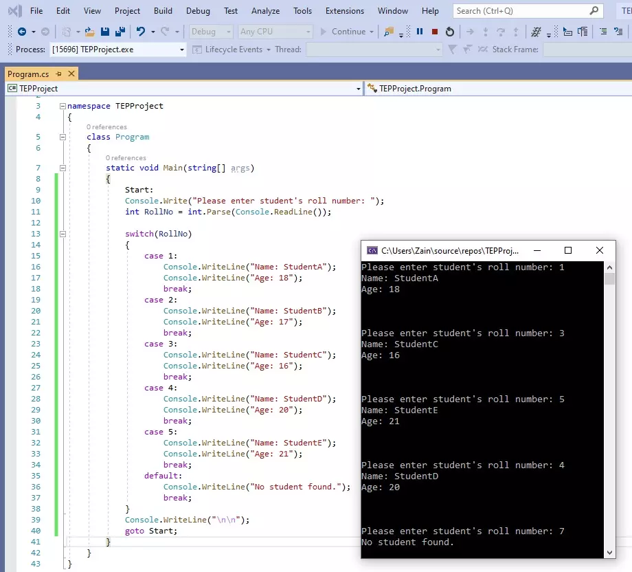
Hello friends, I hope you all are doing great. In today's tutorial, we are gonna have a look at How to use switch Statement in C# and its our 9th tutorial in C# series. In our previous tutorial, we have seen IF Loop in C# and this switch statement is also a loop but works slightly different than IF loop and it totally depends on your application, which one you want to use. First we will have a look at How to use switch statement in C# and after that we will also study goto statement, because switch and goto statements are normally used together. So, let's get started with it:

How to use switch Statement in C#

  • Switch Statement is a loop in C# which takes a variable as a condition, and then creates its different cases and we can deal each case separately.
  • We need to use break Statement after every case Statement to get out of the switch Statement.
  • We can also use default Statement at the end of switch Statement, which will execute if none of the cases are true.
  • So let's have a look at the syntax of switch statement in C#:
switch (variable) { case value1: // This case will execute, if variable = value1 break; case value2: // This case will execute, if variable = value2 break; . . . case valueN: // This case will execute, if variable = valueN break; default: // default will execute, if all the above cases are false. break; }
  • As you can see in above syntax, we have first used switch keyword and then took a variable, this variable can have any datatype.
  • Then we have created different cases, we can create as many cases as we want and each case has a value so if the variable is equal to that value then respective case will execute.
  • Let's understand it with an example: Let's design a project where we display information of class students using their roll number, so we will take their roll numbers as an input and will display the respective student's data using switch case statement:
  • As you can see in the above figure that I have first asked for the student's Roll Number and then placed a switch statement and provided RollNo as a conditional variable.
  • After that in each case I have placed the roll no value and for each roll number I have added the name and age of the user.
  • In execution, I have entered 1 and the code has provided me data placed in case 1 and have ignored all the other cases as well as the default case.
  • But if you run this code then you will realize that it asks for the Roll number only once but what if we want it to run again & again.
  • We can use goto Statement for that purpose, although it's not the best way to create loop but one of the ways and you should know about it.
  • In above code, I have just added two lines of code, first I have placed a tag Start: at the top of the code and then at the end I have used goTo Start;
  • So, at the goto Statement, the compiler will find the tag mentioned and will move on to that position and will start executing the code, so it's kind of an infinite loop which is never gonna stop.
  • Here's the final code, which you can test in visual studio:
using System;

namespace TEPProject
{
    class Program
    {
        static void Main(string[] args)
        {
            Start:
            Console.Write("Please enter student's roll number: ");
            int RollNo = int.Parse(Console.ReadLine());
            
            switch(RollNo)
            {
                case 1:
                    Console.WriteLine("Name: StudentA");
                    Console.WriteLine("Age: 18");
                    break;
                case 2:
                    Console.WriteLine("Name: StudentB");
                    Console.WriteLine("Age: 17");
                    break;
                case 3:
                    Console.WriteLine("Name: StudentC");
                    Console.WriteLine("Age: 16");
                    break;
                case 4:
                    Console.WriteLine("Name: StudentD");
                    Console.WriteLine("Age: 20");
                    break;
                case 5:
                    Console.WriteLine("Name: StudentE");
                    Console.WriteLine("Age: 21");
                    break;
                default:
                    Console.WriteLine("No student found.");
                    break;
            }
            Console.WriteLine("\n\n");
            goto Start;
        }
    }
}

So, that was all about How to use switch Statement in C#. If you need any help then ask in comments. Will meet you in next tutorial. Till then take care !!! :)

What is Thyristor

Hello friends, I hope you all are doing great. In today’s tutorial, we will have a look at What is Thyristor. The thyristor is a semiconductor component that has 4 layers of N and P materials with the sequence P, N, P, N. First thyristor was invented in 1950 by William Shockley who was a physicist and belonged to the United States of America. But first time it was practically used in 1956 due to its huge amount of current and voltage handling capability. Due to this feature, it was commonly used in different power control circuitry, fan dimmers, and speed control of different motors. There are 2 types of design in which this module available and both used according to circuit requirements first one has two leads and the second one has three leads in its structure. This electronic component is mostly used in switching circuitry, oscillators, level detection circuits, etc. This module is not similar to the transistor as a transistor can operate among on and off conditions but thyristor operates only single state either on or off. In today's post, we will have a look at its working, structure, pinout, applications and some related parameter. So let's get started with What is Thyristor.

What is Thyristor

  • A thyristor is also known as SCR (silicon controlled rectifiers) used in different switching circuits like a transistor and in power controlling circuitry.
  • The physical structure of this semiconductor is different than the other semiconductors materials like transistor that has three layers but in thyristor 4 layers of different elements are constructed.
  • In a normal transistor, there are 3 P, N, P or N, P, N layer exists but in while in thyristor four-layer like P, N, P, N exists.
  • Its 'P' end is known as anode and 'N' end is known as the cathode. As in normal transistor base control terminal in this device, the control terminal is known as a gate that is adjacent to the cathode.
  •  This module can be created with the different semiconductor materials but normal it is manufactured with the silicon.
  • As the silicone has the ability to handle larger amperes current and voltage easily as well it has ability to bear high temperature so it mostly preferred for thyristor construction.
  • with these features, its price and construction are simple so it prefered for thyristor and some other electronic devices.

 Working of Thyristor

  • The working of this module is different than other semiconductors device, to the understanding of working of this device we draw the equivalent circuit.
  • In the given figure you can see that two transistors are linked with one another the first transistor is NPN that is behaving like the anode and the second transistor is PNP that is behaving like the cathode.
  • If we provide input supply to at the terminals of thyristor there will be no current passes as the both of transistor ane unbiased state.
  • If we connect input supply at the gate then current will passes through the base that will operate the TR2 transistor.
  • When TR2 starts its operation than the base of the first transistor get force from this transistor and start its operation it causes to put TR2 in working state either we separated the input supply.

Features of Thyristor

  • These are some features of thyristor that are described here with detailed.
    Specifications                                         Parameters
    dI/dt Extreme increment of on-state current It is an extreme value of current for on condition if it surpasses then our device will be damaged.
    IGM Maximum Gate Current It is the extreme value at the gate that it can bear.
    IGT Triggering current of the gate It is the triggering value of current at the gate that also starts to current flow through anode and cathode terminals of component.
    I2t Overcurrent protection The I2t parameter tells about the value of fuse used for this module.
    IT(AV) On condition average current This parameter of thyristor explains about the average value of current passing through the module.

Types of Thyristor

  • There are numerous types of thyristor according to their use and structure.
RCT:
  • One important feature of thyristor is that it stops current to flow in reverse direction so if we add and diode then current starts to flow in the opposite direction. This type of arrangement is known as RCT or reverse conducting thyristor.
  • During reverse operation both thyristor and diode not operate at the same time but they take some time for the operation that provides protection from overheating.
  • This type of thyristor used in inverter circuits and frequency regulators.
GATT:
  • This types of thyristor are used in such applications where fast switching needs. For this process in certain cases, negative polarity voltage also provided to the gate.
  • To control the voltage at cathode and anode terminals negative voltage at the gate control the minorities carriers.
  • The physical construction of thyristor is like to normal thyristor but the difference is that the area of cathode that enhances the controlling capability of the gate.
GTO:
  • It is also known switch for a gate of thyristor. This types of thyristor are not normally used in circuits because they not operate at reverse voltage.
Asymmetric Thyristor:
  • In such circuits where there is no use reverse voltage and no need of rectifier circuit this type of thyristor is used. These are normally used in switching circuits.

Applications of Thyristor

  • The thyristor is normally used in different electronic circuits and devices, its some practical uses are explained here with the detailed.
  • It used in different electrical devices for the controlling of alternating current at the input such as motor, light etc.
  • It used in different circuits as a switch.
  • In a different circuit, it used to control the overvoltage.
  • It used in different controllers as a trigger.
  • It also used in camera for flashing of a photograph.
It is the detailed tutorial on thyristor in this post I have mentioned each and everything related to the thyristor. If you still have any question about it ask in comments. Thanks for reading.  

Introduction to LCD 16x2

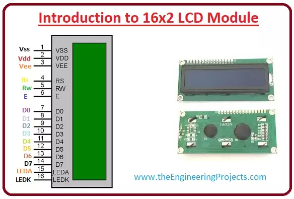
Hello friends, I hope you all are doing great. In today’s tutorial, we will have a look at Introduction to 16x2 LCD Module. LCD stands for liquid crystal display it is mostly used in different electronic projects and devices to display different values. LCD uses liquid crystals for the generation of visible images. 16 x 2 liquid crystal display is a basic LCD module used in DIY electronic projects and circuits. In this LCD module, there are two rows every row consists of sixteen numbers.

With the two rows in this module, there are sixteen columns. The VA dimensions of these modules are (66 x 16) millimeters and the thickness is 13.2 millimeters. Its operating voltage is plus five or plus three volts. In today's post, we will have a look at working, applications, circuits,  features, advantages and disadvantages. So let's get started with Introduction to 16x2 LCD Module.

Where To Buy?
No.ComponentsDistributorLink To Buy
1LCD 16x2AmazonBuy Now

Introduction to 16x2 LCD Module

  • LCD(liquid crystal display) is normally used in embedded projects due to its low cost, easy access and flexibility to get programmed.
  • Almost every electronic device we daily see like in you mobile, calculator and some other devices.
  • There is a type of liquid display that has sixteen column and two rows so it is known as 16 x 2 LCD modules.
  • LCD also available in different arrangements like (8 x 1), (10 x 2), (16 x 1), but the 16 x 2 liquid crystal is normally used in embedded projects.
  • In this liquid crystal display, there are thirty-two characters and each of them consists of 5 x 8 pixels.
  • So we can say that character consists of forty pixels or dots and total pixels in this liquid crystal display can be fined as (32 x 40) or 1280 pixels.
  • During its interfacing with a microcontroller, it makes sure that liquid crystal display should be directed about the locations of pixels.

Pinout of 16x2 LCD Module

  • These are the main pinouts of 16 x 2 LCD that are described here with the detailed
Pin No: Pin Name:                                         Parameters
Pin#1  Ground This pin is used to connect the ground.
Pin#2  +5 Volt At this pinout plus five volts are applied to on the LCD.
Pin#3 VE This pin used to select the contract of the display.
Pin#4 Register Select This pinout is used to MCU controller connected led to a shift from command to data mode.
Pin#5 Read and Write It used for reading and wiring of data.
Pin#6 Enable It linked with the MCU to toggle among zero and one.
Pin#7 Data Pin 0 The pinouts from zero to seven are data pinouts and these are linked with the MCU for transmission of data. This liquid crystal module can also operate on the four-bit mode by working on o, 1, 2, and 3 pinouts and others are free.  
Pin#8 Data Pin 1
Pin#9 Data Pin 2
Pin#10 Data Pin 3
Pin#11 Data Pin 4
Pin#12 Data Pin 5
Pin#13 Data Pin 6
Pin#14 Data Pin 7
Pin#15 LED Positive This pinout is for turn backlight of led into positive.
Pin#16 LED Negative Backlight liquid crystal display pinout negative terminal.

Command codes for 16x2 LCD Module

  • These are some commands codes for 16 x2 LCD modules.
Sr.No Hex Code                                         Parameters
1  1 This command will remove data displaying on the screen of lcd.
2  2 It used to move back home.
3 4 It used to change location of a cursor to left side.
4 6 It changes the position of cursor to right side.
5 5 It used for shift display on right.
6 7 It used for Shift display one  left
7 8 It used to off the display and cursor will also off.  
8 0A It used for both display off, a cursor on.
9 0C It used for display on, cursor also off.
10 0E By using this command we can on display, the cursor  will be blinking
11 0F By this command Display will be on, the cursor also blinking.
12 10 It changes the location of a cursor to left.
13 14 It set cursor location to right.
14 18 It changes the location of the complete display to the left side.
15 1C It changes the location of the complete display to right side.
16 80 It used to move the cursor to the first line.
17 C0 It send the cursor to starting of the second line.
18 38 2 lines and 5×7 matrix.

Features of 16x2 LCD Module

  • These are some features of 16x2 LCD Module that are described with the detailed.
  • Its functioning voltages are from 4.7 volts to 5.3 volts.
  • It uses one milliampere current for operation.
  • In this liquid crystal display, we can work both alphabets and numbers.
  • On this module, there are rows each has sixteen characters.
  • Every character of this board has 5 x 8 or 40 pixels.
  • It works on both four and eight bits mode.
  • It display screen backlight is two colour green and blue.

Registers of LCD

  • In this module there are 2 main types of register first one is data register and the second one is command register. The RS pinout is used for the change the register.
  • If we set zero then the register is command and at one data register will work.
  • Now we discuss these two registers with the detailed.
Command Register
  • The main function of this register is to save instructions shown on display.
  • That help to a clearing of data changes the location of the cursor and display control.
Data Register
  • This register saves the date to display on the liquid crystal screen. When we send data to liquid crystal display it moves to the data register, processing of that data will initiate.
  • If we set the value of register at one then the data register will start operation.

So it is the detailed article on the 16x2 LCD Module if you have any question about ask in comments. Thanks for reading.

Syed Zain Nasir

I am Syed Zain Nasir, the founder of <a href=https://www.TheEngineeringProjects.com/>The Engineering Projects</a> (TEP). I am a programmer since 2009 before that I just search things, make small projects and now I am sharing my knowledge through this platform.I also work as a freelancer and did many projects related to programming and electrical circuitry. <a href=https://plus.google.com/+SyedZainNasir/>My Google Profile+</a>

Share
Published by
Syed Zain Nasir