Analog Input Scaling in Ladder Logic Programming

Hi friends and hope you are doing very well. Today we would like to take one tutorial which is very essential in the industry which is analog input processing for handling analog measurements of physical signals like temperature, humidity, pressure, distance, flow and level of liquids, etc. Typically, sensors produce two types of analog signals to represent the equivalent measured signal which is current and voltage signals. The currently produced signals would be within the range of 4-20 mAwhile voltage signals are in the range of 0-10 v. because, that output signals represent physical signals, the limits of output signals are 0 to 10 v for voltage based sensors and 4 to 20 mA for current-based sensors, these values should be scaled to represent the equivalent value as regards to physical signals. By completing this tutorial, we will have elaborated on the concept of handling analog signals and how we scale them to represent the physical signals. In addition, we will go through practical examples for handling analog inputs with ladder programming and then we will enjoy practicing these examples on the simulator to validate the written ladder code and show practically the analog processing in PLC.

In computer systems, plc, and microcontrollers all processing work that has been done inside is processed in digital which is 0 and 1 representation. So, one may ask how analog signals which change continuously within a specific range could be processed by computers, PLCs, or microcontrollers? Well, that is an exciting question and its answer will open the door to show the aim of this tutorial. Figure 1 shows an example of analog signals of the voltage that represents the temperature sensor reading.

Fig. 1: Output voltage of temperature sensor

As you see in fig. 1, the output of the temperature sensor would be either a voltage signal or a current signal based on the type of the sensor. And the output of sensors is applied to the analog input module that converts the analog signal to a digital signal to be processed digitally by the PLC.

Scaling analog inputs

The output signals of sensors either voltage or current signal should be scaled to represent the physical signal and at the same time, it has its equivalent digital values. For example, let the temperature that is being measured has a range between 0 to 100 °C, and the sensor that we use produces voltage output from 0 to 10 v. Therefore, each 0.1 v change in voltage is equivalent to a change of 1°C. Also, assuming the maximum digital value that can be received is 4000. So, 0 V is equivalent to 0 as a digital value and 10 voltage is equivalent to 4000 as a digital value. So, it is crucial to scale the output voltage to determine accurately the equivalent change in sensors’ reading in terms of voltage to represent the temperature in digital value and the real range of the physical signal.

Scaling with parameters

Again, we have two sides to be scaled from one to the other. Therefore, the parameters that are needed for achieving such scaling are as follows:

  • The input value: represents the physical signal that comes out from a sensor. And it typically could be from 0-10v for voltage-based sensors, or it could be 4-20mA for current sensors type.
  • The scaled value represents the digital equivalent of that value. And it depends on the word size or the number of bits that we use for representation in digital format. For example, for 16 bits size, the scaled value is up to which is +/- 32768.

So we can imagine together now the scaling function block in ladder logic should be as shown in fig. 2. It shows the input minimum and maximum which could be 0 and 10v or 4 and 20mA. In addition, there are scaled min and max which could be from 0 to 32768 for 16 bits size conversion.

Fig.2: the SCP block in Allen Bradley

Analog input processing in Ladder logic

We are going to show a complete example of analog input processing in Siemens and AB as well to present the merits of analog conversion in both brands. Figure 3 shows a primitive rung of the ladder logic program that processes the analog input reading. The ladder rung uses a scaling with parameters (SCP) block that includes an input minimum of 4mA and an input maximum of 20mA. And it uses a scaled range from 0 to 32767 because it utilizes 16-bits word for representing the digital data.

Fig. 3: Ladder logic rung for analog input processing

Figure 4 shows the run of the simple example which shows up the processing of analog inputs. It shows that, when the input measured value was 12mA, the output was 16884 which is pretty accurate. It is good to mention that, the output is limited to be within the range of the scaled min and max meaning that it should be from 0 to 32767.

Fig. 4: Testing analog processing by the simulator

Let us give another example but in siemens s7-1200 which is represented by Fig. 5. The ladder code is very simple and it consists of two runs as shown in fig. 5; the first one is for validating the reading to be within the range which is from 0 to 27648 and the second rung is the main one which performs the analog processing in two steps. Firstly it normalizes the input based on the aforementioned range and then it scales the output back to represent it in the output signal format. In this example, we measure a battery voltage that is typically located in the range of 0 to 12v. Therefore, the min and max parameters in the scale_X block should be 0 and 12 v respectively.

Fig. 5: Example of processing analog inputs in Siemens S7-1200

Figure 6 demonstrates the test of the analog processing showing the output reported 5.858941 when the reading was 13499 which is high accuracy.

Fig. 6: Simulation of processing analog inputs in Siemens S7-1200

What’s next

I am truly thrilled to have you shared with me such a very important tutorial about analog input processing and scaling with parameters because this is a very common operation you might see in every operation in the industry as there are hundreds of sensors that read analog physical signals and be processed by the controller for deciding the next stage of the operation. Next time we are going to talk about jumping and branching techniques in the ladder logic program. So please be ready to meet very soon and learn together and enjoy practicing plc ladder programming

Interfacing PIR Motion Sensor and Raspberry Pi Pico Module with MicroPython

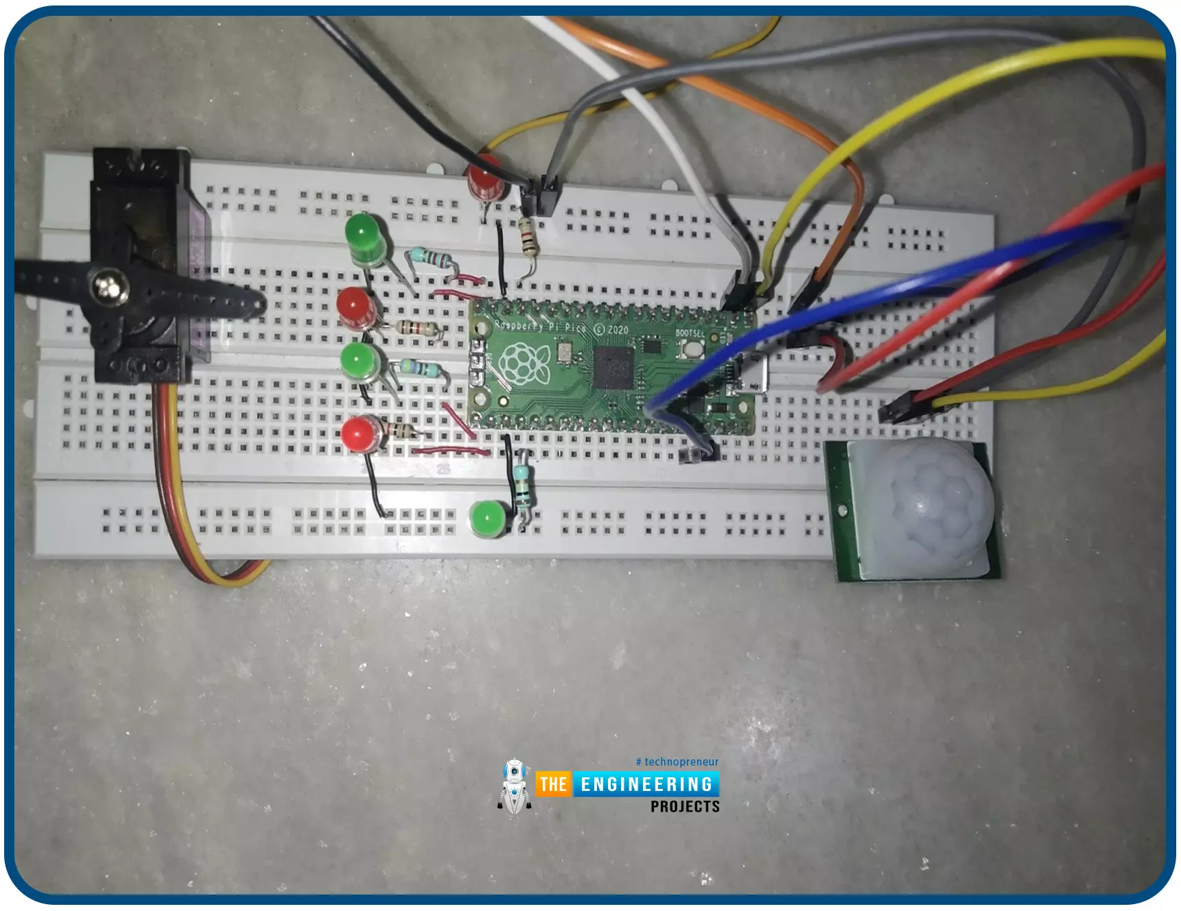
Hello readers, I hope you all are doing great. In this tutorial, we will learn how to interface the PIR sensor to detect motion with the Raspberry Pi Pico module and MicroPython programming language. Later in this tutorial, we will also discuss the interrupts and how to generate an external interrupt with a PIR sensor.

Before interfacing and programming, the PIR and Pico boards let’s first have a look at the quick introduction to the PIR sensor and its working.

Fig. 1 Raspberry Pi Pico and PIR sensor

PIR motion sensor and its working

PIR stands for Passive Infrared sensors and the PIR module we are using is HC-SR501. As the name suggests the PIR or passive infrared sensor, produces TTL (transistor transistor logic) output (that is either HIGHT or LOW) in response to the input infrared radiation. The HC-SR501 (PIR) module is featured a pair of pyroelectric sensors to detect heat energy in the surrounding environment. Both the sensors sit beside each other, and when a motion is detected or the signal differential between the two sensors changes the PIR motion sensor will return a LOW result (logic zero volts). It means that you must wait for the pin to go low in the code. When the pin goes low, the desired function can be called.

In the PIR module, a fresnel lens is used to focus all the incoming infrared radiation to the PIR sensor.

Fig. 2 PIR motion sensor

The PIR motion sensor has a few setting options available to control or change its behaviour.

Two potentiometers are available in the HC-SR501 module as shown in the image attached below (Fig. 3). Sensitivity will be one of the options. So, one of the potentiometers is used to control the sensing range or sensitivity of the module. The sensitivity can be adjusted based on the installation location and project requirements. The second potentiometer (or the tuning option) is to control the delay time. Basically, this specifies how long the detection output should be active. It can be set to turn on for as little as a few seconds or as long as a few minutes.

Fig. 3 HC-SR501 PIR sensor module

Thermal sensing applications, such as security and motion detection, make use of PIR sensors. They're frequently used in security alarms, motion detection alarms, and automatic lighting applications.

Some of the basic technical specifications of HC-SR501 (PIR) sensor module are:

Table: 1 HC-SR501 technical specification

Hardware and software components required

  1. Raspberry Pi Pico development board
  2. PIR motion sensor (HC-SR5010
  3. Jumper wires
  4. Breadboard
  5. Thonny IDE (installed)
  6. USB cable

Fig. 4 Hardware components required

Interfacing the PIR sensor module with Raspberry Pi Pico

The HC-SR501 module has three interfacing pins VCC, GND and OUT. The VCC pin is to power up the board and should be connected to the 3.3V pin of the Raspberry Pi Pico board. The ‘OUT’ pin provides the TTL (Transistor-Transistor Logic) output. The TTL output is either High or LOW depending upon the electromagnetic input received. Raspberry Pi Pico module has 26 multifunctional GPIO pins. The ‘OUT’ pin of the PIR sensor can be connected to any of the GPIO pins of the Raspberry Pi Pico.

Table: 2 Interfacing HC-SR501 and Pico

Fig. 5 Interfacing PIR with Pico module

Programming with Thonny IDE and MicroPython

Before writing the MicroPython program make sure that you have the installed integrated development environment (IDE) to program the Pico board for interfacing the PIR sensor module.

There are multiple development environments available to program the Raspberry Pi Pico (RP2040) with MicroPython programming language like VS Code, uPyCraft IDE, Thonny IDE etc.

In this tutorial, we are using Thonny IDE with the MicroPython programming language (as mentioned earlier). We already published a tutorial on how to install the Thonny IDE for Raspberry Pi Pico Programming.

Now, let’s write the MicroPython program to interface the PIR (HC-SR501) and Pico modules and implement motion detection with Raspberry Pi Pico:

Importing Necessary Libraries

The first task is importing the necessary libraries and classes. To connect the data (OUT) pin of the PIR sensor module with Raspberry Pi Pico we can use any of the GPIO pins of the Pico module. So, here we are importing the ‘Pin’ class from the ‘machine’ library to access the GPIO pins of the Raspberry Pi Pico board.

Secondly, we are importing the ‘time’ library to access the internal clock of RP2040. This time module is used to add delay in program execution or between some events whenever required.

Fig. 6 Importing necessary libraries

Object Declaration

Next, we are declaring some objects. The ’led’ object represents the GPIO pin to which the LED is connected (representing the status of PIR output) and the pin is configured as an output.

The ‘PirSensor’ object represents the GPIO pin to which the ‘OUT’ pin of HC-SR501 is to be connected which is GPIO_0. The pin is configured as input and pulled down.

Fig. 7 Object declaration

Creating a function to detect motion

A ‘motion_det()’ function is defined to check the status of the PIR sensor and degenerate an event in response.

The status of the PIR sensor is observed using the ‘PirSensor.value()’ command. The default status of GPIO_0 is LOW or ‘0’ because it is pulled down. We are using a LED to represent the status of the PIR sensor. Whenever a motion is detected the LED will change its state and will remain in that state for a particular time interval.

If the motion is detected, the status of the GPIO_0 pin will turn to HIGH or ‘1’ and the respective status will be printed on the ‘Shell’ and simultaneously the status of led connected to GPIO_25 will also change to HIGH for 3sec. Otherwise, the “no motion” status will be printed on the Shell.

Fig. 8 creating a function

Running the motion detection function

Here we are using the ‘while’ loop to continuously run the motion detection function. So, the PIR sensor will be responding to the infrared input continuously with the added delay.

Fig. 9 mail loop

Code

# importing necessary libraries

from machine import Pin

import time

# Object declaration

led = Pin(25, Pin.OUT, Pin.PULL_DOWN)

PirSensor = Pin(0, Pin.IN, Pin.PULL_DOWN)

def motion_det():

if PirSensor.value() ==1: # status of PIR output

print("motion detected") # print the response

led.value(1)

time.sleep(3)

else:

print("no motion")

led.value(0)

time.sleep(1)

while True:

motion_det()


Results

    • Connect your Raspberry Pi Pico board with your system and select the MicroPython interpreter.
    • Create a new program in Thonny IDE and paste the above code.
    • Save the program to either on your system or on Raspberry Pi Pico.
    • To see the output result (printed) enable the ‘Shell’.
    • To enable the Shell got to View >> Shell.

Fig. 10 Fig enable Shell

  • Run the program by clicking on the ‘Run’

Fig. 11 Output on Shell

Fig. 12 Motion detected with LED ‘ON’

Generating External interrupt with Raspberry Pi Pico and PIR sensor modules

Now let’s take another example where we will discuss the interrupts with Raspberry Pi Pico.

Interrupts comes into existence in two conditions. First one is when a microcontroller is executing a task or a sequence of dedicated tasks and along with that continuously monitoring for an event to occur and then execute the task arriving with that particular event. So, instead of continuously monitoring for an event, a microcontroller can directly jump to a new task whenever an interrupt occurs meanwhile keeping the regular task on halt. Thus we can avoid the wastage memory and energy.

Fig. 13 Interrupt

In second case, a microcontroller will start executing the task only when an interrupt occurs. Otherwise the microcontroller will remain in standby or low power mode (as per the instruction provided).

In this example, we are going to implement the second case of interrupt. Where, we are using the PIR sensor to generate an interrupt. The Raspberry Pi Pico will execute the assigned task only after receiving an interrupt request.

Interrupts can either be external or an internal one. Internal interrupts are mostly software generated for example timer interrupts. On the other hand, external interrupts are mostly hardware generated for example using a push button, motion sensor, temperature sensor, light detector etc.

In this example, we are using the PIR sensor to generate an external interrupt. Whenever the motion is detected, a particular group of LEDs will turn ON (HIGH) while keeping rest of the LEDs in OFF (LOW) state. A servo motor is also interfaced with the Raspberry Pi Pico board. The motor will start rotating once an interrupt is being detected.

We already published tutorial on interfacing a servo motor with Raspberry Pi Pico. You can follow our site for more details.

Fig. 14 Schematic_2

Now let’s write the MicroPython program to generate an external interrupt for raspberry Pi Pico with PIR sensor.

Importing libraries

As we discussed earlier, in our previous example the first task is importing necessary libraries and classes. Rest of the modules , are similar to the previous example except the ‘PWM’ one.

The ‘PWM’ class from ‘machine’ library is used to implement the PWM on the servo motor interfaces with the raspberry Pi Pico board.

Fig. 15 importing libraries

Object Declaration

In this example, we are using three different components a PIR sensor, a servo motor, and some LEDs. Object are declared for each component. The object ‘ex_interrupt’ represents the GPIO pin to which the PIR sensor is connected where the pin is configured as an input one and pulled down.

The second object represents the GPIO pin to which the servo motor is connected. The ‘led_x’ object represents the GPIO pins to which the peripheral LEDs are connected. Here we are using six peripheral LEDs.

Fig. 16 Object declaration

  • We are declaring a global variable ‘pir_output’ to represent the status of PIR output or motion being detected or not. When no motion is detected the state of the variable will remain in default state that is ‘False’. Whenever the motion is detected the state of ‘pir_output’ variable will change to ‘True’ and an interrupt will be generated.

Fig. 17 PIR output status

Interrupt handler

Next we are defining a interrupt handler function. The Parameter ‘Pin’ in the function represents the GPIO pin caused the interrupt.

The variable ‘pir_output’ is assigned with a ‘True’ state value which will be executed only when an interrupt occurs (in the while loop).

Fig. 18 Interrupt handling function

Attaching interrupt to GPIO_0

Interrupt is attached to GPIO_0 pin represented with ‘ex_interrupt’ variable. The interrupt will be triggered on the rising edge.

Fig. 18 Attaching interrupt

Setting Servo motor position

In the function defined to change the position of servo motor we are using pulse width modulation technique to change the servo position/angle. The motor will rotate to 180 degree and then again back to 0 degree.

Fig. 19 defining function for servo

Motion_det()

This is the function where we are calling all the previously defined function and each function will be executed as per there assigned sequence whenever an interrupts is detected.

Fig. 20

Code

The MicroPython code to generate an external interrupt with PIR sensor for Raspberry Pi Pico is attached below:

# importing necessary libraries

from machine import Pin, PWM

import time

# Object declaration PIR, PWM and LED

ex_interrupt = Pin(0, Pin.IN, Pin.PULL_DOWN)

pwm = PWM(Pin(1))

led1 = Pin(13, Pin.OUT)

led2 = Pin(14, Pin.OUT)

led3 = Pin(15, Pin.OUT)

led4 = Pin(16, Pin.OUT)

led5 = Pin(17, Pin.OUT)

led6 = Pin(18, Pin.OUT)

# PIR output status

pir_output = False

# setting PWM frequency at 50Hz

pwm.freq(50)

# interrupt handling fucntion

def intr_handler(Pin):

global pir_output

pir_output = True

# attaching interrupt to GPIO_0

ex_interrupt.irq(trigger=Pin.IRQ_RISING, handler= intr_handler)

# defining LED blinking function

def led_blink_1():

led1.value(1)

led3.value(1)

led5.value(1)

led2.value(0)

led4.value(0)

led6.value(0)

time.sleep(0.5)

def led_blink_2():

led1.value(0)

led3.value(0)

led5.value(0)

led2.value(1)

led4.value(1)

led6.value(1)

time.sleep(0.5)

def servo():

for position in range(1000, 9000, 50): # changing angular position

pwm.duty_u16(position)

time.sleep(0.00001) # delay

for position in range(9000, 1000, -50):

pwm.duty_u16(position)

time.sleep(0.00001) # delay

def motion_det():

if pir_output: # status of PIR output

print("motion detected") # print the response

led_blink_1()

servo() # rotate servo motor (180 degree)

time.sleep(0.5)

pir_output == False

else:

print("no motion")

led_blink_2()

while True:

motion_det()

Result

The results observed are attached below:

Fig. 21 Output printed on Shell

  • For the hardware demonstration we are using six LEDs (3 red and 3 green) and a servo motor.
  • The Red LEDs represents the state whenever a motion is detected.

Fig. 22 Motion Detected

  • The green LEDs are representing the ‘No motion detected’ state.

Fig. 23 No motion detected

Conclusion

In this tutorial, we discussed how to interface the HC-SR501 PIR sensor with raspberry Pi Pico and detect the motion where we used Thonny IDE and MicroPython programming language. We also discussed the interrupts and how to generate interrupts using HC-SR501 sensor.

This concludes the tutorial. I hope you found this of some help and also hope to see you soon with a new tutorial on Raspberry Pi Pico programming.

Smart Security System using Facial Recognition with Raspberry Pi 4

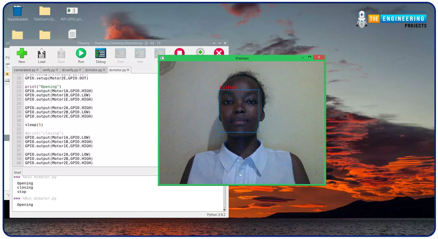
Greeting, and welcome to the next tutorial of our raspberry programming tutorial. In the previous tutorial, we learned how to build a smart attendance system using an RFID card reader, which we used to sign in students in attendance in a class. When it comes to building a face-recognition program on a Raspberry Pi, this tutorial will show you how. Two Python programs will be used in the lesson, one of which is a Training program that analyzes a collection of photographs of a certain individual and generates a dataset. (YML File). The Recognizer application uses the YML script to detect a face and afterward utters the person's name when the face is detected.

Where To Buy?
No.ComponentsDistributorLink To Buy
1BreadboardAmazonBuy Now
2DC MotorAmazonBuy Now
3Jumper WiresAmazonBuy Now
4Raspberry Pi 4AmazonBuy Now

Components

  • Raspberry Pi
  • Breadboard
  • L293 or SN755410 motor driver chip
  • Jumper wires
  • DC motor
  • 5v power supply

A growing number of us already use face recognition software without realizing it. Facial recognition is used in several applications, from basic Fb Tag suggestions to advanced security screening surveillance. Chinese schools employ facial recognition to track students' adherence and behaviour for the first time. Retail stores use face recognition to classify their clients and identify those who have a history of crime. There's no denying that this tech will be all over soon, especially with so many other developments in the works.

How does facial recognition work?

When it comes to facial recognition, biometric authentication goes well beyond simply being able to identify human faces in images or videos. An additional step is taken to identify the person's identity. A facial recognition software compares an image of a person's face to a database to see if the features match another person's. Since facial expressions and hair do not affect the technology's ability to identify matches, it has been built to do so.

How can face recognition be used when it comes to smart security systems?

The first thing you should do if you want to make your home "smart" is to focus on security. Your most prized possessions are housed at this location, and protecting them is a must. You can monitor your home security status from your computer or smartphone thanks to a smart security system when you're outdoors.

Installing a system that is not wireless in your house and signing you up for professional monitoring was traditionally done by a security company. The plot has been rewritten. When setting up a smart home system, you can even do it yourself. In addition, your smart smartphone acts as a professional monitor, providing you with real-time information and notifications.

Face recognition is the ability of a smart camera in your house to identify a person based on their face. Consequently, you will have to inform the algorithm what face goes with what name for face recognition to operate. Facial detection in security systems necessitates the creation of user accounts for family members, acquaintances, and others you want to be identified by the system. Your doors or the inside of your house will be alerted when they arrive.

Face-recognition technology allows you to create specific warning conditions. For example, you can configure a camera to inform you when an intruder enters your home with a face the camera doesn't recognize.

Astonishing advancements in smart tech have been made in recent years. Companies are increasingly offering automatic locks with face recognition. You may open your doors just by smiling at a face recognition system door lock. You could, however, use a passcode or a real key to open and close the smart door. You may also configure your smart house lock to email you an emergency warning if someone on the blacklist tries to unlock your smart security door.

How to install OpenCV for Raspberry Pi 4.

OpenCV, as previously stated, will be used to identify and recognize faces. So, before continuing, let's set up the OpenCV library. Your Pi 4 needs a 2A power adapter and an HDMI cable because we won't be able to access the Pi's screen through SSH. The OpenCV documentation is a good place to learn how image processing works, but I'm not going to go into it here.

Installing OpenCV using pip

pip is well-known for making it simple to add new libraries to the python language. In addition, there is a technique to install OpenCV on a Raspberry Pi via PIP, but it didn't work for me. We can't obtain complete control of the OpenCV library when using pip to install OpenCV; however, this might be worth a go if time is of the essence.

Ensure pip is set up on your Raspberry Pi. Then, one by one, execute the lines of code listed below into your terminal.

sudo apt-get install libhdf5-dev libhdf5-serial-dev

sudo apt-get install libqtwebkit4 libqt4-test

sudo pip install opencv-contrib-python?

How OpenCV Recognizes Face

Facial recognition and face detection are not the same things, and this must be clarified before we proceed. When simply a user's face is detected using Face detection, the program has no clue who that person is. Only the face will be detected in facial recognition software, but the program will also recognize it. At this point, it's pretty evident that facial detection comes before facial recognition. To explain how OpenCV recognizes a person or other objects, I will have to go into detail.

Essentially, a webcam feed is like a long series continuously updating still photos. And every image is nothing more than a jumble of pixels with varying values arranged in a specific order. So, how does a computer software identify a face among all of these random pixels? Trying to describe the underlying techniques is outside the scope of this post, but since we're utilizing the OpenCV library, facial recognition is a straightforward process that doesn't necessitate a deeper understanding of the underlying principles.

Using Cascade Classifiers for Face Detection

We can only recognize a person if we can see it. Detection of an item, including a face, Classifiers are a feature of OpenCV. They are pre-trained datasets that may be utilized to recognize a certain item, such as a face. Classifiers may also detect additional objects, such as the mouth, the eyebrows, the number plate of a vehicle, and smiles.

Alternatively, OpenCV allows you to design your custom Classifier for detecting any objects in images by retraining the cascade classifier. For the sake of this tutorial, we'll be using the classifier named "haarcascade_frontalface_default.xml" to identify faces from the camera. We'll learn more about image classifiers and how to apply them in code in the following sections.

Setup the raspberry pi camera

For the face training and detection, we only need the pi camera, and to install this, insert the raspberry pi camera in the pi camera slot as shown below. Then go to your terminal, open the configuration window using "sudo raspi-config", and press enter. Navigate to the interface options and activate the pi camera module. Accept the changes and finish the setup. Then reboot your RPi.

How to Setup the Necessary Software

First, ensure pip is set up, and then install the following packages using it.

Install dlib: Dlib is a set of libraries for building ML and data analysis programs in the real world. To get dlib up and running, type the following command into your terminal window.

Pip install dlib

If everything goes according to plan, you should see something similar after running this command.

Install pillow: The Python Image Library, generally known as PIL, is a tool for opening, manipulating, and saving images in various formats. The following command will set up PIL for you.

pip install pillow

You should receive the message below once this app has been installed.

Install face_recognition: The face recognition package is often the most straightforward tool for detecting and manipulating human faces. Face recognition will be made easier with the help of this library. Installing this library is as simple as running the provided code.

Pip install face_recognition –no –cache-dir

If all goes well, you should see something similar to the one shown below after the installed software. Due to its size, I used the "—no –cache-dir" command-line option to configure the package without keeping any of its cache files.

Face Recognition Folders

A script named "haarcascade_frontalface_default.xml" is for detecting faces using a Classifier. It will also build a "face-trainner.yml" file using the training script based on the photos found in the face images directory.

Start the face images folder with a collection of face images.

The face images folder indicated above should contain subdirectories with the names of each person to be identified and several sample photographs of them. Esther and x have been identified for this tutorial. As a result, I've just generated the two sub-directories shown below, each containing a single image.

You must rename the directory and replace the photographs with the names of the people you are identifying. It appears that a minimum of five images for each individual is optimal. However, the more participants, the slower the software will run.

Face trainer program

Face Trainer.py is a Python software that may be used to train a new face. The purpose of the software is to access the face photographs folder and scan for faces. As soon as it detects a face, it crops it, turns it to grayscale, and saves it in a file named face-trainner.yml using the face recognition package we had previously loaded. The information in this script can be used to identify the faces later. In addition to the whole Trainer program provided at the conclusion, we'll go over some more critical lines.

The first step is to import the necessary modules. The cv2 package is utilized to process photos. The NumPy library can be used for image conversion, the operating system package is used for directory navigation, and PIL will be used to process photos.

import cv2

import numpy as np

import os

from PIL import Image

Ensure that the XML file in question is located in the project directory to avoid encountering an issue. The LBPH Facial recognizer is then constructed using the recognizer parameter.

face_cascade = cv2.CascadeClassifier('haarcascade_frontalface_default.xml')

recognizer = cv2.createLBPHFaceRecognizer()

Face_Images = os.path.join(os.getcwd(), "Face_Images")

In order to open all of the files ending in.jpg,.jpg, or .png within every subfolder in the face images folder, we must traverse the tree with for loops. In a variable named path, we record the path to every image, and in a variable named person name, we store the file location name (the name of the user who uploaded the images).

For root, dirs, files in os.walk(Face_Images):

for file in files: #check every directory in it

if file.endswith("jpeg") or file.endswith("jpg") or file.endswith("png"):

path = os.path.join(root, file)

person_name = os.path.basename(root)

As a result, in case the name of the person changes, we increase a variable named Face_ID that will allow us to have a unique Face_ID for each individual.

if pev_person_name!=person_name:

Face_ID=Face_ID+1 #If yes increment the ID count

pev_person_name = person_name

Because the BGR values may be ignored, grayscale photos are simpler for OpenCV to deal with than colourful ones. We transform the data to grayscale and afterwards lower the image size by 50% so that all the pictures are the same size. To avoid having your face cut out, place it in the centre of the photo. To get a numerical number for these photos, transform them into NumPy arrays. Afterwards, a classifier identifies a face in a photo and saves the results in variable named faces.

Gery_Image = Image.open(path).convert("L")

Crop_Image = Gery_Image.resize( (550,550) , Image.ANTIALIAS)

Final_Image = np.array(Crop_Image, "uint8")

faces = face_cascade.detectMultiScale(Final_Image, scaleFactor=1.5, minNeighbors=5)

Our Area of Attention will be the portion of the image where the face may be found after being cropped. It will be utilized to train the face-recognition system in the ROI area. Every area of attention face must be appended to a variable named x train. We then feed the recognizer with our training data using the area of attention values and Face ID data. The information gathered will be archived.

for (x,y,w,h) in faces:

roi = Final_Image[y:y+h, x:x+w]

x_train.append(roi)

y_ID.append(Face_ID)


recognizer.train(x_train, np.array(y_ID))

recognizer.save("face-trainner.yml")

You'll notice that the face-trainner.yml script is modified whenever you run this program. If you make any modifications to the photographs in the Face Images folder, ensure to recompile this code. Debugging purposes include printing out the Face ID, name of the path, name of a person, and NumPy arrays.

Face recognition program

We can begin using our trained data to identify people now that it has been prepared. We'll use a USB webcam or pi camera to feed video into the Face recognizer application, turning it into an image. Once we've found the faces in those images, we'll find similarities to all of our previously developed Face IDs. Finally, we output the identified person’s name in boxes around their face. Afterwards, the whole program is presented, and the explanation is below.

Import the required module from the training program and use the classifier because we need to do more facial detection in this program.

import cv2

import numpy as np

import os

from time import sleep

from PIL import Image

face_cascade = cv2.CascadeClassifier('haarcascade_frontalface_default.xml')

recognizer = cv2.createLBPHFaceRecognizer()

The people listed in the folder should be entered in the variable named labels. Insist on performing each step in the same order. It is "Esther" and "Unknown" in my situation.

labels = ["Esther", "Unknown"]

We need the trainer file to detect faces, so we import it into our software.

recognizer.load("face-trainner.yml")

The camera provides the video stream. It's possible to access any second pi camera by replacing 0 with 1.

cap = cv2.VideoCapture(0)

In the next step, we separate the footage into images and transform it into grayscale, and afterwards, we search for a face in the photo. To save the area of attention grey image, we must first detect the face and then crop the image to remove them.

ret, img = cap.read()

gray = cv2.cvtColor(img, cv2.COLOR_BGR2GRAY)

faces = face_cascade.detectMultiScale(gray, scaleFactor=1.5, minNeighbors=5)

for (x, y, w, h) in faces:

roi_gray = gray[y:y+h, x:x+w]

id_, conf = recognizer.predict(roi_gray)

It informs us how sure the program is in its ability to identify the person. We write the code below to get the person's name based on their Identification number. A square should be drawn around the user's head, written outside their name.

if conf>=80:

font = cv2.FONT_HERSHEY_SIMPLEX

name = labels[id_]

cv2.putText(img, name, (x,y), font, 1, (0,0,255), 2)

cv2.rectangle(img,(x,y),(x+w,y+h),(0,0,255),2)

We must playback and afterwards break the video stream we just evaluated, which is done by pressing a wait key.

cv2.imshow('Preview',img)

if cv2.waitKey(20) & 0xFF == ord('q'):

break

While running this application, ensure the Raspberry is linked to a display via HDMI. A display with your video stream and the name will appear when you open the application. There will be a box around the face identified in the video feed, and if your software recognizes the face, it displays that person’s name. As evidenced by the image below, we've trained our software to identify my face, which shows the recognition process in action.

The face recognition code

import cv2

import numpy as np

import os

from PIL import Image

labels = ["Esther", "Unknown"]

face_cascade = cv2.CascadeClassifier('haarcascade_frontalface_default.xml')

recognizer = cv2.createLBPHFaceRecognizer()

recognizer.load("face-trainner.yml")

cap = cv2.VideoCapture(0)

while(True):

ret, img = cap.read()

gray = cv2.cvtColor(img, cv2.COLOR_BGR2GRAY)

faces = face_cascade.detectMultiScale(gray, scaleFactor=1.5, minNeighbors=5) #Recog. faces

for (x, y, w, h) in faces:

roi_gray = gray[y:y+h, x:x+w]

id_, conf = recognizer.predict(roi_gray)

if conf>=80:

font = cv2.FONT_HERSHEY_SIMPLEX

name = labels[id_]

cv2.putText(img, name, (x,y), font, 1, (0,0,255), 2)

cv2.rectangle(img,(x,y),(x+w,y+h),(0,255,0),2)

cv2.imshow('Preview',img)

if cv2.waitKey(20) & 0xFF == ord('q'):

break

cap.release()

cv2.destroyAllWindows()

Face detection code

import cv2

import numpy as np

import os

from PIL import Image

face_cascade = cv2.CascadeClassifier('haarcascade_frontalface_default.xml')

recognizer = cv2.createLBPHFaceRecognizer()


Face_ID = -1

pev_person_name = ""

y_ID = []

x_train = []

Face_Images = os.path.join(os.getcwd(), "Face_Images")

print (Face_Images)

for root, dirs, files in os.walk(Face_Images):

for file in files:

if file.endswith("jpeg") or file.endswith("jpg") or file.endswith("png"):

path = os.path.join(root, file)

person_name = os.path.basename(root)

print(path, person_name)

if pev_person_name!=person_name:

Face_ID=Face_ID+1

pev_person_name = person_name

Gery_Image = Image.open(path).convert("L")

Crop_Image = Gery_Image.resize( (550,550) , Image.ANTIALIAS)

Final_Image = np.array(Crop_Image, "uint8")

faces = face_cascade.detectMultiScale(Final_Image, scaleFactor=1.5, minNeighbors=5)

print (Face_ID,faces)

for (x,y,w,h) in faces:

roi = Final_Image[y:y+h, x:x+w]

x_train.append(roi)

y_ID.append(Face_ID)

recognizer.train(x_train, np.array(y_ID))

recognizer.save("face-trainner.yml")

DC motor circuit

Since the "How to operate DC motor in Rpi 4" guide has covered the basics of controlling a DC motor, I won't provide much detail here. Please read this topic if you haven't already. Check all the wiring before using the batteries in your circuit, as outlined in the image above. Everything must be in place before connecting your breadboard's power lines to the battery wires.

Testing

To activate the motors, open the terminal because you'll use the Python code-writing program called Nano in this location. For those of you who aren't familiar with the command-line text editor known as Nano, I'll show you how to use some of its commands as we go.

This code will activate the motor for two seconds, so try it out.

import RPi.GPIO as GPIO

from time import sleep

GPIO.setmode(GPIO.BOARD)

Motor1A = 16

Motor1B = 18

Motor1E = 22

GPIO.setup(Motor1A,GPIO.OUT)

GPIO.setup(Motor1B,GPIO.OUT)

GPIO.setup(Motor1E,GPIO.OUT)

print "Turning motor on"

GPIO.output(Motor1A,GPIO.HIGH)

GPIO.output(Motor1B,GPIO.LOW)

GPIO.output(Motor1E,GPIO.HIGH)

sleep(2)

print "Stopping motor"

GPIO.output(Motor1E,GPIO.LOW)

GPIO.cleanup()

The very first two lines of code tell Python whatever the program needs.

The RPi.GPIO package is what the first line is looking for. The RPi GPIO pins are controlled by this module, which takes care of all the grunt work.

It is necessary to delay the script for a few seconds to provide the package time to operate, therefore leaving a motor to run for a while.

The method set mode is used to leverage the RPi's board numbers. We'll tell Python that the pins 16 through 22 correspond to the motors.

Pin A is used to steer the L293D in one way, and pin B is used to direct it in the opposite direction. You can turn on the motor using an Enable pin, referred to as E, inside the test file.

Finally, use GPIO.OUT to inform the RPi that all these are outputs.

The RPi is ready to turn the motor after the software is set up. After a 2-second pause, some pins will be turned on and subsequently turned off, as seen in the code.

Save and quit by hitting CTRL-X, and a confirmation notice appears at the bottom. To acknowledge, tap Y and Return. You can now run the program in the terminal and watch as the motor begins to spin up.

sudo python motor.py

If the motor doesn't move, check the cabling or power supply. The debug process might be a pain, but it's an important phase in learning new things!

Now turn in the other direction.

I'll teach you how to reverse a motor's rotation to spin in the opposite direction.

There's no need to touch the wiring at this point; it's all Python. Create a new script called motorback.py to accomplish this. Using Nano, type the command:

./script

Please type in the given program:

import RPi.GPIO as GPIO

from time import sleep

GPIO.setmode(GPIO.BOARD)

Motor1A = 16

Motor1B = 18

Motor1E = 22

GPIO.setup(Motor1A,GPIO.OUT)

GPIO.setup(Motor1B,GPIO.OUT)

GPIO.setup(Motor1E,GPIO.OUT)

print "Going forwards"

GPIO.output(Motor1A,GPIO.HIGH)

GPIO.output(Motor1B,GPIO.LOW)

GPIO.output(Motor1E,GPIO.HIGH)

sleep(2)

print "Going backwards"

GPIO.output(Motor1A,GPIO.LOW)

GPIO.output(Motor1B,GPIO.HIGH)

GPIO.output(Motor1E,GPIO.HIGH)

sleep(2)

print "Now stop"

GPIO.output(Motor1E,GPIO.LOW)

GPIO.cleanup()

Save by pressing CTRL, then X, then Y, and finally Enter key.

For reverse compatibility, we've set Motor1A low in the script.

Programmers use the terms "high" and "low" to denote the state of being on or off, respectively.

Motor1E will be turned off to halt the motor.

Irrespective of what A is doing; the motor can be turned on or off using the Enable switch.

Take a peek at the Truth Table to understand better what's going on.

When Enabled, only two states allow the motor to move; A or B is high, and not both high at the same time.

Putting it all together

At this point, we have designed our face detection system and the dc motor control circuit; now, we will put the two systems to work together. When the user is verified, the dc motor should run to open the cd rom drive and close after a few seconds.

In our verify code, we will copy the code below to spin the motor in one direction “open the door” when the user is verified. We will also increase the time to 5 seconds to simulate the door's time to open for the user to get through. This also allows the motor to spin long enough to open and close the cd room completely. I would also recommend putting a stopper on the cd room door so that it doesn't close all the war and get stuck.

if conf>=80:

font = cv2.FONT_HERSHEY_SIMPLEX

name = labels[id_] #Get the name from the List using ID number

cv2.putText(img, name, (x,y), font, 1, (0,0,255), 2)

#place our motor code here

GPIO.setmode(GPIO.BOARD)

Motor1A = 16

Motor1B = 18

Motor1E = 22


GPIO.setup(Motor1A,GPIO.OUT)

GPIO.setup(Motor1B,GPIO.OUT)

GPIO.setup(Motor1E,GPIO.OUT)

Print("Openning")

GPIO.output(Motor1A,GPIO.HIGH)

GPIO.output(Motor1B,GPIO.LOW)

GPIO.output(Motor1E,GPIO.HIGH)

sleep(5)

print("Closing")

GPIO.output(Motor1A,GPIO.LOW)

GPIO.output(Motor1B,GPIO.HIGH)

GPIO.output(Motor1E,GPIO.HIGH)

sleep(5)

print("stop")

GPIO.output(Motor1E,GPIO.LOW)

GPIO.cleanup()

cv2.rectangle(img,(x,y),(x+w,y+h),(0,255,0),2)

Output

The advantages of face recognition over alternative biometric verification methods for home security

An individual's biometric identity can be verified by looking at various physical and behavioural characteristics, such as a person's fingerprint, keystrokes, facial characteristics, and voice. Face recognition seems to be the winner because of the precision, simplicity, and lack of contact detection.

Face-recognition technology will continue and will get better over time. The tale has evolved, and your alternatives have grown due to smart tech.

What are the advantages of employing Facial Recognition when it comes to smart home security?

Using an RPi as a surveillance system means you can take it with you and use it wherever you need it.

  1. High accuracy rate

For the most part, the face-recognition software employed in security systems can reliably assess whether or not the individual attempting entry matches your record of those authorized to enter. On the other hand, certain computer programs are more precise when it comes to identifying faces from diverse angles or different countries.

Concerned users may be relieved to learn that some programs have the option of setting custom confidence criteria, which can significantly minimize the likelihood of the system giving false positives. Alternatively, 2-factor authentication can be used to secure your account.

  1. Automation

When your smart security system discovers a match between a user and the list of persons you've given access to, it will instantly let them in. Answering the doorbell or allowing entry isn't necessary.

  1. Smart integration

Face recognition solutions can be readily integrated into existing systems using an API.

Cons of Facial Recognition

  1. Privacy of individuals and society as a whole is more at risk

A major drawback of face recognition technology is that it puts people's privacy at risk. Having one's face collected and stored in an unidentified database does not sit well with the average person.

Confidentiality is so important that several towns have prohibited law enforcement from using real-time face recognition monitoring. Rather than using live face recognition software, authorities can use records from privately-held security cameras in certain situations.

  1. can infringe on one's liberties

Having your face captured and stored by face recognition software might make you feel monitored and assessed for your actions. It is a form of criminal profiling since the police can use face recognition to put everybody in their databases via a virtual crime lineup.

  1. It's possible to deceive modern technology.

Face recognition technology can be affected by various other elements, including camera angle, illumination, and other aspects of a picture or video. Facial recognition software can be fooled by those who do disguises or alter their appearance.

Conclusion

This article walked us through creating a complete Smart Security System using a facial recognition program from the ground up. Our model can now recognize faces with the help of OpenCV image manipulation techniques. There are several ways to further your knowledge of supervised machine learning programming with raspberry pi 4, including adding an alarm to ring whenever an individual's face is not recognized or creating a database of known faces to act like a CCTV surveillance system. We'll design a security system with a motion detector and an alarm in the next session.

Smart Attendance System using RFID with Raspberry Pi 4

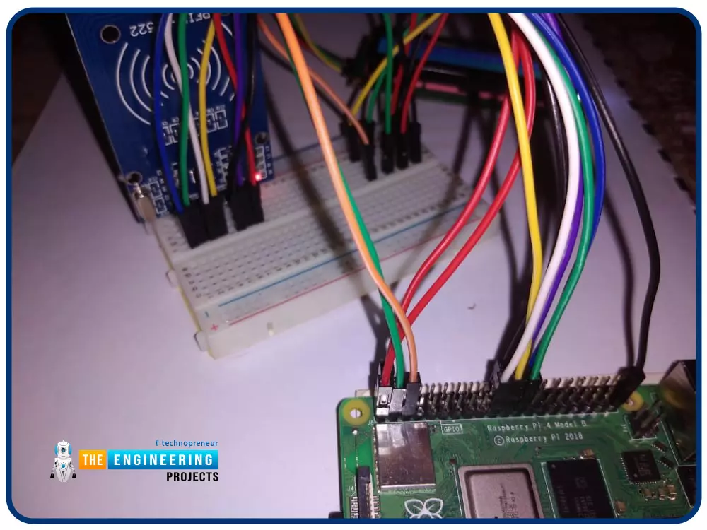
Greetings! This is the complete project of our Raspberry Pi 4 tutorials. In our previous tutorial, we learned to set up our raspberry pi as a virtual private network server. In this tutorial, we will design a smart attendance system using an RFID card reader, which we will use to sign in students in attendance in a class.

First, we will design a database for our website, then we will design the RFID circuit for scanning the student cards and displaying present students on the webpage, and finally, we will design the website that we will use to display the attendees of a class.

Where To Buy?
No.ComponentsDistributorLink To Buy
1BreadboardAmazonBuy Now
2Jumper WiresAmazonBuy Now
3LCD 16x2AmazonBuy Now
4LCD 16x2AmazonBuy Now
5Raspberry Pi 4AmazonBuy Now

Components

  • RFID card kit
  • Breadboard
  • Jumper wires
  • Raspberry pi 4
  • I2C LCD screen

Design a database in MySQL server

Additionally, the Database server offers a DBMS that can be queried and connected to and can integrate with a wide range of platforms. High-volume production environments are no problem for this software. The server's connection, speed, and encryption make it a good choice for accessing the database.

There are clients and servers for MySQL. This system contains a SQL server with many threads that support a wide range of back ends, utility programs, and application programming interfaces.

We'll walk through the process of installing MySQL on the RPi in this part. The RFID kit's database resides on this server, and we'll utilize it to store the system's signed users.

There are a few steps before we can begin installing MySQL on a Raspberry Pi. There are two ways to accomplish this.

sudo apt update

sudo apt upgrade

Installing the server software is the next step.

Here's how to get MySQL running on the RPi using the command below:

sudo apt install MariaDB-server

Having installed MySQL on the Raspberry Pi, we'll need to protect it by creating a passcode for the "root" account.

If you don't specify a password for your MySQL server, you can access it without authentication.

Using this command, you may begin safeguarding MySQL.

sudo mysql_secure_installation

Follow the on-screen instructions to set a passcode for the root account and safeguard your MySQL database.

To ensure a more secured installation, select "Y" for all yes/no questions.

Remove elements that make it easy for anyone to access the database.

We may need that password to access the server and set up the database and user for applications like PHPMyAdmin.

For now, you can use this command if you wish to access the Rpi's MySQL server and begin making database modifications.

sudo MySQL –u root -p

To access MySQL, you'll need to enter the root user's password, which you created in Step 3.

Note: Typing text will not appear while typing, as it does in typical Linux password prompts.

Create, edit, and remove databases with MYSQL commands now available. Additionally, you can create, edit, and delete users from inside this interface and provide them access to various databases.

After typing "quit;" into MySQL's user interface, you can exit the command line by pressing the ESC key.

Pressing CTRL + D will also exit the MYSQL command line.

You may proceed to the next step now that you've successfully installed MySQL. In the next few sections, we'll discuss how to get the most out of our database.

Creating database and user

The command prompt program MySQL must be restarted before we can proceed with creating a username and database on the RPi.

The MySQL command prompt can be accessed by typing the following command. After creating the "root" user, you will be asked for the password.

To get things started, run the command to create a MySQL database.

The code to create a database is "CREATE DATABASE", and then the name we like to give it.

This database would be referred to as "rfidcardsdb" in this example.

To get started, we'll need to create a MySQL user. The command below can be used to create this new user.

"rfidreader" and "password" will be the username and password for this example. Take care to change these when making your own.

create user “rfidreader" @localhost identified by "password."

We can now offer the user full access to the database after it has been built.

Thanks to this command, " "rfidreader" will now have access to all tables in our "rfidcardsdb" database.

grant all on rfidcardsdb.* to "rfidreader" identified by "password."

We have to flush the permission table to complete our database and user set up one last time. You cannot grant access to the database without flushing your privilege table.

The command below can be used to accomplish this.

Now we have our database configured, and now the next step is to set up our RFID circuit and begin authenticating users. Enter the “Exit” command to close the database configuration process.

The RFID card circuit

An RFID reader reads the tag's data when a Rfid card is attached to a certain object. An RFID tag communicates with a reader via radio waves.

In theory, RFID is comparable to bar codes in that it uses radio frequency identification. While a reader's line of sight to the RFID tag is preferable, it is not required to be directly scanned by the reader. You can't read an RFID tag that is more than three feet away from the reader. To quickly scan a large number of objects, the RFID tech is used, and this makes it possible to identify a specific product rapidly and effortlessly, even if it is sandwiched between several other things.

HOW RFID CARD READERS AND WRITERS WORK

There are major parts to Cards and tags: an IC that holds the unique identifier value and a copper wire that serves as the antenna:

Another coil of copper wire can be found inside the RFID card reader. When current passes through this coil, it generates a magnetic field. The magnetic flux from the reader creates a current within the wire coil whenever the card is swiped near the reader. This amount of current can power the inbuilt IC of the Card. The reader then reads the card's unique identifying number. For further processing, the card reader transmits the card's unique identification number to the controller or CPU, such as the Raspberry Pi.

RFID card reader circuit

Connect the reader to the Raspberry the following way:

use the code spi bcm2835 to see if it is displayed in the terminal.

lsmod | grep spi

SPI must be enabled in the setup for spi bcm2835 to appear (see above). Make sure that RPi is running the most recent software.

Make use of the python module.

sudo apt-get install python

The RFID RC522 can be interacted with using the Library SPI Py, found on your RPi.

cd ~

git clone https://github.com/lthiery/SPI-Py.git

cd ~/SPI-Py

sudo python setup.py install

cd ~

git clone https://github.com/pimylifeup/MFRC522-python.git

To test if the system is functioning correctly, let's write a small program:

cd ~/

sudo nano test.py

now copy the following the code into the editor

import RPi.GPIO as GPIO

import sys

sys.path.append('/home/pi/MFRC522-python')

from mfrc522 import SimpleMFRC522

reader = SimpleMFRC522()

print("Hold a tag near the reader")

try:

id, text = reader.read()

print(id)

print(text)

finally:

GPIO.cleanup()

Register card

Here we will write a short python code to register users whenever they swipe a new card on the RFID card reader. First, create a file named addcard.py.

copy the following code.

import pymysql

import cv2

from mfrc522 import SimpleMFRC522

import RPi.GPIO as GPIO

import drivers

display = drivers.Lcd()

display.lcd_display_string('Scan your', 1)

display.lcd_display_string('card', 2)

reader = SimpleMFRC522()

reader = SimpleMFRC522()

id, text = reader.read()

display = drivers.Lcd()

display.lcd_display_string('Type your name', 1)

display.lcd_display_string('in the terminal', 2)

user_id = input("user name?")

# put serial_no uppercase just in case

serial_no = '{}'.format(id)

# open an sql session

sql_con = pymysql.connect(host='localhost', user='rfidreader', passwd='password', db='rfidcardsdb')

sqlcursor = sql_con.cursor()

# first thing is to check if the card exist

sql_request = 'SELECT card_id,user_id,serial_no,valid FROM cardtbl WHERE serial_no = "' + serial_no + '"'

count = sqlcursor.execute(sql_request)

if count > 0:

print("Error! RFID card {} already in database".format(serial_no))

display = drivers.Lcd()

display.lcd_display_string('The card is', 1)

display.lcd_display_string('already registered', 2)

T = sqlcursor.fetchone()

print(T)

else:

sql_insert = 'INSERT INTO cardtbl (serial_no,user_id,valid) ' + \

'values("{}","{}","1")'.format(serial_no, user_id)

count = sqlcursor.execute(sql_insert)

if count > 0:

sql_con.commit()

# let's check it just in case

count = sqlcursor.execute(sql_request)

if count > 0:

print("RFID card {} inserted to database".format(serial_no))

T = sqlcursor.fetchone()

print(T)

display = drivers.Lcd()

display.lcd_display_string('Congratulations', 1)

display.lcd_display_string('You are registered', 2)

GPIO.cleanup()

The program starts by asking the user to scan the card.

Then it connects to the database using the pymysql.connect function.

If we enter our name successfully, the program inserts our details in the database, and a congratulations message is displayed to show that we are registered.

Creating the main system

Using the LCD command library, you can:

  1. Install git

sudo apt install git

  1. Download and install the repo on your Raspberry Pi.

cd /home/pi/

git clone https://github.com/the-raspberry-pi-guy/lcd.git

cd lcd/

  1. Then begin installation with the following

sudo ./install.sh

After installation is complete, try running one of the program files

cd /home/pi/lcd/

Next, we will install the mfrc522 library, which the RFID card reader uses. This will enable us to read the card number for authentication. We will use:

Pip install mfrc522

Next, we will import the RPI.GPIO library enables us to utilize the raspberry pi pins to power the RFID card and the LCD screen.

Import RPi.GPIO

We will also import the drivers for our LCD screen. The LCD screen used here is the I2C 16 * 2 LCD.

Import drivers

Then we will import DateTime for logging the time the user has swiped the card into the system.

Import DateTime

In order to read the card using the rfid card, we will use the following code:

reader = SimpleMFRC522()

display = drivers.Lcd()

display.lcd_display_string('Hello Please', 1)

display.lcd_display_string('Scan Your ID', 2)

try:

id, text = reader.read()

print(id)

display.lcd_clear()

finally:

GPIO.cleanup()

The LCD is divided into two rows, 1 and 2. To display text in the first row, we use:

Display.lcd_display_string(“string”,1)

And 2 to display in the second row.

After scanning the card, we will connect to the database we created earlier and search whether the scanned card is in the database or not.

If the query is successful, we can display if the card is in the database; if not, we can proceed, then the user needs to register the card.

If the user is registered, the system saves the logs, the username and the time the card was swapped in a text file located in the/var/www/html root directory of the apache server.

Note that you will need to be a superuser to create the data.txt file in the apache root directory. For this, we will use the following command in the Html folder:

Sudo touch data.txt

Then we will have to change the access privileges of this data.txt file to use the program to write the log data. For this, we will use the following code:

Sudo chmod 777 –R data.txt

The next step will be to display this data on a webpage to simulate an online attendance register. The code for the RFID card can be found below.

#! /usr/bin/env python

# Import necessary libraries for communication and display use

import RPi.GPIO as GPIO

from mfrc522 import SimpleMFRC522

import pymysql

import drivers

import os

import numpy as np

import datetime

# read the card using the rfid card

reader = SimpleMFRC522()

display = drivers.Lcd()

display.lcd_display_string('Hello Please', 1)

display.lcd_display_string('Scan Your ID', 2)

try:

id, text = reader.read()

print(id)

display.lcd_clear()

# Load the driver and set it to "display"

# If you use something from the driver library use the "display." prefix first

try:

sql_con = pymysql.connect(host='localhost', user='rfidreader', passwd='password', db='rfidcardsdb')

sqlcursor = sql_con.cursor()

# first thing is to check if the card exist

cardnumber = '{}'.format(id)

sql_request = 'SELECT user_id FROM cardtbl WHERE serial_no = "' + cardnumber + '"'

now = datetime.datetime.now()

print("Current date and time: ")

print(str(now))

count = sqlcursor.execute(sql_request)

if count > 0:

print("already in database")

T = sqlcursor.fetchone()

print(T)

for i in T:

print(i)

file = open("/var/www/html/data.txt","a")

file.write(i +" Logged at "+ str(now) + "\n")

file.close()

display.lcd_display_string(i, 1)

display.lcd_display_string('Logged In', 2)

else:

display.lcd_clear()

display.lcd_display_string(“Please register”, 1)

display.lcd_display_string(cardnumber,2)

except KeyboardInterrupt:

# If there is a KeyboardInterrupt (when you press ctrl+c), exit the program and cleanup

print("Cleaning up!")

display.lcd_clear()

finally:

GPIO.cleanup()

Building the website

Now we are going to design a simple website with Html that we are going to display the information of the attending students of a class, and to do this, we will have to install a local server in our raspberry pi.

Installing Apache Web Server

Web, database, and mail servers all run on various server software. Each of these programs can access and utilize files located on a physical server.

A web server's main responsibility is to provide internet users access to various websites. It serves as a bridge between a server and a client machine to accomplish this. Each time a user makes a request, it retrieves data from the server and posts it to the web.

A web server's largest issue is to simultaneously serve many web users, each of whom requests a separate page.

For internet users, convert them to Html pages and offer them in the browser. Whenever you hear the term "webserver," consider the device in charge of ensuring successful communication in a network of computers.

How Does Apache Work?

Among its responsibilities is establishing a link between a server and a client's web browser (such as Chrome to send and receive data (client-server structure). As a result, the Apache software can be used on any platform, from Microsoft to Unix.

Visitors to your website, such as those who wish to view your homepage or "About Us" page, request files from your server via their browser, and Apache returns the required files in a response (text, images, etc.).

Using HTTP, the client and server exchange data with the Apache webserver, ensuring that the connection is safe and stable.

Because of its open-source foundation, Apache promotes a great deal of customization. As a result, web developers and end-users can customize the source code to fit the needs of their respective websites.

Additional server-side functionality can be enabled or disabled using Apache's numerous modules. Encryption, password authentication, and other capabilities are all available as Apache modules.

Step 1

To begin, use the following code to upgrade the Pi package list.

sudo apt-get update

sudo apt-get upgrade

Step 2

After that, set up the Apache2 package.

sudo apt install apache2 -y

That concludes our discussion. You can get your Raspberry Pi configured with a server in just two easy steps.

Type the code below to see if the server is up and functioning.

sudo service apache2 status

You can now verify that Apache is operating by entering your Raspberry Pi's IP address into an internet browser and seeing a simple page like this.

Use the following command in the console of your Raspberry Pi to discover your IP.

hostname-i

Only your home network and not the internet can access the server. You'll need to configure your router's port forwarding to allow this server to be accessed from any location. Our blog will not be discussing this topic.

Setting up HTML page for editing.

The standard web page on the Raspberry Pi, as depicted above, is nothing more than an HTML file. First, we will generate our first Html document and develop a website.

Step 1

Let's start by locating the Html document on the Raspbian system. You can do this by typing the following code in the command line.

cd /var/www/html

Step 2

To see a complete listing of the items in this folder, run the following command.

ls -al

The root account possesses the index.html file; therefore, you'll see every file in the folder.

As a result, to make changes to this file, you must first change the file's ownership to your own. The username "pi" is indeed the default for the Raspberry Pi.

sudo chown pi: index.html

To view the changes you've made, all you have to do is reload your browser after saving the file.

Building your first HTML page

Here, we'll begin to teach you the fundamentals of HTML.

To begin a new page, edit the index.html file and remove everything inside it using the command below.

sudo nano index.html

Alternatively, we can use a code editor to open the index.html file and edit it. We will use VS code editor that you can easily install in raspberry pi using the preferences then recommended software button.

HTML Tags

You must first learn about HTML tags, which are a fundamental part of HTML. A web page's content can be formatted in various ways by using tags.

There are often two tags used for this purpose: the opening and closing tags. The material inside these tags behaves according to what these tags say.

The p> tag, for example, is used to add paragraphs of text to the website.

<p>The engineering projects</p>

Web pages can be made more user-friendly by using buttons, which can be activated anytime a user clicks on them.

<button>Manual Refresh</button>

<button>Sort By First Name</button>

<button>Sort By last Name</button>

The basic format of an HTML document

A typical HTML document is organized as follows:

Let us create the page that we will use in this project.

<html>

<head>

</head>

<body>

<div id="pageDiv">

<p> The engineering projects</p>

<button type="button" id="refreshNames">Manual Refresh</button><br/>

<button type="button" id="firstSort">Sort By First Name</button><br/>

<button type="button" id="lastSort">Sort By Last Name</button>

<div id="namesFromFile">

</div>

</div>

</body>

</html>

<!DOCTYPE html>: HTML documents are identified by this tag. This does not necessitate the use of a closing tag.

<html>: This tag ensures that the material inside will meet all of the requirements for HTML. There is a /html> tag at the end of this.

</head>: It contains data about the website, but when you view it in a browser, you won't be able to see anything.

A metadata tag in the head tag can be used to set default character encoding in your website, for instance. This has a /head> tag at the end of it.

<head>

<meta charset="utf-8">

</head>

Also, you can have a title tag inside the head tag. This tag sets the title of your web page and has a closing </title> tag.

<head>

<meta charset="utf-8">

<title> My website </title>

</head>

<body>: The primary focus of the website page is included within this tag. Everything on a web page is usually contained within body tags once you've opened it. This has a /body> tag at the end of it. Many other tags can be found in this body tag, but we'll focus on the ones you need to get started with your first web page.

We will go ahead and style our webpage using CSS with the lines of codes below;

<head>

<!--

body {

width:100%;

background:#ccc;

color:#000;

text-align:left;

margin:0

;padding:10px

;font:16px/18pxArial;

}

button {

width:160px;

margin:0 0 10px;}

#pageDiv {

width:160px;

margin:20px auto;

padding:20px;

background:#ddd;

color:#000;

}

#namesFromFile {

margin:20px 0 0;

padding:10px;

background:#fff;

color:#000;

border:1px solid #000;

border-radius:10px;

}

-->

</style>

</head>

The style tags is a cascading style sheet syntax that lets developers style the webpages however they prefer.

Adding images to your web page

You can add images to your web page by using the <img> tag. It is also a void element and doesn’t have a closing tag. It takes the following format

<img src="URL of image location">

For example, let’s add an image of the Seeeduino XIAO

<p>The Engineering projects</p>

<img src="https://www.theengineeringprojects.com/wp-content/uploads/2022/04/TEP-Logo.png">

Reload the browser to see the changes

How to display the attendance list on the webpage

This is the last step of this project, and we will implement a program that reads our data.txt file from the apache root directory and display it on the webpage that we designed. Since we already have our webpage up and running, we will use the javascript programming language to implement this function of displaying the log list on the webpage. All changes that we are about to implement will be done in the index.html file; therefore, open it in the visual studio code editor.

Javascript – What is it?

JavaScript is a dynamic computer programming language. It is lightweight and most commonly used as a part of web pages, whose implementations allow client-side scripts to interact with the user and make dynamic pages. It is an interpreted programming language with object-oriented capabilities.

Advantage of javascript

One of the major strengths of JavaScript is that it does not require expensive development tools. You can start with a simple text editor such as Notepad.

How to use javascript with this program

Well, javascript as mentioned earlier is a very easy to use language that simply requires us to put the script tags inside the html tags.

<script> script program </script>

<header>

<script>

Here goes our javascript program

</script>

</header>

The javascript code first opens the data.txt file, then it reads all the contents form that file. Then it uses the xmlHttpRequest function to display the contents on the webpage. The buttons on the webpage activate different functions in the code.For instance manual refresh activates:

function refreshNamesFromFile(){

var namesNode=document.getElementById("namesFromFile");

while(namesNode.firstChild)

{ namesNode.removeChild(namesNode.firstChild);

}

getNameFile();

}

This function reads the content of the data.txt

The sort by buttons activate the sort function to sort the logged users either by first name or last name. The function that gets activated by these buttons is:

function sortByName(e)

{ var i=0, el, sortEl=[], namesNode=document.getElementById("namesFromFile"), sortMethod, evt, evtSrc, oP;

evt=e||event;

evtSrc=evt.target||evt.srcElement;

sortMethod=(evtSrc.id==="firstSort")?"first":"last";

while(el=namesNode.getElementsByTagName("P").item(i++)){

sortEl[i-1]=[el.innerHTML.split(" ")[0],el.innerHTML.split(" ")[1]];

}

sortEl.sort(function(a,b){

var x=a[0].toLowerCase(), y=b[0].toLowerCase(), s=a[1].toLowerCase(), t=b[1].toLowerCase();

if(sortMethod==="first"){

return x<y?-1:x>y?1:s<t?-1:s>t?1:0;

}

else{

return s<t?-1:s>t?1:x<y?-1:x>y?1:0;

}

});

while(namesNode.firstChild){

namesNode.removeChild(namesNode.firstChild);

}

for(i=0;i<sortEl.length;i++){

oP=document.createElement("P");

namesNode.appendChild(oP).appendChild(document.createTextNode(sortEl[i][0]+" "+sortEl[i][1]));

namesNode.appendChild(document.createTextNode("\r\n"));

//insert tests -> for style/format

if(sortEl[i][0]==="John"){

oP.style.color="#f00";

}

if(sortEl[i][0]==="Sue")

{ oP.style.color="#0c0";

oP.style.fontWeight="bold";

}

}

}

Output

With no logged-in users

With one logged in user

With two users logged in

Sort by the first name

Sort by last name

Applications of RFID

Benefits of Smart Attendance System

Automated attendance systems are excessively time-consuming and sophisticated in the current environment. It is possible to strengthen company ethics and work culture by using an effective smart attendance management system. Employees will only have to complete the registration process once, and images get saved in the system's database. The automated attendance system uses a computerized real-time image of a person's face to identify them. The database is updated frequently, and its findings are accurate in a user interactive state because each employee's presence is recorded.

Smart attendance systems have several advantages, including the following:

Students in elementary, secondary, and postsecondary institutions can utilize this system to keep track of their attendance. It can also keep track of workers' schedules in the workplace. Instead of using a traditional method, it uses RFID tags on ID cards to quickly and securely track each person.

What are the applications of a smart attendance system?

Computerized smart attendance can be applied in many areas in our day today activities which include the following:

1) Real-time tracking – Keeping track of staff attendance using mobile devices and desktops is possible.

2)Decreased errors – A computerized attendance system can provide reliable information with minimal human intervention, reducing the likelihood of human error and freeing up staff time.

3) Management of enormous data – It is possible to manage and organize enormous amounts of data precisely in the db.

4) Improve authentications and security – A smart system has been implemented to protect the privacy and security of the user's data.

5) Reports – Employee log-ins and log-outs can be tracked, attendance-based compensation calculated, the absent list may be viewed and required actions are taken, and employee personal information can be accessed.

Conclusion

This tutorial taught us to build a smart RFID card authentication project from scratch. We also learned how to set up an apache server and design a circuit for the RFID and the LCD screen. To increase your raspberry programming skills, you can proceed to building a more complex system with this code for example implementing face detection that automatically starts the authentication process once the student faces the camera or implement a student log out whenever the student leaves the system. In the following tutorial, we will learn how to build a smart security system using facial recognition.

Introduction to Molecular Ions

Hello friends, in the previous tutorial we learned about ions and now I am coming up with a new article Molecular ion. In this article, we will discuss the formation of molecular ions. When we discuss molecular ions many types of questions arise in our minds. I hope after reading this article you can answer these questions which are given below:

  • What are molecular ions?
  • How many types of molecular ions?
  • How molecular ions are formed?
  • Why is NH4 + not a molecular ion? Give a reason.
  • Which type of molecular ions structure exists etc.?
  • Which example is suitable for molecular ions or not?

Discovery

In 1794, molecules were considered a minute particles according to the French. Latin used vogue words for molecules until the late 18th century. Molecules have evolved as the knowledge of the structure of the molecule that retains their composition and Chemical properties according to the earlier definition was less precise. This concept breaks down because most rocks, salts, and metals are composed of a huge crystalline network of chemical bonded atoms or ions.

It reveals the existence of strong chemical bonding between the atoms of molecules in ionic form.

We are searching for many years on molecular ions, including helium hydride ion, the first molecular ion we discovered that was formed in the Universe by a chemical bond. We detect it in the laboratory by inserting a medium. It was first seen in a planetary nebula named NGC 7027 using the GREAT spectrometer aboard the Stratospheric Observatory for Infrared Astronomy.

I will make this topic very easy for beginners.

So first of all we see its overview :

Molecular Ion:

By gaining and losing electrons of an atom, the molecular ion is formed

The second name of the molecular ion is also known as polyatomic ion which is formed in radical cation by a covalent bond by sharing more than one electron.

It is an example of a radical cation.

An electron is a light particle as compared to a proton.

Molecule:

it is the smallest unit of a substance and is formed by the combination of atoms.

It may contain one or more atoms.

Some examples of molecules are

  • H2O (water)
  • N2 (nitrogen)
  • O3 (ozone)
  • CaO (calcium oxide)

Difference between molecules and molecular ions:

Ion:

ion is formed by the gaining and losing of electrons of an atom.

For Example :

To understand this topic we see the example of sodium chloride NaCl.

Na+, Cl-

Difference between ions and molecular ions

Molecular compounds

  • When an atom of two or more elements share electrons a molecular compound is formed
  • It is also known as covalent compounds.
  • In molecular compounds, the ambivalent bond is formed when atoms shared their electron pair.

Molecule ___gain/lose electron _______ molecular ion

  • Types of Molecular ion:

There are two types of molecular ions:

  • Cationic molecular ion

They have charged positive ions because they lost the electron from the molecules.

For Example :

CH4+

  • Anionic molecular ion

They have charged negative ions because they absorb the electron from the molecules.

For Example :

O2-I

The main differences between cationic and anionic molecular ions are categorized in the following table:

NOTE:

Cationic molecular ions are abundant in nature as compared to the Anionic molecular ions.

Rules of writing:

  • In the naming of molecular ions, caution is written first and the anion is written in second no.
  • Ion is written in the bracket if the formula unit contains two or more of the same polyAtomic ion with subscript written outside the bracket.

How molecular ions are formed?

These cations and anions are formed by the bombardment of high-energy particles such as electron beams in the form of alpha particles or X_rays. These rays or radiation knocked out the electron from gas molecules resulting in the formation of Cationic molecular ions.

Simply we can say that it is formed by the ionization of the molecules.

For Example :

N2 + 1e- ___x_rays/alpha rays______N2-1 (molecular anion)

CO ___alpha/x_rays_____ CO+ + 1e-1 (molecular cation)

Explanation :

In the first example, we deal with a nitrogen molecule in which it gains one electron in the presence of a beam of X_rays or alpha rays radiation and becomes a molecular anion. Molecular anions are less abundant in nature. To understand this topic we take the example of bags and clothes. If you put the clothes in a bag, if the bag is almost full then it is difficult to put more clothes in bags. This is the same logic apply to molecular anions.

That's why it is less abundant.

In the second example, we release electrons from CO, in the presence of X_rays then we format molecular cation because it is easier to remove electrons from more than one.

It is very abundant in nature.

  • Features of formation of molecular ion:

There are important features that tell us how an electron is removed from bond pair:

  • Electrons are easily removed from non_bonded pairs as compared to bonded pairs.
  • Because bonded pairs are at lower energy levels and most localized as compared to non_bonded pairs.
  • It is most difficult to lose electrons from bonded pairs.

The most important thing here arises is that,

Is Ammonium ion (NH4+ ) a molecular ion?

The ammonium ion is not a molecular ion due to its formation through the coordinate covalent bond between ammonia (NH3) and hydrogen ion (H+).

Because nitrogen of ammonia has electron lone_pair it can donate electrons to hydrogen ions resulting in the formation of ammonium ion by dative bond or co_ordinate covalent bond.

Hence, ammonium ion (NH4+) is not formed by the gain or loss of electrons. Therefore it is not a molecular ion.

NH4+ is a poly-atomic ion.

Is ozone a molecule?

Ozone is also a molecule that is bound by three atoms of oxygen. Which is symbolically represented by O3.

Its layer protects our environment or atmosphere from harmful ultraviolet rays which are emitted by the sun.

Identification of molecular ions:

If molecules have any species of the charge they will be molecular ions if we remove the charge from the molecule then it is simply a molecule, not a molecular ion.

CH4+ (molecular ion)

CH4 (Molecule not a molecular ion)

What is the molecular mass?

The total atomic mass of all elements present in a molecule is equal to that of a particular substance known as molecular mass.

How can we measure the molecular mass?

We can measure the molecular mass of the molecule by using the following steps which are given below:

  • First of all, we define the formula of a molecule.
  • We find out how many atoms are present in a molecule.
  • Then we multiply the atomic weight of an element by the number of atoms.
  • Similarly, the same process applies to all elements in a molecule.

Example:

See the example of calcium oxide (CaO).

Sum up all the values we obtain,

CaO = 1*40(atomic mass of calcium) + 1*16(atomic mass of oxygen)

= 56 g_mol-1

What is the formula mass?

The sum of the atomic mass of all the elements present in a formula unit of a substance is called formula mass.

For Example :

The formula mass of NaCl is 58.5 atomic mass.

Which type of force exists in molecular ions formation?


Intermolecular forces:

Intermolecular forces are electrostatic attractive forces between permanently or temporarily charged chemical species. They include

  • Van Der Waals forces (attractive forces)
  • Dipole-dipole forces
  • Ion_ion forces
  • Hydrogen bonding

Van Der Waals forces:

These forces are responsible for the formation of molecular ions.

Ion _ dipole forces:

Dipole-dipole or an ion-dipole force is an attractive force that resultantly comes from the electrostatic attraction between an ion and a neutral molecule that has a dipole.

A positive molecular ion (cation) attracts the partially negative end of a neutral polar molecule.

A negative molecular ion (anion) attracts the partially positive end of a neutral polar molecule.

Ion_ion forces:

Ion_ion forces are also known as ionic bonding. It is easy to understand this force is present between two oppositely charged ions. This force is not considered an intermolecular force but this force is helping us to understand this bonding.

A suitable example for this case is table salt, NaCl.

Hydrogen bonding:

Hydrogen bonding also plays a vital role in the formation of molecular ions. This force is stronger than all types of forces. Its best example is water in the formation of molecular ions.

How do you determine the molecular ions?

how to find the relative formula mass by using a molecular ion?

In mass spectroscopy, an electron is released from the molecule; then as a result we obtain a radical cation called the molecular ion (symbols: M•+, M+).

The molecules which removed the electrons resultantly gain molecular ions currently obtained the highest energy electrons

The Molecular Ion (M?) Peak:

We describe the molecular ion peak by using a graph:

In this peak, we can describe the relative formula mass (relative molecular mass) of an organic compound from its mass spectrum. It also gives us high-resolution mass spectra that can be able to find out the molecular formula for a compound.

In the mass spectrum, the ion which has the greatest m/z value is treated like a molecular ion. Some ionic compounds have mass spectra that don't contain a molecular ion peak because all the molecular ions break into fragments.

By the end of this article, you will be able to find out

Important Facts:

By using molecular ions we can determine the following facts:

  • Determination of the molecular mass.
  • Structure of a compound
  • Kinds of bond
  • Kinds of atoms

The most important question is what molecular ions how they are formed.

Significance/Applications:

Molecular ions obtained from the natural products on decomposition give information about the structure of the molecule.

I Hope, I cover all aspects of the molecular ions. It is the last topic of our first tutorial. If you want these trusting topics simply, give me good feedback for better results. If you have any questions, put them in the comment section. I will reply to you as soon as possible. Our next tutorial series is coming soon. Our platform tries to give the best and in trusting topics that clear your all concept. Thanks.

Interfacing of DHT11 with Raspberry Pi Pico

Hello readers, I hope you all are enjoying our Raspberry Pi Pico programming series. In our previous tutorials, we learned how to access Raspberry Pi Pico’s GPIO pins for both input as well as output operations. For demonstration, we used LED as an output component and a push button as an input component.

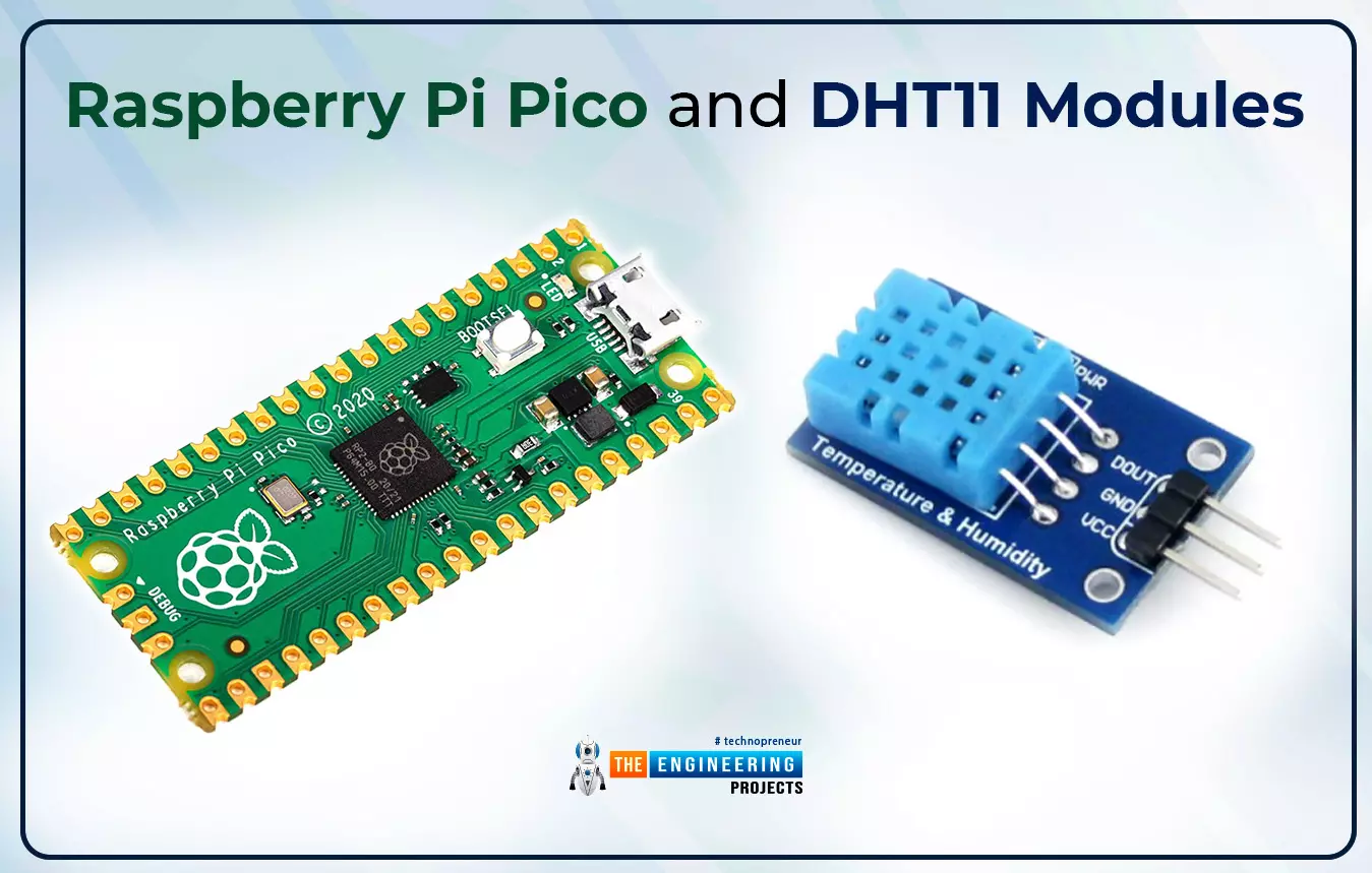
Now let’s learn how to interface sensor modules with the Raspberry Pi Pico module. So, in this tutorial, we will learn how to interface the DHT11 sensor with the Raspberry Pi Pico module and fetch the observed data (from its surrounding) using the MicroPython programming language.

Before writing the code for interfacing and fetching the data from the respective sensor, let’s first have a look at the working operation, features and properties of the DHT sensor.

Fig. 1 Raspberry Pi Pico and DHT11 modules

DHT11 Sensor


The DHT11 sensor (also known as a temperature and humidity sensor) is a sensor module that measures humidity and temperature in its immediate environment. The ambient temperature and humidity of a given area are monitored by this sensor module. The sensor is made up of an NTC (negative temperature co-efficient) temperature sensor and a resistive type humidity sensor. An 8-bit microcontroller is also built into the sensor module. The microcontroller converts analogue to digital and outputs a digital signal through the single wire protocol.

The following are some of the DHT11 sensor's technical specifications:

Table:1 DHT11 technical specifications

DHT11 sensors can also be used to create a wired sensor system with up to 20 meters of cable.

A DHT sensor is mostly used in weather monitoring systems and for research purposes. Although we have satellites to provide the status of weather conditions but, the data provided by satellites represent a larger area. In the case of research applications, the satellite provided data is not sufficient so in such applications, we need to use sensor modules like DHT.

DHT11 Vs DHT22

To measure temperature and humidity, two DHT modules (DHT11 and DHT22) are available in the market. Both of the DHT11 and DHt22 modules, serves the same purpose, but they have different specifications. The DHT22 sensor, for example, has a wider range of humidity and temperature sensitivity. The temperature sensitivity of DHT22 ranges from -40 to 80°C with +-0.5°C tolerance and on the other hand, the temperature sensitivity of the DHT11 sensor ranges from 0 to 50°C with +-2°C tolerance.

Similarly, the humidity sensitivity of the DHT22 sensor ranges from 0 to100% with +-2% tolerance and for DHT11 the humidity sensitivity rages between 20 to 90% with +-5% tolerance. Similarly other properties like resolution, sampling time etc are better in the DHT22 sensor module than in DHT11. But the only disadvantage or drawback of the DHT22 sensor module is its cost. The DHT22 is costlier than DHT11 sensor module. So you can use any of the modules as per your requirements and resources.

Software and Hardware components required

The software and hardware components required to interface the DHT sensor with the Raspberry Pi Pico board are:

  • Raspberry Pi Pico development board
  • DHT11 sensor
  • A resistor (10K)
  • Connecting wires
  • Breadboard
  • Data cable
  • Thonny IDE

Fig. Required Components (hardware)

DHT11 Pin-out

DHT11 is a three pin module and the pins include ‘+Ve’ for 3.3V, ‘-Ve’ for ground and the third one is ‘OUT’ for data output.

Fig. 3 DHT11 Pin-out

Interfacing DHT11 with Raspberry Pi Pico module

The connection for interfacing the DHT11 and Pico modules are shown in table 1. There are basically three pins in DHT11 sensor as discussed earlier. Two pins are to power up the DHT11 module i.e., VCC and ground and these two pins are connected to the 3.3V and GND pins of the Pico board. The third pin i.e., ‘OUT’ is used to provide data input to the Raspberry Pi Pico board. The data (‘OUT’) pin can be connected to any of the GPIO pins of the pico board. So here we are using GPIO_0 pin for data input.

Table 2 Interfacing DHT11 with Raspberry Pi Pico

Fig. 4 Interfacing DHT11 with Pico board circuit

Programming

The development environment we are using is Thonny IDE, to program the Raspberry Pi Pico board for accessing the dual core feature with MicroPython programming language.

So, before writing the MicroPython program user need to install the respective development environment to compile and upload the MicroPython program into the Pico board.

We already published a tutorial on how to install and access Thonny IDE for Raspberry Pi Pico programming using MicroPython programming language. Follow our previous tutorial, to install Thonny IDE for raspberry pi pico programming.

Let’s write the MicroPython program to interface the DHT sensor with the Raspberry Pi Pico module and fetch the temperature and humidity data observed with the DHT11 sensor.

  • The first task while writing the MicroPython code for the DHT11 interfacing is importing the necessary classes and modules. Firstly we are importing the Pin class from the machine The Pin class is used to access the Raspberry Pi Pico’s GPIO pins to interface the data pin of DHT11 sensor module.
  • Next we are importing the utime module to add delay when required.
  • The third module we are importing is the dht module which is responsible for reading the temperature and humidity data from the sensor module.

Fig. 5 importing necessary library files

  • Next we are declaring a ‘pin’ object. This object represents the GPIO pin number to which the data pin of DHT11 is to be connected and also the mode of the GPIO pin. Here we are using GPIO_0 of the Pico board and the pin is configured at imput.

Fig. 6 declaring the ‘pin’ object

  • We are using a while loop to continuously read and print the sensor reading (temperature and humidity).
  • The sampling rate of DHT11 sensor is 1 second. So before reading the data from DHT sensor a minimum delay of 1 second is required. Here we are adding a delay of 2 second.
  • The temperature observed using ‘dht_input.temperaure’ The respective data is store inside ‘temp’ variable and then printed using print() command.
  • Similarly, for humidity the data is observed using ‘dht_input.humidity’ The respective data is stored inside ‘humidity’ variable and printed using the print() command.

Fig. 7 Main loop

Main program (main.py)

# importing necessary library files

from machine import Pin

import utime

from dht import DHT11, InvalidChecksum

while True:

utime.sleep(2) # adding delay of 2 seconds

pin = Pin(0, Pin.OUT, Pin.PULL_DOWN) # declaring pin object

dht_input = DHT11(pin) # defing the sensor pin

temp = (dht_input.temperature) # reading temperature

humidity = (dht_input.humidity) # reading humidity

print("temp(°C): {}".format(dht_input.temperature))

print("humidity(%): {}".format(dht_input.humidity))

You can use the above code as it is. But before compiling the code make sure you have uploaded the dht.py library file to your system/Raspberry pi pico module.

To upload the dht.py file into your system/pico board, go to File >> New, as shown below:

Fig. 8 create a new program

  • Paste the below attached code into the new program and save the program to similar location where the main program is saved.

DHT library (dht.py)

import array

import micropython

import utime

from machine import Pin

from micropython import const

class InvalidChecksum(Exception):

pass

class InvalidPulseCount(Exception):

pass

MAX_UNCHANGED = const(100)

MIN_INTERVAL_US = const(200000)

HIGH_LEVEL = const(50)

EXPECTED_PULSES = const(84)

class DHT11:

_temperature: float

_humidity: float

def __init__(self, pin):

self._pin = pin

self._last_measure = utime.ticks_us()

self._temperature = -1

self._humidity = -1

def measure(self):

current_ticks = utime.ticks_us()

if utime.ticks_diff(current_ticks, self._last_measure) < MIN_INTERVAL_US and (

self._temperature > -1 or self._humidity > -1

):

# Less than a second since last read, which is too soon according

# to the datasheet

return

self._send_init_signal()

pulses = self._capture_pulses()

buffer = self._convert_pulses_to_buffer(pulses)

self._verify_checksum(buffer)

self._humidity = buffer[0] + buffer[1] / 10

self._temperature = buffer[2] + buffer[3] / 10

self._last_measure = utime.ticks_us()

@property

def humidity(self):

self.measure()

return self._humidity

@property

def temperature(self):

self.measure()

return self._temperature

def _send_init_signal(self):

self._pin.init(Pin.OUT, Pin.PULL_DOWN)

self._pin.value(1)

utime.sleep_ms(50)

self._pin.value(0)

utime.sleep_ms(18)

@micropython.native

def _capture_pulses(self):

pin = self._pin

pin.init(Pin.IN, Pin.PULL_UP)

val = 1

idx = 0

transitions = bytearray(EXPECTED_PULSES)

unchanged = 0

timestamp = utime.ticks_us()

while unchanged < MAX_UNCHANGED:

if val != pin.value():

if idx >= EXPECTED_PULSES:

raise InvalidPulseCount(

"Got more than {} pulses".format(EXPECTED_PULSES)

)

now = utime.ticks_us()

transitions[idx] = now - timestamp

timestamp = now

idx += 1

val = 1 - val

unchanged = 0

else:

unchanged += 1

pin.init(Pin.OUT, Pin.PULL_DOWN)

if idx != EXPECTED_PULSES:

raise InvalidPulseCount(

"Expected {} but got {} pulses".format(EXPECTED_PULSES, idx)

)

return transitions[4:]

def _convert_pulses_to_buffer(self, pulses):

"""Convert a list of 80 pulses into a 5 byte buffer

The resulting 5 bytes in the buffer will be:

0: Integral relative humidity data

1: Decimal relative humidity data

2: Integral temperature data

3: Decimal temperature data

4: Checksum

"""

# Convert the pulses to 40 bits

binary = 0

for idx in range(0, len(pulses), 2):

binary = binary << 1 | int(pulses[idx] > HIGH_LEVEL)

# Split into 5 bytes

buffer = array.array("B")

for shift in range(4, -1, -1):

buffer.append(binary >> shift * 8 & 0xFF)

return buffer

def _verify_checksum(self, buffer):

# Calculate checksum

checksum = 0

for buf in buffer[0:4]:

checksum += buf

if checksum & 0xFF != buffer[4]:

raise InvalidChecksum()

Once both the main.py and dht.py are saved successfully we are ready to run the program. Click on the Run icon to test the interfacing setup and check the respective results.

Results

To see the sensor reading (temperature and humidity) observed with DHT11 sensor and Pico module we can either interface some peripheral device like LCD display or OLEDs. But for now we are just printing the sensor reading on Shell. We will create another tutorial for interfacing a peripheral display device with Raspberry Pi Pico module.

The sensor readings observed with DHT11 sensor are printed on the Shell. Image of the observed temperature and humidity values is attached below:

Fig. 9 DHT11 output

Conclusion

In this tutorial, we learned how to interface a peripheral sensor with the Raspberry Pi Pico module to observe temperature and humidity and display the data on Shell. This concludes the tutorial. I hope you found this of some help and also hope to see you soon with a new tutorial on the Raspberry Pi Pico programming series.

Introduction to Ions

Hello, students here in our previous tutorial we study molecules and now I am with a new topic “Ion” which might be possible for some of my readers this article seems to be new, and some of my readers may be familiar with this term. But no matter whether we know or not, in my article I try to cover all aspects of this term. Many questions arise in your mind such as you may think;

What is an ion?

How ions are formed?

What are the different types of an ion?

What methodology is utilized for assigning charge to an ion?

What are examples of an ion?

Which methods are used for the creation of an ion?

If my readers want to know the answers to these questions, hold copies and pencils in your hand and stick to my article till the end.

Brief description of an Ion

What is an ion?

Definition

An atom or group of atoms that brings a positive or negative electric charge as a conclusion of including lost or achieved one or more electrons

Or

A charged subatomic particle (such as a free electron)

By the word an Ion, it's not wrong to say that it is the type of chemical species which may hold two types of charges with some magnitude. These charges may be positive or negative with some magnitude. Those atoms or molecules that have unequal net charges associated with them simply say that charges on them are not involved in a factor of zeros, we use the term an ion for such types of atoms.

A short view over term atom.

Atom

As this term is the basis of chemistry everyone is familiar with this term. For understanding the article in a better way I explain it. Atom is the smallest component that constitutes the property of an element. An atom has a heavy central Part which is known as the nucleus. In the nucleus, two types of charges are present one is a proton carrying a positive charge and the other is a neutron neutral particle. Overall there is a positive charge in the nucleus. Around the nucleus, there are several circular orbits in which electrons keep moving the nucleus. In each orbit, electrons feel a nuclear pull that restricts their motion in a circular orbit.

Back to our statement that ions have a non-zero net charge. By non-zero net charges, it concluded that may an atom have more protons ( sub particle of an atom that consists of a positive charge. These charges are present inside a nucleus) than several electrons ( sub particle of an atom constituting a negative charge and present outside the nucleus, keep in motion in orbits around the nucleus) or secondly, maybe there are a greater number of electrons than the number of protons in their atomic or molecular structure. Thus we can say that a charged atom or molecule is named an ion. It is charged because we see that the number of protons and electrons is unequal.

Different types of an ion

Two conditions of inequality of charges between sub-particles of an atom are mentioned. Depending upon these two conditions we can categorize an ion into two different types either positive ion (cation) or negative ion(Anion).

What is a cation?

According to the first condition, when the number of protons is greater than the number of the electron in an atom, then the atomic structure is knowns to be positively charged. Such positively charged atoms are known as cations or positively charged ions. The charge on a cation depends upon the tendency of an atom to lose electrons from the shell. If one electron is removed then the charge is +1, if two electrons are removed from the shell then the cationic charge is +2 as illustrated in the given below example.

  • It has been seen that the formation of cation is an endothermic reaction.

What does mean by term Endothermic?

The word endothermic means heat absorbing. Endothermic reactions or processes are those in which there is a need for absorption of heat to carry out the reaction.

Why it is an endothermic reaction let’s allow me to explain:

  • Cation is formed when an isolated atom loses one or more electrons from its valance shell. As we know that there is the existence of a strong force of attraction in an atom. Due to this force of attraction nucleus strongly attract the valance electron, to remove an electron from a strong grip of the nucleus a sufficient amount of energy is required. This sufficient amount of energy is given to the electron which energies it and helps it to kick off from the strong field of the nucleus. As soon as the electron removes from the nucleus field it left behind a positive charge. Which is named cation. That’s why the formation of cations is an endothermic process.

Ionization energy:

The amount of energy that is required to pull out an electron from the valance shell of an atom is named ionization energy. An example is given below to illustrate the above statement:

Here 496 KJ/mole energy is required to form positive cation sodium from an isolated sodium atom.

  • If we compare a cation with a parent atom by their size we concluded that A Cation is smaller than the parent atom. Why does this so happen?

When a positive cation is formed then the number of protons increases as compared to the number of electrons. As one or more electron are removed from the valance shell, there is the removal of the shell from an atom result in an increase in the nuclear pull on the remaining valance electron. That’s why the cation is less than the parent atom by its size.

How does a cation Represent symbolically and what charge does it constitute?

  • It possesses a positive charge and suffix (ium) is used for cation. Such as Hydronium (H+)

What is Anion?

  • Secondly when an atom has more electrons than the number of protons then the charged atom is referred to as an Anion or negatively charged ion. In other words, we can also say that an anion is formed when an isolated atom gains an electron.
  • It has been seen that the formation of anion is an exothermic process.

What is meant by the word Exothermic?

An exothermic process is a process that occurs with the liberation of heat or energy. An anion or negatively charged ion is formed when an extra electron is gained by an isolated atom, this addition of extra electrons increases the energy of the atom resulting in instability of an atom. To attain stability, as the atom earlier it loses energy in form of heat. Thus the formation of uni-negatively ion is an exothermic process. Given below there is an example mentioned to explain the above statement:

Here when an electron is added to an isolated atom of chlorine, an amount of energy 349 KJ/mole is liberated. Which makes the reaction exothermic reaction.

  • Size of an anion is always greater than the parent atom. As we see that during the formation of an anion one or more electrons are added to the atom. This extra addition of electrons increases the electron-electron repulsion in the valance shell of an atom which results in an extension of the electronic cloud. Due to an increase in some electrons in the outermost shell, the pull of nuclear on valance electron also Decreases. That’s why the size of an anion is always greater than the parent atom.

How does a cation Represent symbolically and what charge does it constitute?

It possesses a negative charge and the suffix (ide) is used for monoatomic anion and (ate) for the polyatomic anion. Such as hydride and hydrate.

Ionic bond and ionic compound:

As there is two type of charged ions one is a positively charged cation and the other is a negatively charged anion, due to their opposite polarity an electrostatic force of attraction arises between them. This electrostatic force worked as a driving force in the formation of an ionic bond. When two charges formed an ionic bond then a compound is formed which is named an ionic compound.

Classification of Ions:

Depending upon the type of atom from which an ion is formed we can classify it as a monoatomic, diatomic, or polyatomic ion.

Mono-atomic ion:

If an ion is formed from one type of atom it is referred to as a monoatomic ion. Examples of monoatomic cation and anion are;

  • Aluminum cation is represented by the empirical formula Al?³.
  • Proton is a commonly known caption of the hydrogen atom. This hydrogen caption is denoted by H ?¹
  • Another example of a mono-atomic ion is manganese cation which is represented by the formula Mn ?². It also can form Mn ?³ and Mn ?4.

Illustration of monoatomic anion:

  • Common example of a uni-negative ion is the fluoride ion which is represented by Fl ?¹.
  • Along with this other examples are chloride ion, bromide ion, iodide ion, sulfide ion represented by chemical formula Cl?¹,

Br? ¹, I ?¹, S ?². As these belong to the 7th group, to complete their outermost shell they always prefer to gain an electron to form an anion.

Di-atomic ion:

If from two types of atoms an ion is made then it is referred to as a diatomic ion. An example of a diatomic ion is an Oxide ion denoted by the chemical formula O? ².

Polyatomic ion:

When an ion is made from more than one type of atom then it is referred to as a polyatomic or molecular ion.

Illustration of polyatomic cation:

Here below there are some common examples are provided;

  • H3O? is the chemical formula of hydronium cation.
  • Hg2?² is a mercurous cation.
  • NH?4 is the chemical formula of ammonium cation.

Illustration of polyatomic anion

  • A nitrate ion is a common example of a polyatomic anion. It is represented by the chemical formula NO3?.
  • Cr2O3? is the chemical formula of chromium oxide anion.
  • Another example of a polyatomic anion is the Sulfate ion which is represented by the chemical formula SO4?².

Ways one can create an ion;

There are several techniques one can use to create an ion. Here I explain two methods;

  • Spontaneous collision
  • Chemical interaction

Spontaneous collision:

  • We can create an ion from a spontaneous collision. Byword spontaneous means an event occurs without any apparent external cause. Collision is a process in which two bodies violently interact with each other. Through spontaneous collision among molecules of the liquid, an electron or group of electrons may be knocked off from an atom resulting in the formation of an ion. This ion is positively charged. Along with a positively charged ion, a free electron is also formed. This type of ionization is commonly named physical ionization. The free-electron that comes into the process during the collision may stick to itself or another atom resulting in the formation of a negatively charged ion.

Chemical interaction

  • One can create an electron through another process which is commonly known as “ chemical interaction”. For example when we dissolve an ionic compound in any form of a solvent such as water. The atom that comprises salt undergoes the process of separation to form a negatively charged anion & positively charged cation. A common example one can see to understand this process is the dissolving of common salt (sodium chloride) in water. When sodium chloride is dissolved in water then NaCl disassociates into positive sodium cation and negative chlorine anion.

Here Na+ represent positive cation ionic specie. And Cl- represent anionic specie.

  • Another process that can be carried out for the formation of ions is the passage of direct current from a dissolved solution which can conduct. As the current is passed through the solution the liquid molecules break and positive and negative ions are formed.

That’s All today. In this article, we learn about ion, its type, and the representation of charges on the ion. I try to explain aspects that make cation and anion quite different from each other. And in last we studied techniques which normally used to create an ion. I hope the given material for the term “Ion” is helpful for your academic requirement. If you have any queries regarding this article. Mention your question in the comment session. In the next tutorial, we will learn about molecular ions. Our platform tries its best to satisfy you. Keep tuned.

Introduction to Atoms

Hello, friends today we will discuss the basic concept of chemistry it is our first tutorial series in which we will discuss:

  1. Atom
  2. Molecule
  3. Ion
  4. Molecular ion

Now in this article, we will discuss atoms. Its definitions, examples, properties, its evolutionary history, and also some important facts in the form of questions.

Atom

Definitions

A tiny particle that cannot be seen with a naked eye so-called atom.

Or

Atom is the lowest unit of matter and is often divided without the discharge of electrically charged particles.

Or

Atom is the introductory structure block of chemistry.

Examples

From molecule;

Hydrogen (H2)

  • It has two atoms.

Nitrogen (N3)

  • It has three atoms

From elements;

Helium(He)

  • It has two electron

Properties

We discuss different properties of atoms like:

Atomic no:

The no of protons present in the nucleus of an element is called atomic number Or nuclear charge no.

. Its symbol is Z.

  • Always a whole no
  • No effect of neurons on atomic no.
  • Always give a smaller value than atomic mass.

Examples

  1. Carbon has 6 protons in its nucleus so its atomic no is Z=6
  2. Sodium has 11 protons .so Z= 11

Atomic mass

The sum of the numbers of neutrons and protons in the nucleus of an atom is called atomic mass or mass no.

  • It is represented by A and calculated as A=Z+n
  • Where n is no of neutrons and Z is no of protons
  • It always is greater than atomic no.
  • It is affected by the addition of neutrons.

Example

Sodium has 11 electrons = 11 protons and 12 neutrons in an atom. So its mass no is

A= 11+12= 23

Periodic table

In this table, we can see atomic numbers, atomic mass, and symbols of atoms. Above the symbol is atomic no and below is the atomic mass.

Atomic size.

  • We can not measure the size of an atom because atoms have no boundaries and they are very tiny, so can assume spherically
  • It decreases if the atomic no is decreased from left to right in a period.
  • In groups, atomic size gradually increases from top to bottom.

Atomic radius

The distance between the nucleus and the outermost orbit of the electrons of an atom is called atomic radius or atomic radii.

Relative atomic mass

The relative mass unit or atomic weight open element is defined as the number of atoms of an element in grams contained in 12 grams of carbon _12(isotope)

Atomic mass unit

The atomic mass unit or Dalton is defined as the one-twelfth of the mass of a carbon atom.

  • It is also called Dalton.
  • Its symbol is amu.

Interactions between atoms ( bonds)

Types of bonds

  • Ionic bond
  • Covalent bond
  • Dative covalent bond
  • Metallic bond

Ionic bond:

This type of bond is formed by the complete transfer of an electron from one atom to another.

Example

  • Only valence electrons( electrons in the last shell) can take part in ionic bonding while others are not.
  • In ionic bond formation, heat is released.

Covalent bond:

In this type of bond, electrons are mutually shared between two atoms.

Types

  1. Single covalent bond
  2. Double covalent bond
  3. Triple covalent bond
  4. Metallic bond

Single e covalent bond:

In which one bond pair of electrons is formed by the contribution of an electron by each bonded atom.

  • Indicated by a single line

Double covalent bond:

In which two bond pair is formed by the contribution of electron pair from each atom.

  • Indicated by double lines

Triple covalent bond:

In which three bond pairs are formed by the contributions of three electrons from each bonded atom.

  • It is indicated by three lines.
  • Each bonded atom attains octet by sharing of bond pair of electrons and attaining the nearest noble gas configuration.

Dative covalent or coordinate covalent bond:

A bond is formed between the electron pair donor and the electron pair acceptor.

  • The atom which invests a pair of electrons is called a donator.
  • The atom that receives that electron pair is called the acceptor.
  • Those valence electrons that are not taking part in bonding and available on an atom like the one available on nitrogen in ammonia.

Example:

Polar covalent bond:

Those covalent bonds in which hetero atom takes part and one attracts the bond pair of an electron more strongly than the other.

None polar covalent bond:

If a covalent bond is constituted in which two similar atoms shared pair of the electron is excited by the both equally. such a type of bond is called a nonpolar covalent bond.

Predominantly covalent:

If the electronegativity between two elements is more than 1.7 the bond between them will be predominantly ionic and if it is less than 1.7 the bond between two atoms will be predominantly covalent.

Metallic bond:

A metallic bond is formed due to free electrons.

Evolutionary history of the atom

Timeline: 400 BC.

Scientist: Democritus

Theory of universe:

A first-person who uses the term atom(mean individual derived from atoms) was a Greek philosopher. He says that if you divided a piece of matter and divide and continue dividing, at any moment reach when you can’t divide it more, that fundamental unit was Democritus called an atom.

  • Atom is made from matter and can not be seen by the necked eye.
  • Between atoms, there is a space.
  • Atoms are in the form of a solid-state.
  • There is no internal structure in an atom.
  • Every atom has a different shape, size, and weight.

Timeline:1800s

Scientist: Jhon Dalton

  • The first person presents an atomic model of the behavior of the theory of the behavior of atoms consisting of small particles.
  • Atoms cannot change their shape and are indestructible.
  • By the weight of atoms, their elements can be characterized.
  • Atoms combined to firm a compound.

Timeline: 1890s.

Scientist: Thomson

J.JThomson was a physicist who use cathode ray tube technology to discover electrons.

  • In this tube, the air has been sucked out.
  • An electric charge travels from cathode to anode
  • Florescent gas light up the whole tube and the charge in it is invisible. When a charge hits the beam, a dot will appear on the screen.
  • A beam of light travel in a straight line in a fluorescent tube.
  • Each coil has a specific charge on a deflection.
  • From a negative coil, the charge would defect away as Thomson shows.
  • So he formed that charge this a negative charge.

When he found that negative charge, he did not stop and did a series of experiments, he discover the mass of the electron. He found that the mass of an electron is 1000 times lighter than a hydrogen atom. He made a statement saying that an electron must be inside an atom. Before it, he says the negative charge corpuscles later his name was changed and named as an electron.

Thomson’s atomic model

Using her prediction, he discovered what an atom looks like?

  • His model was named plum pudding model his name.
  • Each atom has a spherical shape and is inserted with positively charged fluid. He says it sticky jam part of a pudding.
  • In this fluid, corpuscles (electrons) are the negatively charged particles suspended. He compared it to plum in the pudding.
  • The movement of these electrons is not discovered by Thomson.

Timeline: 1910’s.

Scientist: Ernest Rutherford

Sir Rutherford made a famous gold foil experiment and proved the Thomson atomic model.

  • He fired positively charged alpha particles at a gold foil.
  • He estimated the deflection came out the other side.
  • Every particle has not been deflected. Every particle would deflect back in all the ways.
  • He assumed that the center of the foil must be positive. He called his nucleus.

Rutherford's Atomic model

  • The nucleus consists of positively charged particles.
  • The electrons revolve around the nucleus.
  • He faces one problem: Why nucleus can’t attract the electrons?
  • He compared the atom with a mini solar system in which electrons revolve around the nucleus in a fixed orbit due to this he called his planetary model

Timeline:1910’s

Scientist: Neils Bohr

Niels obeys the planetary model but he found some disadvantages. He could answer the Rutherford question

Why electrons do not fall into the nucleus?

He replies with a perfect answer to the question because of his knowledge of quantum physics and energy.

Bohr's atomic model:

  • Electrons have fixed energy and size in orbits of the nucleus.
  • The energy of an electron depends on the orbit in which the electron revolves.
  • Electrons fill the lower orbit first.
  • If the first energy level(orbit) is filled then the next will began to fill.
  • When an electron moves from one orbit to another, the radiation process occurs.

There is a problem with this theory: Electrons could not move in a specific path or orbit.

Timeline:1920’s

Scientist: Erwin Schrodinger

He was a revolutionary physicist and he presented the atomic model by using Heisenberg’s uncertainty principle.

Schrodinger’s atomic model(Aka the cloud model)

  • An electron would not revolve in a fixed orbit.
  • We can find out where it likely is.
  • Energy level depends upon the type of probability of orbit described by Bohr.

Facts

What is not an atom?

By the definition, atoms are the units of matter, so those are not atoms that do not consist of matter.

Parts of atoms that are not associated with a proton are not atoms.

An electron is not an atom, also neutrons bonded to other neutron is not an atom.

Why does an atom react?

Atoms react for attaining the nearest noble gas configuration and become more stable by following the duplet or octet rule.

Why the shape of the atom is spherical?

We can say that an atom “has the shape of the sphere” because a positively charged nucleus is at the very center, and the negatively charged electrons are distributed around it. The electrons are attracted to the nucleus and repel each other. A nucleus, the mass of neutrons and protons within an atom, arranged itself in a roughly spherical shape.

Why the revolving electron does not fall into the nucleus?

Electrons revolve in fixed energy levels around the nucleus. It can not befall into the nucleus because electrons do not radiate energy and move in a circular orbit due to necessary centripetal force.

Why neutrons are neutral and do they exist in the nucleus?

We have an idea from its name, the neutron is the neutron. In other words, the interaction between protons and electrons can cause the formation and destorarion of neutrons. As electrons are negatively charged and protons are positively charged particles. So they cancel each other charge and that’s why neutrons carry no charge and they are neutral. They exist in the nucleus for the stability of nuclei.

Why carbon 12 is used in the references of all atomic mass units?

At the start, hydrogen is used to measure but it gives a fraction. so it would be changed into oxygen, Scientists used a mixture of natural oxygen but it led to confusion. So again changed the reference and turned it into carbon – 12. We use this because it gives all the atomic mass units in exact no. The reason is the different ratio of the mass of proton and neutron performing the change of nuclei.

I Hope, I cover all aspects of the atom, in the next tutorial we will learn about the molecules. If someone has any questions about the atom I will try to answer them. write it in the comment box. Thanks

Raspberry Pi Pico Dual Core Programming with MicroPython

Hello readers, I hope your all are doing great. We know that a Raspberry Pi Pico module comes with multiple inbuilt features for example onboard memory, processing units, GPIOs or General Purpose Input Outputs (used to control and receive inputs from various electronic peripherals) etc.

In our previous tutorials, we discussed how to access GPIO pins of the Raspberry Pi Pico module for both input as well as output operations.

In this tutorial, we are going to discuss another important feature of the Raspberry Pi Pico module (RP2040) which is Dual Core Processor. The Pico board features with 133MHz ARM Cortex-M0+, Dual Core Processor. This dual-core feature makes the Pico module capable of multiple thread execution or multithreading.

Now before writing the MicroPython program let’s first understand the concept of the dual-core processor in the Raspberry Pi Pico module.

Fig. 1 raspberry Pi Pico dual-core programming

Raspberry Pi Pico Dual Core

A core is the basic unit of any processor which is responsible for executing program instructions. A multi core processor comes with the features of executing multiple tasks at a time. Multithreading is the ability of a processing unit to provide multiple threads of execution simultaneously (operating system supported). In multithreading, threads share their resources with each other. So this dual-core processor feature results in increased processing speed.

Raspberry Pi Pico (RP2040) module is having two processing cores, Core0 and Core1. In the default mode of Raspberry Pi Pico program execution, Core_0 executes all the tasks and Core1 remains idle or on standby mode. Using both the cores of RP2040 provides us with two threads of execution and hence a more powerful project with better processing speed.

Both core0 and core1 execute their assigned tasks independent of each other while sharing all the resources like memory space and program code with each other. Sharing the memory location between two cores can create race conditions and hence can cause trouble when mutual memory accessing is not assured. On the other hand, sharing program code with each other (core0 and core1) may sound troublesome but practically it is not. The reason is fetching code is a read instruction that does not create a race condition.

Core0 and Core1 communication

Fig. 2 Core_0 and Core_1 communication

As we mentioned above, sharing memory space with two cores simultaneously can cause race conditions. So, to make the cores to communicate with each other the Raspberry Pi Pico module is featured with two individual ‘First In First Out’ (FIFO) structures. Each core can access only one FIFO structure so both core have their own FIFO structure to write codes which helps in avoiding race condition or writing to the same memory location simultaneously.

You can follow the given link for detailed study on Raspberry Pi Pico: https://www.theengineeringprojects.com/2022/04/getting-started-with-raspberry-pi-pico.html

Software and Hardware components required

  • Raspberry Pi Pico development board
  • Thonny IDE
  • Data cable
  • Connecting wires
  • Breadboard
  • LEDs

Programming

The development environment we are using is Thonny IDE, to program the Raspberry Pi Pico board for accessing the dual core feature with MicroPython programming language.

So, before writing the MicroPython program user need to install the respective development environment.

We already published a tutorial on how to install and access Thonny IDE for Raspberry Pi Pico programming using MicroPython programming language. You can find the details at the given link address: https://www.theengineeringprojects.com/2022/04/installing-thonny-ide-for-raspberry-pi-pico-programming.html

Now let’ write a MicroPython program with Thonny IDE to access raspberry Pi Pico’s both cores:

In this example code we using just a simple “print()” commands to print the messages from each core for testing purpose.

  • The first task while writing a code is importing necessary libraries. Here we are importing three libraries, “machine”, “utime” and “_thread”.
  • utime library provides the access to internal clock of raspberry Pi Pico module which is further used to add delay when required.
  • _thread library is responsible for implementing the threading function provided by “Raspberry Pi Pico” community.
  • As we are using a dual core processor and accessing both the cores simultaneously means we are using two threads (one thread from each core). This _thread module allows a user to work with multiple threads and also allow them to share global data space.
  • For more details on _thread module follow the given link: https://docs.python.org/3.5/library/_thread.html#module-_thread

Fig. 3 Importing necessary libraries

  • Semaphores or Simple locks are provided with “_thread” module which is responsible for synchronization between multiple threads. The allocate_lock() function provided with _thread module is responsible for returning a new lock object.
  • Here we are declaring a “spLock”

Fig. 4 declaring thread lock object

  • Next, we are creating a function where we are assigning the task to core_1.
  • The “spLock.acquire()” function “acquires the thread lock without any optional argument”. The reason for using the this “acquire()” function is to make sure that only one thread of execution is acquiring the lock at a time until the lock is released for other thread. Here we using the “print()” command as a task assigned or to be executed by core_1 along with a delay of 0.5sec or 500us.
  • Next, is the release() command, which is used to release the lock acquired earlier. So that other threads can execute their respective tasks.
  • The task assigned to core_1 will be executed continuously because it is written in “while loop”.

Fig. 5 Task for Core_1

  • The function core1_task() defined earlier which is containing the task assigned to core_1 will be passed as an argument inside start_new_thread() function. As per the official documentation from python.org, this function is responsible for “starting a new thread and returning its identifier”. The thread will execute the assigned function (as an argument). The tread will automatically exit when the function returns. We can even assign more than one argument in this “-thread.start_new_thread()” function.

Fig. 6 Core_1 thread

  • As we mentioned earlier, Raspberry Pi Pico uses core_0 as default a core for processing purpose. So here we do no need to use the _thread.start_new_thread() function to start a new thread for Core_0. Core_0 will automatically start a thread for code execution. But we still need to call the acquire(a lock) and then release functions, just to ensure only thread is acquiring the lock at a time. Here again we are using the print() command to print a message from core_0 like we did in case of Core_1.

Fig. 7 Task for default core (core_0)

Code

The MicroPython code with thonny IDE for Raspberry Pi Pico is written below:

import machine

import utime # access internal clock of raspberry Pi Pico

import _thread # to access threading function

spLock = _thread.allocate_lock() # creating semaphore

def core1_task():

while True:

spLock.acquire() # acquiring semaphore lock

print( "message from core_1")

utime.sleep(0.5) # 0.5 sec or 500us delay

spLock.release()

_thread.start_new_thread(core1_task, ())

while True:

spLock.acquire()

print( "message from Core_0 ")

utime.sleep( 0.5)

spLock.release()

  • Copy the above code and paste in your Thonny IDE window.
  • Save the code either on Raspberry Pi Pico or your computer and once it is successfully saved click on the ‘Run’ icon to run the code.
  • Now go to Shell section to check the result. If the Shell is not enabled then go to View >> Shell and check ‘Shell’.
  • Now in the shell section you should see the message printed from both the cores.

Fig. 8 Enabling Shell

Result

The result obtained from the above code is attached below. Where we can see the messages received or executed by both the cores as per the instructions provided in the micropython code.

Fig. 9 output printed on shell

Let’s take another example where we will interface some peripheral LEDs and will toggle those LEDs using different threads of execution or cores.

  • Most of the instructions are similar to the previous example with some additional ones. Here we are importing one more library ‘Pin’ (along with the previous ones) to access the GPIO pins of raspberry Pi Pico module.

Fig.10 importing necessary libraries

Fig. 11 declaring led objects

  • Next task is assigning the task for each core. Core_1 is assigned to make the led_1 (GPIO_14) to toggle along with printing the given message.

Fig. 12 Toggling LED with core_1

  • Core_0, which is the default one is assigned to make the led_0 (i.e., GPIO_15) toggle with a delay of 0.5sec. Rest of the programming instructions are similar to the previous example code so we are not explaining them again.

Fig. 13 toggling LED with core_0

Code

from machine import Pin

import utime # access internal clock of raspberry Pi Pico

import _thread # to access threading function

# declaring led object

led_0 = Pin( 14, Pin.OUT ) # led object for core_0

led_1 = Pin( 15, Pin.OUT ) # led object for core_1

spLock = _thread.allocate_lock() # creating semaphore lock

def core1_task():

while True:

spLock.acquire() # acquiring semaphore lock

print( " message from core_1" )

led_1.value( 1)

utime.sleep( 0.5) # 0.5 sec or 500us delay

led_1.value(0)

spLock.release()

_thread.start_new_thread( core1_task, () )

while True:

spLock.acquire()

print( "message from Core_0" )

led_0.value(1)

utime.sleep( 0.5)

led_0.value(0)

spLock.release()

Result

In the results attached below we can that two LEDs are attached with raspberry Pi Pico boar. Green (GPIO14) and Red (GPIO15) LEDs represent the output of Core_1 and Core_0 respectively.

Fig. 14 Core_1 output (GPIO 14)

Fig. 15 Core_0 Output (GPIO15)

Conclusion

In this tutorial, we learned how to access both the cores of the raspberry pi Pico module and to execute task or control peripherals with individual cores. We also learned the concept of threading and multithreading.

This concludes the tutorial. I hope you found this of some help and also hope to see you soon with a new tutorial on raspberry Pi Pico programming.

Role of IoTA in Industrial IoT- Industry 4

The Industry 4.0 market size will reach $267.01 billion by 2026. Industry 4.0 depends on the secure, fast, and cost-effective data transfer between IoT devices. IoTA is designed to ensure secure communication between two devices within the IoT(internet of things) framework. Let's have a detailed look at the role of IoTA in industrial IoT.

Understanding IoTA- how it's different from blockchain

The terms MIOTA and IoTA together make up the term IoTA. While MIOTA is a cryptocurrency, IoTA is a non-profit foundation. Since its inception in 2015, IoTA has formed joint ventures with firms like

  • Fujitsu
  • Samsung
  • Telekom
  • Volkswagen

IoTA is technically different from blockchain in terms of the underlying technology. IoTA works on a technology called DAG (directed acyclic graph). Under the DAG technology, two transactions need to be validated to send one transaction. Apart from this, a proof of work needs to be submitted to validate the transaction. You will find a lot of boxes in the figure given below. Each box represents a transaction. This system of boxes is known as an IoTA tangle.

One of the most distinguishing features of the IoTA tangle is that, unlike blockchain, it can work offline. The data can be synchronized later. The ability to work offline happens to be an essential feature to consaider while developing IoT applications. This is because IoT devices often work in scenarios wherein there is no guarantee of a strong internet network.

Now that we have had a look at the basics of IoTA, let's now see why IoTA is important for industry 4.0.

Why is IoTA important for industry 4.0?

The first industrial revolution was industrialization through water and steam power. The second industrial revolution consisted of mechanization through electricity. The third industrial revolution started with the wide-scale adoption of computers in manufacturing. The fourth industrial revolution will be built on what started in the third industrial revolution.

Products will be produced automatically by machines that will talk with each other. All this will be fuelled by machine learning and data science.

The success of Industry 4.0 relies a lot on IoT devices. The IoT devices need a base layer to connect the different industries.

The base layer should have the following characteristics.

  • Able to cater to the entire IoT market
  • Already has successful partnerships
  • Battle-tested products

If there is one technology with all these characteristics, it's IoTA. IoTA is a highly scalable technology that enables fast transactions. Unlike blockchain, there are no fees or mining costs with IoTA.

Key Benefits of IoTA

The following are the significant benefits that IoTA provides.

Tangle properties

IoTA allows for the secure transmission of data. Data sent through other communication channels only proves that someone sends data. With IoTA, it is possible to ascertain whether the same data was sent to everyone else or not and when the data was sent. This feature of IoTA is important because fraudsters can send one set of data to one person and another set of data to another person. The “Notarization" feature of IoTA can be used to prove that an electronic document existed in a physical form earlier and the document has not been changed since its creation.

Lean system

IoTA is a system that is designed specifically for IoT devices like sensors. IoTA is an energy-efficient system that can easily participate in a low-energy network. An IoTA system allows nodes with low hardware resources to participate in the IoTA network.

Fairness

An IoTA system is a fair system as nobody can gain a higher priority in processing by paying more money. Unless the system is congested, all the transactions in an IoTA system are treated equally.

Cost-effective

Unlike blockchain, no mining is required in an IoTA system. This makes IoTA transactions feeless. The ability to conduct feeless transactions is an essential feature of the IoTA system as it enables micropayments to be done easily. Using an IoTA system, you can build a machine-to-machine economy and implement consumption-based payments.

Open-source

The IoTA is an open-source communication protocol. As it is an open-source protocol, everyone can collaborate on the code. Being open-source, the growth of IoTA is exponential as many companies come together in the Tangel EE Working Group and work on solutions for commercial uses.

Industrial use cases of IoTA

There is a wide range of Industrial use cases of IoTA. We have discussed the most popular ones below.

Mobility

Mobility is one area where IoTA can prove helpful. According to research, by 2025, there will be 8 million consumer vehicles that will have self-driving capability.

IoTA tangle allows for secure data transmission between cars and other machines. The vehicles can transact data about weather conditions, traffic congestion and road conditions using IoTA.

IoTA can also enable cars to automatically pay for tolls, parking, battery charging and other services. IoTA makes cars safer and reliable through real-time software updates.

Using IoTA, trucks can do platooning. In platooning, the trucks drive semi-autonomously, with minimum distance between them. Consistent speed creates fuel efficiency and safety, improving the profitability of truck owners.

Supply chain

Around 10% of goods transferred in the global supply chain are fraudulent. The supply chain industry faces trackability, and transparency of goods being transferred is the most prominent issue. IoTA can help resolve these issues.

The logistics companies can keep an immutable and encrypted audit trail of logistical updates with IoTA.

An IoTA-enabled tracking system includes real-time data about weather conditions and geo-location. It also verifies transfer of ownership/custody of goods. Thus, an IoTA-enabled system helps logistics companies improve their trackability and traceability.

Healthcare

IoTA helps healthcare service providers secure patient data. IoTA also helps in democratizing access to healthcare data.

Healthcare researchers can verify the integrity of research data through an IoTA ledger. IoTA can also help companies conduct better pharmaceutical trials. IoTA does this by logging every step and test result of the trial process into the IoTA tangle.

The MAM protocol helps healthcare providers and patients securely exchange patient data.

Smart energy

IoTA can open up doors toward a decentralized peer-to-peer energy trading system.

An IoTA-enabled system can help users to control energy assets remotely. The energy companies can achieve better grid stability and peak shaving through an IoTA-enabled system.

An IoTA-enabled system can provide seamless EV smart charging based on M2M micro-payments.

Industrial IoT

An IoTA enabled smart factory system securely stores the factory data in an IoTA tangle. The IoTA-enabled factory system stores only the encrypted hash in the tangle, thus creating a tamper-proof audit trail.

Through an IoTA-enabled system, the machine owners can lease out entire production lines to people who want to produce products.

Once the products leave the factory, they automatically become part of the smart supply chain. This way, an IoTA-enabled system brings a significantly higher efficiency into the industry.

Closing thoughts

Industry 4.0 is the next leap forward in the growth of mankind, and IoTA will play an important role in deciding the future of industry 4.0. Businesses that want to be a part of the industry 4.0 growth story need to leverage the power of IoTA to achieve exponential business growth.

Syed Zain Nasir

I am Syed Zain Nasir, the founder of <a href=https://www.TheEngineeringProjects.com/>The Engineering Projects</a> (TEP). I am a programmer since 2009 before that I just search things, make small projects and now I am sharing my knowledge through this platform.I also work as a freelancer and did many projects related to programming and electrical circuitry. <a href=https://plus.google.com/+SyedZainNasir/>My Google Profile+</a>

Share
Published by
Syed Zain Nasir