Logical Gates in Ladder Logic for PLC
In the previous post Logical Gates in Ladder Logic for PLC, we had an overview of what is Ladder Logic programming and we have also implemented three basic Logical gates in Ladder Logic form. Today, we are gonna have a look at some complex Logical Gates in Ladder Logic for PLC. So, I hope till now you guys have basic knowledge of Ladder Logic and can implement complex logical gates in it. If you haven't read the previous post then must read because without that knowledge you won't understand this post.
In today's post we are gonna implement few complex logical gates. Its not gonna be much difficult if you have the basic concepts. I am just pointing out few important points here. While implementing any gate in ladder logic, always consider rung as an electrical line having HIGH voltage at one end and LOW voltage at the other, while the inputs are simple switches. Voltage will be supplied to the output only when switch is closed i.e. input is HIGH, otherwise the output will remain OFF. You should also have a look at Introduction to Logic Gates.
You have seen in previous post, while implementing OR gate we have used a second switch in parallel which ends at the first rung so overall its a single rung having two inputs in parallel so input can come either from first switch or from second one. So, now let's start implementing some complex logical gates in Ladder Logic for PLC. Today, we are gonna implement these logic gates:
- NAND Logical gate in Ladder Logic for PLC
- NOR Logical gate in Ladder Logic for PLC
- XOR Logical gate in Ladder Logic for PLC
- XNOR Logical gate in Ladder Logic for PLC
NAND Logical gate in Ladder Logic for PLC
- NAND gate is another type of logical gate, which is normally used. NAND gate is nothing but a simple NOT of AND gate. In simple words, if we add a NOT gate in front of AND gate, we get NAND gate. The truth tablel of NAND gate is shown in the below figure:
- It is quite obvious from the truth table of NAND gate that the output will be OFF only when both the inputs will be ON otherwise output will remain ON. So, now lets implement this gate in ladder logic programming.
- The below image shows the implementation of NAND logical gate in Ladder Logic form:
- Now, if you understand the above figure, then its quite obvious. We have used both inputs in normally closed form so when both inputs are OFF the output will be ON. If we get X0 ON then in still we will get the HIGH voltage from X1. If we make X1 ON then we get HIGH voltage from X0, but if we get both X0 and X1 ON then our Y0 will get OFF. Again we are using inputs in normally closed form so when our actual input is OFF then our X0 is closed. :)
NOR Logical gate in Ladder Logic for PLC
- In NOR gate, we simple place a NOT gate in front of OR gate. Its truth table is shown in below figure:
- From the truth taable of NOR gate, its quite obvious that its output will be ON when both of its input goes OFF otherwise the output will remain ON. Lets implement this NOR logical gate in Ladder Logic diagram.
- The below figure shows the NOR logical gate in ladder logic diagram:
- If you got the ladder logic form of NAND gate, then its not gonna be much problem. Simple two normally closed inputs are placed in series, so now when any of them gets ON, then output will get OFF.
Note:
- If you have noticed, whenever NOT gate is involved somewhere, we use normally closed inputs.
XOR Logical gate in Ladder Logic for PLC
- The truth table of XOR gate is shown in below figure:
- From the truth table, we can get this thing that, output will ON only when the inputs are in opposite states and output will be OFF when inputs are in same state.
- The ladder logic implementation of XOR gate is shown in below figure:
- Now it has gone a little complex but lets understand how's its working. We have placed X0 and X1 in series and also in parallel, but in first string X0 is normally open and X1 is normally closed while in second string X0 is normally closed and X1 is normally open.
- Now, what we need to do is if both inputs are in same state we need to turn OFF the output. That's what we are doing in above logic diagram. Let's say X0 and X1 both are OFF then the normally open switches will be OFF and they wont let the HIGH voltage pass and hence our Y0 will remain OFF. And if both are ON then the normally closed will be OFF and again Y0 will remain OFF.
- Now if X0 is ON and X1 is OFF, then the first string will connect and our output will ON, and if X0 is OFF while X1 is ON then our second string will connect and will make our output ON. Quite simple and easy.
XNOR Logical gate in Ladder Logic for PLC
- Last but not the least XNOR gate, if we add NOT gate in front of XOR gate we get XNOR gate, let's have a look at its truth table below:
- So, in XNOR gate, we get our output ON when both inputs are in same state otherwise its OFF. Let's implement it in ladder logic form below:
- Now in this ladder logic diagram, we are getting introduced with a new symbol, till now we have used normally open output but here for the first time, we are using normally closed output Y0.
- It's exactly the same logic as we used for XOR gate, but the only difference is ere we are using normally closed output. So, simple when the output is gets ON, its actually OFF and when it gets OFF its actually ON ;)
- I hope now you got the clear concept of How to do programming using Ladder Logic and what's its difference with Microcontrollers like Arduino or PIC Microcontroller etc.
That's all for today, hope I have conveyed some knowledge. If you are new to PLC programming then you won't get it in the first attempt so my suggestion is give it some time, read it again and again and you will feel better :) I am not gonna post more about Ladder Logic designing, instead in the next post we are gonna have n overview of PLC simulation software in which we design this ladder logic diagrams. Till then take care and have fun :)
Introduction to Ladder Logic for PLC
Hello everyone, I hope you all are doing great. In today's tutorial, I am going to share the detailed fIn the previous post, we have seen Introduction to PLC, which was quite simple and has the basic introduction to PLC. To day we are gonna have a look at Getting Started With Ladder Logic For PLC. Ladder Logic, also named as Ladder Logic Programming, is the programming language for PLCs. Its normally considered as the most difficult language among the engineers because of its complex structure, but if you ask me then I will say its the most interesting programming language.
Ladder Logic is different from the usual programming language of Microcontrollers like Arduino, PIC Microcontroller etc. Microcontrollers programming usually compiled from top to bottom i.e. the compiler first capture the first statement and then moves downward till it reaches the end line but that's not the case with Ladder Logic Programming for PLC. In ladder logic, the compiler moves from left to right and it gets all the lines at the same time. It seems bit difficult to understand at first but be with me and you will get it at the end. :)
Introduction to Ladder Logic
Ladder Logic is a programming language used for PLC as C for Microcontrollers. Ladder logic is a combination of rungs. Each rung is executed from left to right. For example, have a look at the below figure, a single rung of ladder logic is shown in it.
- In the above figure, a single rung of ladder logic is shown. Now as I mentioned earlier, each rung is executed from left to right, so the above rung will also do the same behavior.
- There are two symbols mentioned in the above rung, one is X0 and the other is Y0. X0 is placed on the left side while Y0 is placed on the right side.
- We have seen in our previous tutorial Introduction to PLC, that X always indicates input and Y indicate output, so in short the above rung has input on the left side while output on the right side.
- So combining all the above discussion, we come to the conclusion that input will be executed first and then output will be executed, as shown below. (I hope you got the basic theory now :) )
- So now the thing is, if we only consider the above rung, the output Y0 will be ON only if input X0 will be ON. If X0 is OFF then Y0 will also be OFF. Consider this rung as a voltage wire as shown in below figure:
- So, now the output will be ON only when it has HIGH and LOW but input is acting as a switch and in normal condition, its OFF so HIGH is not reaching to output so it will remain OFF, as we turn ON the input X0, it will be like the switch is closed and HIGH will pass through the X0 and will reach Y0 and Y0 will turn ON. I tried my best to explain it as simple as I can but still having confusion, ask in comments.
- Now let's have a look on different logical gates i.e. AND gate, OR gate, NAND gate etc, we normally create in ladder logic.
1. Logical AND in Ladder Logic for PLC
- We all know about the Logical AND gate, in AND gate we get output only if both the inputs are HIGH, otherwise OUTPUT remain OFF.
- The below figure shows the same logical AND gate designed in Ladder Logic diagram:
- Now in the above figure Y0 will be ON when both X0 and X1 are ON, otherwise Y0 will be ON, again consider inputs as switches.
- Its a simple 2 input AND logic, we can add as many inputs as we want in it. For example, below image shows a four input AND gate.
2. Logical OR in Ladder Logic for PLC
- In Logical OR gate, output goes ON when any of the inputs is ON, lets implement it in our ladder logic form.
- The below figure shows the ladder logic form for OR gate:
- If you check the above figure, if X1 goes ON then our connection will connect and Y0 will be ON, similarly, if X0 is OFF and X1 is ON then again Y0 will be ON because now voltage is coming from X1. Again consider inputs as switch.
3. Logical NOT in Ladder Logic for PLC
- In logical NOT gate, output is always opposite to input, if input is HIGH then output will be LOW and vice versa.
- In order to implement NOT gate, we have to consider another type of input, the input which we are using till now is normally open input, means it is open (OFF) in its normal condition and gets closed (ON) when input is supplied, but in ladder logic there's another type of input also present named as normally closed input.
- Normally closed input is closed (ON) in its normal condition and goes open (OFF) when it gets actual input.
- So, using this normally closed input, we can quite easily implement this Logical NOT gate in ladder logic as shown in below figure:
- In the above figure X0 will be ON in normal condition and hence, Y0 will also be ON and when we get actual input then X0 will get OFF and our Y0 will also be OFF.
So, that was all for today. As you have got the basic knowledge of Ladder Logic, so now its time to have a look at How to design
Logical Gates in Ladder Logics for PLC. Thanks for reading. :)
Introduction to PLC
Hello friends, I hope you all are fine and enjoying good health. Today's tutorial, as the name shows, is on Introduction to PLC. PLC is an abbreviation of Programmable Logic Controller. Recently I worked on a project in which I have to design a Automated coffee Mixing Machine Using PLC. It worked quite good and I had a great time while working on it. After completing that project, it occurred to me that I haven't posted any tutorial on PLC. So I thought of starting this tutorial. This tutorial is not gonna cover in single post so my plan is to divide it in parts.
Today. I am gonna give an overview about PLC. We will have a look on basics i.e. what is PLC? Why we use PLC instead of microcontroller like Arduino or PIC Microcontroller? What's its advantages and disadvantages? I will try to cover all about the basics. After reading this tutorial, you must have a look at Introduction to Ladder Logic for P L C, Ladder Logic is programming language for PLCs.
There are different types of PLCs available in the market manufactured by different companies, so its impossible to cover all of them. In this tutorial, I am gonna discuss Fatek PLC as I have worked on it during my project. The model I have used is Fatek PLC Fbs-20MA. The reason I used this model because it was cheap and has enough input/output ports sufficient for my project. That's why I preferred it as its engineers' task to optimize the cost as well. Let's get started with PLC.
What is PLC?
Its a basic question, which is normally asked by all the starters so I am gonna reply it first for the newbies.
- PLC is nothing but an advanced form of Microcontroller. It is usually used in industries because of its flexibility and ease of use.
- It can be attached quite easily with computer via serial port as well as usb port.
- PLC is used when we need to automate anything just like microcontroller. We attach our sensors and actuators etc with PLC and then insert some programming code in it and let it do its job.
- You have seen automated lifts, they all are operated with PLC.
- We can use timers, counters, registers in PLC and can get any kind of output from it.
- We can program PLC with different languages and the most commonly used language for PLC is named as Ladder Logic.
Internal Overview of PLC
What's inside PLC, which makes it so cool ? That's a good question and normally engineers wonder about it. PLC can be divided into 3 sections, which are as follows:
- Power Supply - Thissection provides power to the PLC, in my case it is operated on 220V AC, so when I provide 220V AC to my PLC, it got activated and start performing functions.
- Centeral Processing Unit (CPU) - Its the actual brain of PLC, it is further divided into several parts i.e. RAM, ROM, EEPROM, microcontroller etc. The programming code is uploaded in this CPU and according to that program, it performs its functions.
- Input / Output Section - This section is the one from where PLC communicates with the external world. We can attach sensors to the inputs of PLC and can operate our motors, actuators etc from the outputs of PLC.
Types of PLCs
- There are different types of PLCs available in the market manufactured by different companies.
- Few famous PLC companies are Siemens, Mitsubishi, Fatek etc.
- Moreover, they are also available in different sizes and functions. The one I used has 14 inputs and 8 outputs. It doesn't support analog inputs as I don't require them.
- There are PLCs available with analog inputs or you can also buy cards which are interfaced with the PLC and make them capable to work on analog inputs.
- Another function which is not available in my PLC is the Serial communication, but such models are available which supports serial communication.
- So in short, there are several models of PLC available in the market and you have to consider your project demands while buying a PLC.
Why use PLC instead of microcontrollers?
- Microcontroller is normally used in small products, where you need to control some sensors or some motors etc but when we talk about big automated plants in industries then PLC is always preferred over microcontroller.
- The reason for preferring PLC over microcontroller in big projects is because of its flexibilty and ease of use. PLC can be programmed frequently with computer, suppose you have an automated system and you find some bug in it which you wanna remove, then what you need to do is simply attach a computer with the PLC of that plant and make changes in the code, which isn't possible with the microcontroller.
- Moreover, PLC has lot of memory, you can add any size of data in it.
- PLC is also long life as compared to microcontroller.
- Last but not the least, PLC has built in cards to control heavy AC voltages, you can get any kind of voltage from PLC i.e. 220V AC etc but if you wanna get such voltages from microcontrollers then you have to add some extra circuitry.
- In short, in all industrial automated plants, PLC is used.
Getting Started With PLC
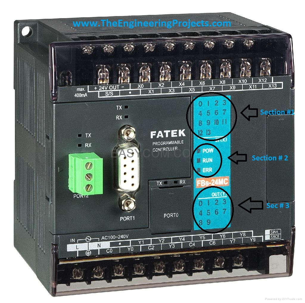
I think now you have the idea about PLC, so now I am getting started with PLC. I am gonna explain the functioning of Fatek PLC as I have used that one but if you are using another model of PC then no need to panic as all PLCs have same functionality. So, it doesn't matter which one you are using. If you check the below image then you will see I have marked three sections in it.
- Section 1 is indicating the status of input pins. If inputs are off then this section will remain as shown in above figure, but if any of the inputs get high, then the respective pin indicator will also glow into red, which indicates that this pin is ON. It helps while you are writing programming code for the PLC.
- Section 2 indicates the status of PLC. If PLC is powered up then the POW led will go red, if you have uploaded the code in PLC and start it then the RUN led will go red and if your code has some error then ERR led will go red.
- Section 3 indicates the status of output pins, it will tell you which output is currently ON.
In the below image, I have indicated Section 4 and 5, these are the input/ output section. If you have a look at it closely then you can see there are two rows of screws, where you plug your wires for inputs and outputs and above them, they are also labelled with white color. So, it goes like that, first row of labelling is for first row of screws and second row is for second row of screws.
- Section 4 is the inputs pins section, so if you check above there are inputs from X0 to X13, which makes it overall 14 inputs. Moreover, there are two pins labelled as + 24V and - 24V, which PLC is providing us, so if you wanna give any input to this PLC you have to make sure that its 24V, otherwise PLC not gonna recognize it.
- Section 5 is the output pins section. and you can see there are total 9 outputs starting from Y0 to Y8, now you are getting confused with C0 to C6. C pins are actually the voltage setter, let me explain, in projects there are different outputs are required like your motor is running at 12V DC while your solenoid valve is running at 220VAC. So, there's a need to set these voltages at the output. Here C pins are used. Suppose you need to give 12V output at Y0 and Y1 then give this 12V at C0 and when Y0 or Y1 is ON then they will give 12V at output. In short, when output gets ON it is actually connecting with their respective C pin.
- Lastly, check the Port 0 in the above image, this is the port where you plug your serial wire inPLC and connect it with your computer in order to upload the programming code.
That's all for today. I hope you got the basic idea of Programmable logic controller and now its time to have a look at Introduction to Ladder Logic for P L C, ladder logic is programming language for PLC. Your feedback are warmly welcome. In the next tutorial, I am gonna cover about ladder logic and will show you how to program a PLC. Till then Take care and have fun.