Installing PLC Simulator for Ladder Logic Programming
Hello friends, I hope you are doing very well! In today's tutorial, we will set up a simulation environment for Ladder Logic Programming. It's our second tutorial in Ladder Logic Programming Series. In our previous tutorial, we have seen a detailed Introduction to Ladder Logic Programming and we have seen that this programming language is used for PLC controllers.
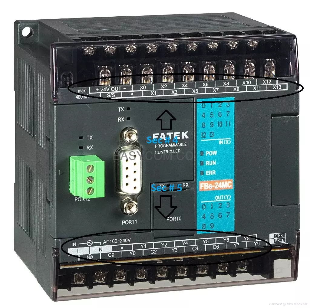
As PLC is an Industrial Controller, it comes with built-in relays/transistors(with protection circuitry) and thus is quite expensive as compared to microcontrollers/microprocessors i.e. Arduino, Raspberry Pi etc. Moreover, if you are working on a real PLC, you need to do some wiring in order to operate it. So, in order to avoid these PLC issues at the beginning, instead of buying a PLC one should work on a PLC Simulator. Using PLC Simulator, we can program our PLC controller and imitate its real behavior without having the hardware, saving both time and money as now we don't need to buy a new PLC and can start right away.
To sum up, by completing this article you will have a complete lab that includes the software you are going to use, the simulator that plays as the hardware, and certainly, you will be familiar with installing a PLC programming environment by which you can program, configure, moving the program to the PLC hardware, retrieving the program from the PLC to the software environment, and testing your program on the simulator. In addition, we are going to test our environment setup with a very basic program and take the chance to show you how to program, configure, upload, and test your program on the simulator.
Setup PLC Simulator
As I mentioned in the last tutorial, we are going to work on Siemens PLC throughout this tutorial, as it's one of the most common PLC controllers. So, we are going to install PLC Environment designed by Siemens and is called Total integrated automation (TIA). Along with this software, we will also need to install a PLC Simulator called S7 PLCSIM, again designed by Siemens. At the time of this writing, their most stable versions are 15.1, so download these two applications from below links:
Installing TIA Software
After downloading the TIA and the simulator, we extract the package by double click on the file we downloaded, and then it will be self-extracted and initiate the setup wizard as shown in the below figure. The image shows many steps. Moving our eyes from left to right, on the first part, the downloaded package has been extracted. In the next part of the picture in the middle, the setup wizard gets started by general settings in which you can set the preferred language and select the preferred installation location. The third part shows the setup goes on progressively and takes you to the end of the installation of the software IDE. Congratulation! You know have the programming software IDE installed on your computer and the good news is, all packages of Siemens go with the same scenario, you download the software package files. Click them to be extracted. And then, the installation wizard is launched by the end of file extraction which is a very systematic and easy way.
Figure 2: TIA portal version 15.1 setup wizard
Installing the PLC simulator
Well done so far! After having the programming software IDE completed, the next step is to install the simulator package which is PLCSIM version 15.1. Download PLCSim from the above link and then double-click the downloaded file of the simulator package as shown in Figure 3 to start extracting the packed file. You will be asked for the language and the location you prefer to have the installation folder. So you can leave it as the default or go with your preferences.
Figure 3: PLC simulator PLCSIM version 15.1 package extraction
After file extraction has been completed, the setup wizard will start automatically as shown in Figure 4 with the general setting screen by which you can set the preferred language and the location to install the simulator software. So you can use the default setting or update with your preferred choices.
Figure 4: the simulator setup general settings
Figure 5 shows the simulator setup configurations screen which helps you to configure and customize your installation. In this configuration screen, you can go with the typical options of installation in which all software components are selected to be installed or you can customize your installation to select or deselect components of the package. And by hitting the next button of this window, the installation will go on as shown in figure 6 until the end of the installation. During the installation progress, Siemens show off the features you may find in the software and the facilities you will enjoy by using this software. At the end of the installation, the wizard will request you to restart your computer now or later for completing the setup wizard by saving settings and registry values related to the installed software as shown in figure 7. That’s great! As for now, you have everything is ready and you are all set to get started and enjoy practice and learning the ladder logic programming and simulating your work.
Figure 5: the simulator setup configurations
Figure 6: the simulator installation screen
Figure 7: Simulator setup completion screen
Checking the setup environment
Before going any further let us check the successfulness of the installation process of the software and PLC simulator. Simply go to start and open TIA portal 15 and S7-PLCSIM you will see the software opening with no problem as shown in Figures 8 and 9. In figure 8, you can see options to create a new project or open an existing project. Also, there is an option to migrate projects from one version to another version by upgrading or downgrading the version of the projects. In addition, you can enjoy the welcome tour to know about the software programming tools and be familiar with its components. In addition, there is an option to check the installed software to validate the packages you select to include within your installation. for any further information you can click help to search and inquiry about any doubts.
Figure 8: Opening the TIA 15 software for testing installation successfulness
Moving to the S7 PLCSIM simulator software, as you can see in Figure 9, it is a very smart and simple interface. It shows a power button by clicking it you can shutdown the PLC controller or turn it on. Also, all indicators like the real PLC controller are included. You can see the RUN/STOP indicator. In addition, the ERROR indicator blinks red for any faults with the CPU of the PLC. In addition, you can see the run and stop buttons to start and stop the controller. Also, the MRES button to reset the PLC to the default values at any time. In addition, there is a detailed interface of the S7 PLCSIM simulator as shown in Figure 10. You can launch the detailed or maximized interface of the simulator by hitting the top-right icon on the shortcut window version of the simulator.
Figure 9: Opening the PLC simulator PLCSIM 15 for testing installation successfulness
The shortcut or the small version of the simulator shows the basic functions of the simulator like starting and stopping the controller or resetting the PLC and showing the status of the controller i.e. Run, stop, in fault status. But, the maximized or the detailed window simulator interface shows more options and facilities of the simulator. For example, you can create a simulation project to link it with a PLC project. Showing status of all input and output channels on the Input and output modules. In addition, it enables you to set and reset any of the inputs as we will elaborate in detail later in the next articles.
Figure 10: Opening the PLC simulator PLCSIM 15 in detail mode
Validating the PLC Simulator
After completing the installation successfully of the programming tools software TIA version 15.1 and the simulator PLCSIM version 15.1, it should be validated to make sure all components are installed and working properly. Let us validate by going through the functions and wizard. You now get in the Lab by opening the TIA portal and hitting create a new project as shown in Figure 11. On the right, you just need to name your project like for example let it be “first_ladder_prog” and you may leave the default location of projects or alter the data to the project file location as you prefer.
Figure 11: Creating a new project on the TIA portal
By hitting create, the creating project wizard comes out as shown in figure 12. As you can see you have many options to do on this screen like configuring the hardware, designing visualizations by designing and programming a human-machine interface (HMI) screen, motion control, or writing a ladder logic program. As for now do not worry about all these options as they are all not our scope in this series except those are relating to ladder logic programming like writing program option and configuring PLC device and network which we will come to them later in the next articles. For testing the installed software, you can simply select write a plc program for now.
Figure 12: creating project wizard
By choosing to write a PLC program, the wizard takes us to add the controller on which we are going to run the designed program as shown in Figure 13. If you are not familiar with the type of PLC controller models and hardware for now. That is not an issue because we are here to learn Ladder logic programming which is general for most PLC controllers of all brands i.e. Siemens, Schneider, Rockwell Automation, Allen Bradley, Beckhoff, WAGO, et cetera. So, for now, let us for testing purposes select S7-1200 which is one of Siemens PLC controllers to use in our project. By hitting the yellow small cross icon to add a device. You will see the list of the Siemens controllers that have appeared. For each controller, you can see many versions. Each version represents firmware for example, by selecting S7-1200 CPU 1211C AC/DC/RLY, you will see three versions. Each version represents a specific controller CPU in the market i.e. the selected one if of firmware ver 4.2 as shown in figure 14. By seeing this long list of CPUs and models, that means the software has been installed successfully and is ready to be used in our projects. So congratulation for successfully setting up the working environment for our Lab of ladder logic programming and being ready for utilizing this environment including programming software TIA 15.1 and simulator S7 PLCSIM version 15.1 in our learning and practice.
Figure 13: adding PLC controller wizard
Figure 14: selecting S7-1200 CPU v4.2
What’s next?
We are now all set to write our first ladder program on the TIA software and enjoy simulating our work on the S7 PLCSIM. In our next tutorial, we will write our first ladder logic program on the PLC simulator. Thanks for reading.
Introduction to Ladder Logic Programming Series
Hello friends, I hope you all are fine. Today, we are starting a new tutorials series on Ladder Logic Programming, used in PLC. It's our first tutorial in this series, so we are going to have a look at the detailed introduction to PLC and ladder logic. After welcoming every one of engineers, technicians, students, and hobbyists who have come to read this article willing to learn PLC programming, I would like to introduce one of the most used programming languages of PLC. The language we introduce here is a visualized language that connects and combines graphical symbols in logical flow same as the way we wire electrical circuits and that is the secret behind its simplicity not only in implementation but also in diagnosing problems.
Ladder Logic Programming has been derived from relay logic electrical circuits. This language of PLC programming is called ladder logic or LD as it looks like a ladder of many rungs. Each rung represents a line of logic by connecting inputs logically to form a condition on which the output is determined to be on or off. By completing this article, you will have enjoyed understanding the basics of the LD programming language. Consequently, you will have been able to read a ladder logic code and translate the logic in your mind or the electrical circuit between your hand into ladder rungs.
Relay Logic Control vs PLC
Relay logic control was the old fashion classic control in which input switches and sensors are connected between the hot voltage and relays’ coils to energize these coils and in turn, activate their contacts and thereby connect or disconnect the actuators i.e., motors, lamps, valves etc. You cannot imagine how complicated that control was besides its limitation in functionalities. In addition, it has a huge number of wires and components to achieve a simple logic. Furthermore, there are no chances to change the logic or the sequence of operation without destroying, rebuilding, and rewiring everything from scratch. When it comes to troubleshooting and maintenance, you should be very patient and generous for your time and efforts to pay to keep tracking hundreds of wires and checking up a bunch of components to figure out the problem.
To image the difference between old fashion classic control and PLC, figure 1 shows the case of a very simple process that contains four motors, and four sensors that are connected via four relays and a timer for performing a very simple logic. Let’s say we need to run motor 1 at the start and after a while, we plan to run motor 2 and 4, and at last run motor 3 considering one constraint that no more than two motors can run simultaneously. In addition, sensors will be used as protection to emergency stop motors at any time. Now on the left of the figure, you can see the relay logic control. you can imagine how many components and punch of wiring work for connecting sensors, timers, relays, and motors. On the other hand, PLC-based control shown on the right, you can notice only the PLC and input devices and output actuators are connected to the PLC. To sum up, the number of wires is reduced significantly, the effort of wiring is immensely reduced. In addition, when it comes to modification of logic or process sequence you need to destroy all old wiring and start over rewiring according to the new requirements while you can do this by modifying the program in PLC without touching the wiring. To sum up, PLC reduced the number of components, wires, time of implementation. In addition, the processing is faster thanks to PLC processing and modification becomes programmatically.
How PLC works?
Before opening the door to enter our tutorial on ladder logic programming, let’s have a brief idea about how PLC works and what ladder logic program has to do with PLC. Well! Let me briefly say that PLC has input modules, output modules, and a processor. The input modules are connected to input switches and sensors while the output modules are connected to actuators i.e., motors, valves, lamps. And for sure processor runs the ladder logic program that we going to learn here! In the below figure, I have tried to clear it visually.
The processor works in scan cycles, in each scan cycle, it gazes into all inputs and records them in its memory and then executes the ladder logic to determine the new status of outputs and update them and go to the next cycle, and so on. So now you can tell me what ladder logic has to do with this? That is great to hear you say that it is the logical connection between inputs to determine the output status. I really can not wait to go ahead and hit the nails on the head and open the door to let us get started with our tutorial about ladder logic programming. In the below figure, I have shown PLCs of different manufacturers:
Ladder Logic Programming
Each programming language has a structure and building blocks. The building block of a ladder program is a rung. Yes, rungs of a ladder go step by step to do the designed logic and repeat every scan cycle. Each rung forms a complete piece of logic like one complete circuit. so let us go to know how to form this rung and get to know what components of these rungs and how they are connected logically.
Understanding Rung in Ladder Logic
- In the below figure, I have shown a single rung of ladder logic programming.
- It's the simplest ladder logic rung and it has Input on the left side and Output on the right side.
- The ladder logic rung is composed of two parts:
- The Left Part represents the condition on which the output is determined to be true or false. This part is a combination of contacts or inputs in series for making AND logic or in parallel to perform OR logic.
- The Right Part is the output coil or a trigger signal to start timer or counter as we going to elaborate later.
- Ladder Logic works from left to right and thus according to this rung, if Input is LOW, the output will remain LOW, and if Input gets HIGH, the Output will also get HIGH.
- So, you can say the above rung is actually representing a simple electrical switch i.e. if we turn ON the switch, Lamp(Output) will get lightened up and vice versa.
- In this tutorial, I am just giving the overview, so if you are not getting all the things, don't worry, as, in the upcoming tutorial, we will design them on the simulator again & again.
- Inputs in LAdder Logic PRogramming are normally coming from switches, pushbuttons, sensors etc.
- Inputs come in two configurations:
- Normally Open (NO): shows the input initially at a LOW state and gets HIGH by pressing or activating.
- Normally Closed (NC): It's initially is at a HIGH state and gets LOW when it is pressed.
Multiple Rungs in Ladder Logic
In the above section, we have designed a simple ladder logic program, where we have used just a single input to control our output. These contacts/inputs in their two configurations can be connected in series (AND logic), parallel (OR logic), or negation (NOT) to form logical combinations. In the below figure, I have designed three rungs of Ladder Logic, let's understand them one by one:
- 1st Rung: I have used two Normally Open Contacts in the first rung, so you can think of it as an electrical line having two switches in series. So, the output will get current, only if both switches are on/closed. So, it's actually an AND Gate in Ladder Logic i.e. output will get HIGH only if all the inputs are HIGH.
- 2nd Rung: In the second rung, I have used both normally open and normally close contacts, so if Input1 gets pressed, the output will get HIGH, but if Input2 gets pressed(actually open/off) then Input1 won't be able to turn ON the Output. So, you can think of Input2 as a master switch.
- 3rd Rung: Now you must have understood by now that I have designed an OR Gate in this rung, so if any of these inputs get HIGH, the Output will get HIGH as well, because Inputs are connected in parallel.
Note:
- When two or more inputs are connected in parallel in order to design OR logic, it's called rung branches.
Slightly Complex Project in Ladder Logic
In the below figure, you can see a slightly complex Ladder Logic Program, having different components, let's discuss them one by one:
- The output coil may have the character “S” to show the output going to be set to true until a reset signal is received.
- Furthermore, it could have the character “R” to show the reset status of the output to false.
- Character “P” in the middle of contact shows this is the rising edge of input when it changes from false status to true.
- On the other hand, character “N” in the center of contact shows the falling edge of the input when it changes from true to false.
- And the timer and counter blocks are shown in the last two rungs to show the initiation of timer and counter.
- All these components will be described in detail when the tutorial train reaches its station. So do not worry about them at this point.
Logic Gates & Ladder Logic
If we define the ladder and its building blocks which are rungs how about the word “logic” the second word in ladder logic? Well! Table 1 reviews the logic gates and their truth table. For you to expect the incoming status of your output based on the status of the inputs and the logical combination pattern. to decide the results logic output ( RLO) which is the status of the logical combination of contacts that precede the output coil. For instance, the AND gate/logic function is applied between two or more inputs when all of the inputs should be true to get the output to be true. On the other hand, the OR gate/logic function between two or more inputs is used when we need at least one of the inputs to be true to get the output to be true.
Reading ladder logic rung
- The reading starts from left to right to complete one rung and then from up to down rung by rung till the end of the program.
- You can imagine that you read the ladder program instead of PLC.
- First, you scanned the input and update the input memory and then scan each rung from most left to right to evaluate the RLO and set the new status of the output based on the determined RLO.
- After completing one rung, plc move to the next rung from top to bottom till the last rung in the program at that point one scan cycle is done and move to the next scan cycle and so on.
- You can compare Ladder Logic with electrical wiring logic, as both follow the same pattern.
Let’s see one simple example to understand the reading ladder logic program. Figure 3 shows a very simple complete ladder logic rung that connects a normally open pushbutton to start a motor and another normally closed pushbutton to stop the motor. You can see each component of the inputs and outputs should have an address to be uniquely identified by PLC. For instance:
- The normally open push button named “Run” takes an address of I0.0 which is linked to the first input channel of the first input module in PLC.
- The normally closed push button to stop the motor called “stop” takes the address I0.1 which is physically connected to channel 2 in the first input module of the PLC.
- On the other hand, the output coil takes address Q0.0 which is the first output channel of the first output module in PLC.
- So clearly when you press your push button "RUN" it will connect the motor output coil to the positive line and hence get energized.
- But when press the "STOP" button, you will disconnect the motor coil from electricity and hence stop it.
What’s next ???
Now, how do you see your progress so far? I can see you are doing progressively and that’s great. However, we still have a lot to learn to master ladder logic programming. However, we need to set up the environment for simulating a Ladder logic program to be able to validate our programs and enjoy seeing its execution typically as if we have a PLC controller and to verify how far our designed ladder performance matches the real-time execution on the simulator.
Logical Gates in Ladder Logic for PLC
In the previous post Logical Gates in Ladder Logic for PLC, we had an overview of what is Ladder Logic programming and we have also implemented three basic Logical gates in Ladder Logic form. Today, we are gonna have a look at some complex Logical Gates in Ladder Logic for PLC. So, I hope till now you guys have basic knowledge of Ladder Logic and can implement complex logical gates in it. If you haven't read the previous post then must read because without that knowledge you won't understand this post.
In today's post we are gonna implement few complex logical gates. Its not gonna be much difficult if you have the basic concepts. I am just pointing out few important points here. While implementing any gate in ladder logic, always consider rung as an electrical line having HIGH voltage at one end and LOW voltage at the other, while the inputs are simple switches. Voltage will be supplied to the output only when switch is closed i.e. input is HIGH, otherwise the output will remain OFF. You should also have a look at Introduction to Logic Gates.
You have seen in previous post, while implementing OR gate we have used a second switch in parallel which ends at the first rung so overall its a single rung having two inputs in parallel so input can come either from first switch or from second one. So, now let's start implementing some complex logical gates in Ladder Logic for PLC. Today, we are gonna implement these logic gates:
- NAND Logical gate in Ladder Logic for PLC
- NOR Logical gate in Ladder Logic for PLC
- XOR Logical gate in Ladder Logic for PLC
- XNOR Logical gate in Ladder Logic for PLC
NAND Logical gate in Ladder Logic for PLC
- NAND gate is another type of logical gate, which is normally used. NAND gate is nothing but a simple NOT of AND gate. In simple words, if we add a NOT gate in front of AND gate, we get NAND gate. The truth tablel of NAND gate is shown in the below figure:
- It is quite obvious from the truth table of NAND gate that the output will be OFF only when both the inputs will be ON otherwise output will remain ON. So, now lets implement this gate in ladder logic programming.
- The below image shows the implementation of NAND logical gate in Ladder Logic form:
- Now, if you understand the above figure, then its quite obvious. We have used both inputs in normally closed form so when both inputs are OFF the output will be ON. If we get X0 ON then in still we will get the HIGH voltage from X1. If we make X1 ON then we get HIGH voltage from X0, but if we get both X0 and X1 ON then our Y0 will get OFF. Again we are using inputs in normally closed form so when our actual input is OFF then our X0 is closed. :)
NOR Logical gate in Ladder Logic for PLC
- In NOR gate, we simple place a NOT gate in front of OR gate. Its truth table is shown in below figure:
- From the truth taable of NOR gate, its quite obvious that its output will be ON when both of its input goes OFF otherwise the output will remain ON. Lets implement this NOR logical gate in Ladder Logic diagram.
- The below figure shows the NOR logical gate in ladder logic diagram:
- If you got the ladder logic form of NAND gate, then its not gonna be much problem. Simple two normally closed inputs are placed in series, so now when any of them gets ON, then output will get OFF.
Note:
- If you have noticed, whenever NOT gate is involved somewhere, we use normally closed inputs.
XOR Logical gate in Ladder Logic for PLC
- The truth table of XOR gate is shown in below figure:
- From the truth table, we can get this thing that, output will ON only when the inputs are in opposite states and output will be OFF when inputs are in same state.
- The ladder logic implementation of XOR gate is shown in below figure:
- Now it has gone a little complex but lets understand how's its working. We have placed X0 and X1 in series and also in parallel, but in first string X0 is normally open and X1 is normally closed while in second string X0 is normally closed and X1 is normally open.
- Now, what we need to do is if both inputs are in same state we need to turn OFF the output. That's what we are doing in above logic diagram. Let's say X0 and X1 both are OFF then the normally open switches will be OFF and they wont let the HIGH voltage pass and hence our Y0 will remain OFF. And if both are ON then the normally closed will be OFF and again Y0 will remain OFF.
- Now if X0 is ON and X1 is OFF, then the first string will connect and our output will ON, and if X0 is OFF while X1 is ON then our second string will connect and will make our output ON. Quite simple and easy.
XNOR Logical gate in Ladder Logic for PLC
- Last but not the least XNOR gate, if we add NOT gate in front of XOR gate we get XNOR gate, let's have a look at its truth table below:
- So, in XNOR gate, we get our output ON when both inputs are in same state otherwise its OFF. Let's implement it in ladder logic form below:
- Now in this ladder logic diagram, we are getting introduced with a new symbol, till now we have used normally open output but here for the first time, we are using normally closed output Y0.
- It's exactly the same logic as we used for XOR gate, but the only difference is ere we are using normally closed output. So, simple when the output is gets ON, its actually OFF and when it gets OFF its actually ON ;)
- I hope now you got the clear concept of How to do programming using Ladder Logic and what's its difference with Microcontrollers like Arduino or PIC Microcontroller etc.
That's all for today, hope I have conveyed some knowledge. If you are new to PLC programming then you won't get it in the first attempt so my suggestion is give it some time, read it again and again and you will feel better :) I am not gonna post more about Ladder Logic designing, instead in the next post we are gonna have n overview of PLC simulation software in which we design this ladder logic diagrams. Till then take care and have fun :)
Introduction to Ladder Logic for PLC
Hello everyone, I hope you all are doing great. In today's tutorial, I am going to share the detailed fIn the previous post, we have seen Introduction to PLC, which was quite simple and has the basic introduction to PLC. To day we are gonna have a look at Getting Started With Ladder Logic For PLC. Ladder Logic, also named as Ladder Logic Programming, is the programming language for PLCs. Its normally considered as the most difficult language among the engineers because of its complex structure, but if you ask me then I will say its the most interesting programming language.
Ladder Logic is different from the usual programming language of Microcontrollers like Arduino, PIC Microcontroller etc. Microcontrollers programming usually compiled from top to bottom i.e. the compiler first capture the first statement and then moves downward till it reaches the end line but that's not the case with Ladder Logic Programming for PLC. In ladder logic, the compiler moves from left to right and it gets all the lines at the same time. It seems bit difficult to understand at first but be with me and you will get it at the end. :)
Introduction to Ladder Logic
Ladder Logic is a programming language used for PLC as C for Microcontrollers. Ladder logic is a combination of rungs. Each rung is executed from left to right. For example, have a look at the below figure, a single rung of ladder logic is shown in it.
- In the above figure, a single rung of ladder logic is shown. Now as I mentioned earlier, each rung is executed from left to right, so the above rung will also do the same behavior.
- There are two symbols mentioned in the above rung, one is X0 and the other is Y0. X0 is placed on the left side while Y0 is placed on the right side.
- We have seen in our previous tutorial Introduction to PLC, that X always indicates input and Y indicate output, so in short the above rung has input on the left side while output on the right side.
- So combining all the above discussion, we come to the conclusion that input will be executed first and then output will be executed, as shown below. (I hope you got the basic theory now :) )
- So now the thing is, if we only consider the above rung, the output Y0 will be ON only if input X0 will be ON. If X0 is OFF then Y0 will also be OFF. Consider this rung as a voltage wire as shown in below figure:
- So, now the output will be ON only when it has HIGH and LOW but input is acting as a switch and in normal condition, its OFF so HIGH is not reaching to output so it will remain OFF, as we turn ON the input X0, it will be like the switch is closed and HIGH will pass through the X0 and will reach Y0 and Y0 will turn ON. I tried my best to explain it as simple as I can but still having confusion, ask in comments.
- Now let's have a look on different logical gates i.e. AND gate, OR gate, NAND gate etc, we normally create in ladder logic.
1. Logical AND in Ladder Logic for PLC
- We all know about the Logical AND gate, in AND gate we get output only if both the inputs are HIGH, otherwise OUTPUT remain OFF.
- The below figure shows the same logical AND gate designed in Ladder Logic diagram:
- Now in the above figure Y0 will be ON when both X0 and X1 are ON, otherwise Y0 will be ON, again consider inputs as switches.
- Its a simple 2 input AND logic, we can add as many inputs as we want in it. For example, below image shows a four input AND gate.
2. Logical OR in Ladder Logic for PLC
- In Logical OR gate, output goes ON when any of the inputs is ON, lets implement it in our ladder logic form.
- The below figure shows the ladder logic form for OR gate:
- If you check the above figure, if X1 goes ON then our connection will connect and Y0 will be ON, similarly, if X0 is OFF and X1 is ON then again Y0 will be ON because now voltage is coming from X1. Again consider inputs as switch.
3. Logical NOT in Ladder Logic for PLC
- In logical NOT gate, output is always opposite to input, if input is HIGH then output will be LOW and vice versa.
- In order to implement NOT gate, we have to consider another type of input, the input which we are using till now is normally open input, means it is open (OFF) in its normal condition and gets closed (ON) when input is supplied, but in ladder logic there's another type of input also present named as normally closed input.
- Normally closed input is closed (ON) in its normal condition and goes open (OFF) when it gets actual input.
- So, using this normally closed input, we can quite easily implement this Logical NOT gate in ladder logic as shown in below figure:
- In the above figure X0 will be ON in normal condition and hence, Y0 will also be ON and when we get actual input then X0 will get OFF and our Y0 will also be OFF.
So, that was all for today. As you have got the basic knowledge of Ladder Logic, so now its time to have a look at How to design
Logical Gates in Ladder Logics for PLC. Thanks for reading. :)
Introduction to PLC
Hello friends, I hope you all are fine and enjoying good health. Today's tutorial, as the name shows, is on Introduction to PLC. PLC is an abbreviation of Programmable Logic Controller. Recently I worked on a project in which I have to design a Automated coffee Mixing Machine Using PLC. It worked quite good and I had a great time while working on it. After completing that project, it occurred to me that I haven't posted any tutorial on PLC. So I thought of starting this tutorial. This tutorial is not gonna cover in single post so my plan is to divide it in parts.
Today. I am gonna give an overview about PLC. We will have a look on basics i.e. what is PLC? Why we use PLC instead of microcontroller like Arduino or PIC Microcontroller? What's its advantages and disadvantages? I will try to cover all about the basics. After reading this tutorial, you must have a look at Introduction to Ladder Logic for P L C, Ladder Logic is programming language for PLCs.
There are different types of PLCs available in the market manufactured by different companies, so its impossible to cover all of them. In this tutorial, I am gonna discuss Fatek PLC as I have worked on it during my project. The model I have used is Fatek PLC Fbs-20MA. The reason I used this model because it was cheap and has enough input/output ports sufficient for my project. That's why I preferred it as its engineers' task to optimize the cost as well. Let's get started with PLC.
What is PLC?
Its a basic question, which is normally asked by all the starters so I am gonna reply it first for the newbies.
- PLC is nothing but an advanced form of Microcontroller. It is usually used in industries because of its flexibility and ease of use.
- It can be attached quite easily with computer via serial port as well as usb port.
- PLC is used when we need to automate anything just like microcontroller. We attach our sensors and actuators etc with PLC and then insert some programming code in it and let it do its job.
- You have seen automated lifts, they all are operated with PLC.
- We can use timers, counters, registers in PLC and can get any kind of output from it.
- We can program PLC with different languages and the most commonly used language for PLC is named as Ladder Logic.
Internal Overview of PLC
What's inside PLC, which makes it so cool ? That's a good question and normally engineers wonder about it. PLC can be divided into 3 sections, which are as follows:
- Power Supply - Thissection provides power to the PLC, in my case it is operated on 220V AC, so when I provide 220V AC to my PLC, it got activated and start performing functions.
- Centeral Processing Unit (CPU) - Its the actual brain of PLC, it is further divided into several parts i.e. RAM, ROM, EEPROM, microcontroller etc. The programming code is uploaded in this CPU and according to that program, it performs its functions.
- Input / Output Section - This section is the one from where PLC communicates with the external world. We can attach sensors to the inputs of PLC and can operate our motors, actuators etc from the outputs of PLC.
Types of PLCs
- There are different types of PLCs available in the market manufactured by different companies.
- Few famous PLC companies are Siemens, Mitsubishi, Fatek etc.
- Moreover, they are also available in different sizes and functions. The one I used has 14 inputs and 8 outputs. It doesn't support analog inputs as I don't require them.
- There are PLCs available with analog inputs or you can also buy cards which are interfaced with the PLC and make them capable to work on analog inputs.
- Another function which is not available in my PLC is the Serial communication, but such models are available which supports serial communication.
- So in short, there are several models of PLC available in the market and you have to consider your project demands while buying a PLC.
Why use PLC instead of microcontrollers?
- Microcontroller is normally used in small products, where you need to control some sensors or some motors etc but when we talk about big automated plants in industries then PLC is always preferred over microcontroller.
- The reason for preferring PLC over microcontroller in big projects is because of its flexibilty and ease of use. PLC can be programmed frequently with computer, suppose you have an automated system and you find some bug in it which you wanna remove, then what you need to do is simply attach a computer with the PLC of that plant and make changes in the code, which isn't possible with the microcontroller.
- Moreover, PLC has lot of memory, you can add any size of data in it.
- PLC is also long life as compared to microcontroller.
- Last but not the least, PLC has built in cards to control heavy AC voltages, you can get any kind of voltage from PLC i.e. 220V AC etc but if you wanna get such voltages from microcontrollers then you have to add some extra circuitry.
- In short, in all industrial automated plants, PLC is used.
Getting Started With PLC
I think now you have the idea about PLC, so now I am getting started with PLC. I am gonna explain the functioning of Fatek PLC as I have used that one but if you are using another model of PC then no need to panic as all PLCs have same functionality. So, it doesn't matter which one you are using. If you check the below image then you will see I have marked three sections in it.
- Section 1 is indicating the status of input pins. If inputs are off then this section will remain as shown in above figure, but if any of the inputs get high, then the respective pin indicator will also glow into red, which indicates that this pin is ON. It helps while you are writing programming code for the PLC.
- Section 2 indicates the status of PLC. If PLC is powered up then the POW led will go red, if you have uploaded the code in PLC and start it then the RUN led will go red and if your code has some error then ERR led will go red.
- Section 3 indicates the status of output pins, it will tell you which output is currently ON.
In the below image, I have indicated Section 4 and 5, these are the input/ output section. If you have a look at it closely then you can see there are two rows of screws, where you plug your wires for inputs and outputs and above them, they are also labelled with white color. So, it goes like that, first row of labelling is for first row of screws and second row is for second row of screws.
- Section 4 is the inputs pins section, so if you check above there are inputs from X0 to X13, which makes it overall 14 inputs. Moreover, there are two pins labelled as + 24V and - 24V, which PLC is providing us, so if you wanna give any input to this PLC you have to make sure that its 24V, otherwise PLC not gonna recognize it.
- Section 5 is the output pins section. and you can see there are total 9 outputs starting from Y0 to Y8, now you are getting confused with C0 to C6. C pins are actually the voltage setter, let me explain, in projects there are different outputs are required like your motor is running at 12V DC while your solenoid valve is running at 220VAC. So, there's a need to set these voltages at the output. Here C pins are used. Suppose you need to give 12V output at Y0 and Y1 then give this 12V at C0 and when Y0 or Y1 is ON then they will give 12V at output. In short, when output gets ON it is actually connecting with their respective C pin.
- Lastly, check the Port 0 in the above image, this is the port where you plug your serial wire inPLC and connect it with your computer in order to upload the programming code.
That's all for today. I hope you got the basic idea of Programmable logic controller and now its time to have a look at Introduction to Ladder Logic for P L C, ladder logic is programming language for PLC. Your feedback are warmly welcome. In the next tutorial, I am gonna cover about ladder logic and will show you how to program a PLC. Till then Take care and have fun.