 BETA
L293D Working Principle
Learn how L293D works with an illustrated explanation and practical readings.
L293D at a glance
Follow the labeled connections and functional stages
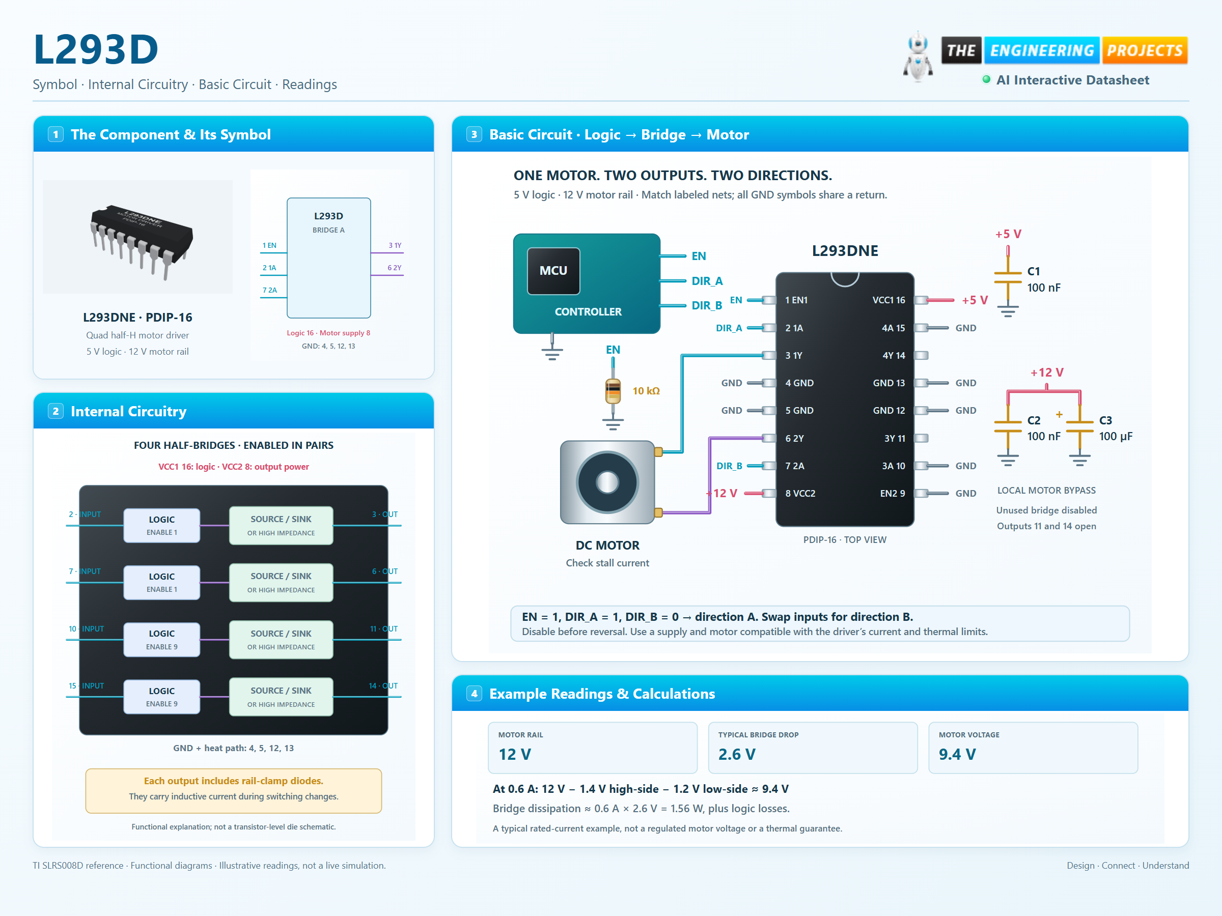
How it works
3 stages · Explore one step at a time
Enable one output pair
Set 1,2EN HIGH to make 1Y and 2Y follow their corresponding inputs. Disable the pair to release both motor leads into high impedance.
Reverse the motor voltage
Opposite input states apply opposite polarities across the motor. Swapping the inputs reverses the commanded direction.
Brake or coast deliberately
Equal enabled outputs short the motor terminals to the same rail for dynamic braking. Disabled outputs let the motor coast; stored inductive current still uses the clamp paths.
Direction, brake or coast?
Switch the inputs to explore one complete motor bridge.
Enable JavaScript to explore bridge control.
Logic-state explorer only. The colored motor indicates commanded direction, not simulated speed. Current, inertia, switching time, voltage drop, clamp transients and heating are not calculated.