 BETA
Supply and bypass
Feed pin 1 from 12 V and keep the input capacitor close to the switching-current loop.
Build a basic LM2596 circuit with labeled pins, component values and connection guidance.
Five physical leads, an energy-storage inductor and a catch diode.
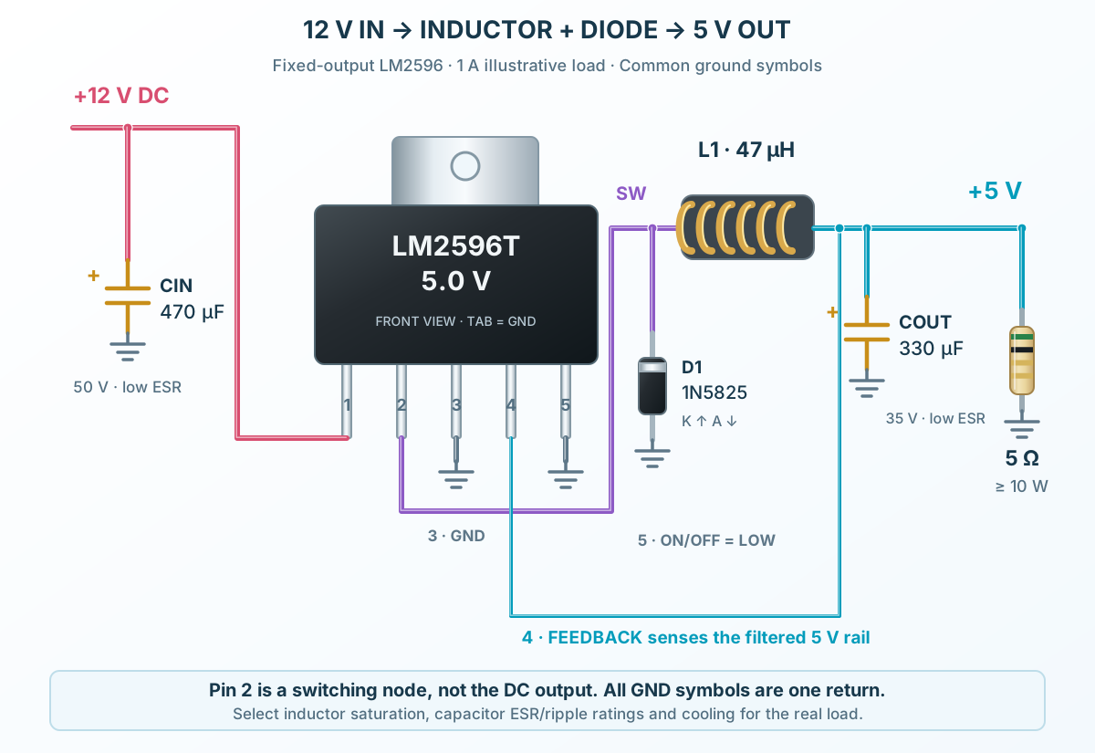
Follow the component values and pin connections
Feed pin 1 from 12 V and keep the input capacitor close to the switching-current loop.
Pin 2 feeds L1. D1 provides the OFF-state current path; its cathode is at the switch node.
Connect pin 4 after L1. Ground pin 5 for continuous operation and pin 3/tab for the common return.