 BETA
Connect input and return
Feed INPUT from 9 V DC; put 0.1 µF between this rail and the common return.
Build a basic LM317 circuit with labeled pins, component values and connection guidance.
One regulator, two resistors and short bypass connections.
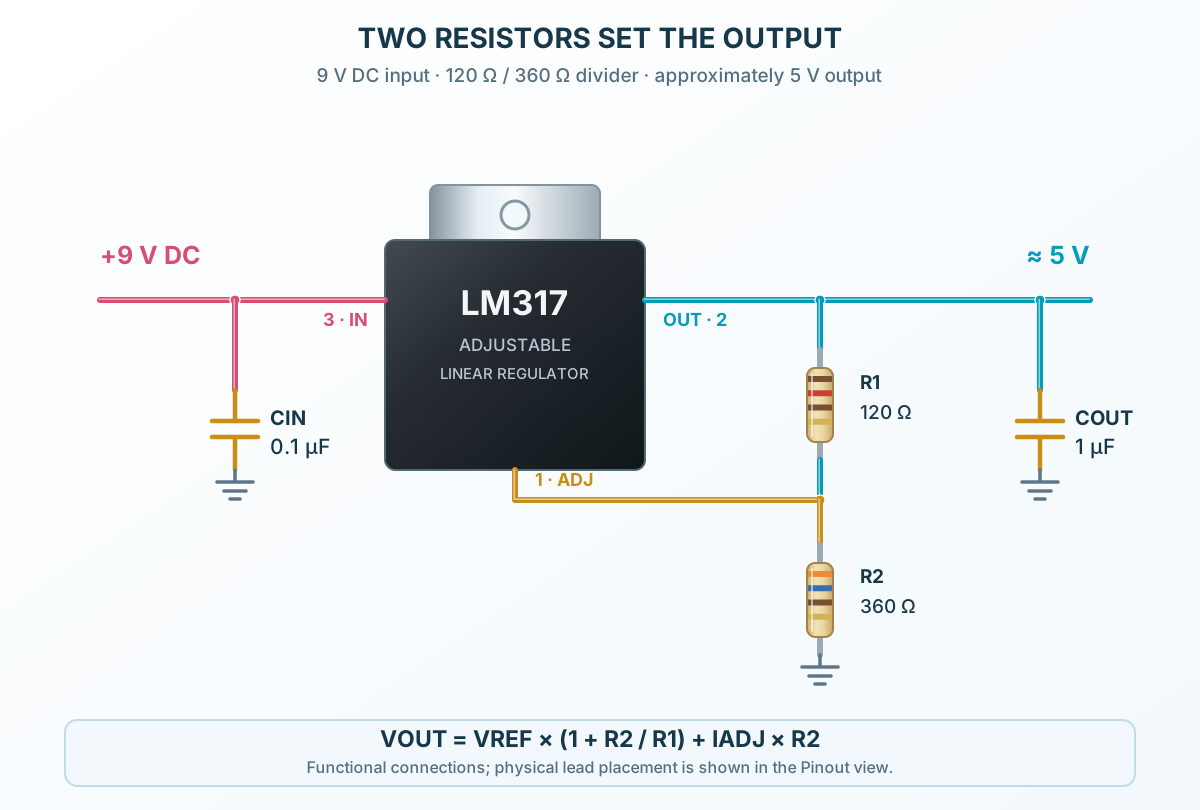
Follow the component values and pin connections
Feed INPUT from 9 V DC; put 0.1 µF between this rail and the common return.
R1 = 120 Ω goes from OUTPUT to ADJUST. R2 = 360 Ω goes from ADJUST to GND.
The ideal output is 5 V. Account for adjustment current and heating, then check it under the intended load.