 BETA
Adjustable linear regulator
LM317 Working Principle
Learn how LM317 works with an illustrated explanation and practical readings.
Package view
LM317 at a glance
Follow the labeled connections and functional stages
How it works
3 stages · Explore one step at a time
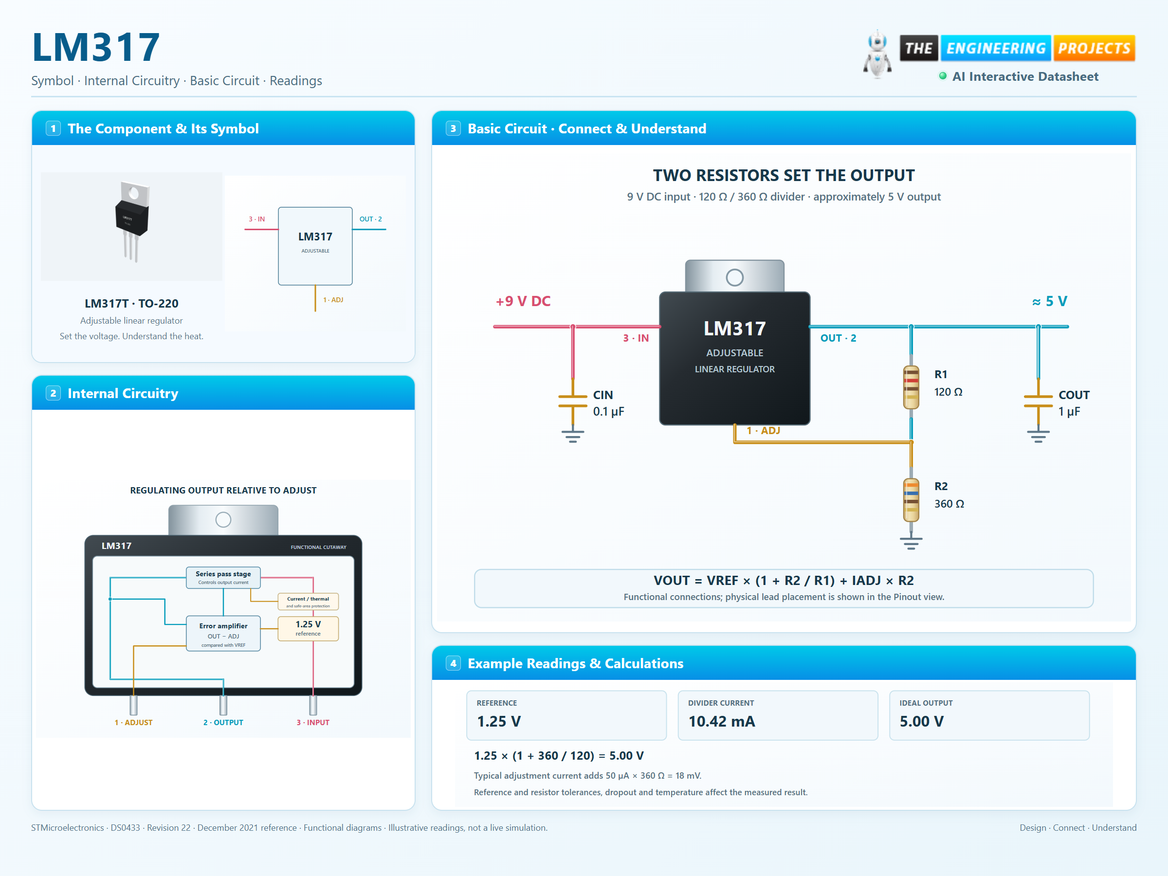
Create the reference
The regulator maintains approximately 1.25 V from OUTPUT to ADJUST. Unlike a 7805, the adjustment terminal is not tied directly to ground.
Set output with two resistors
R1 runs from OUTPUT to ADJUST; R2 runs from ADJUST to the return. Their ratio sets the output, with a small additional term from adjustment-pin current.
Keep the loop within its limits
The source must provide headroom and the load must draw sufficient current. Input-to-output voltage and current become heat in the pass stage.
Step 1 of 3