 BETA
LM339 Working Principle
Learn how LM339 works with an illustrated explanation and practical readings.
LM339 at a glance
Follow the labeled connections and functional stages
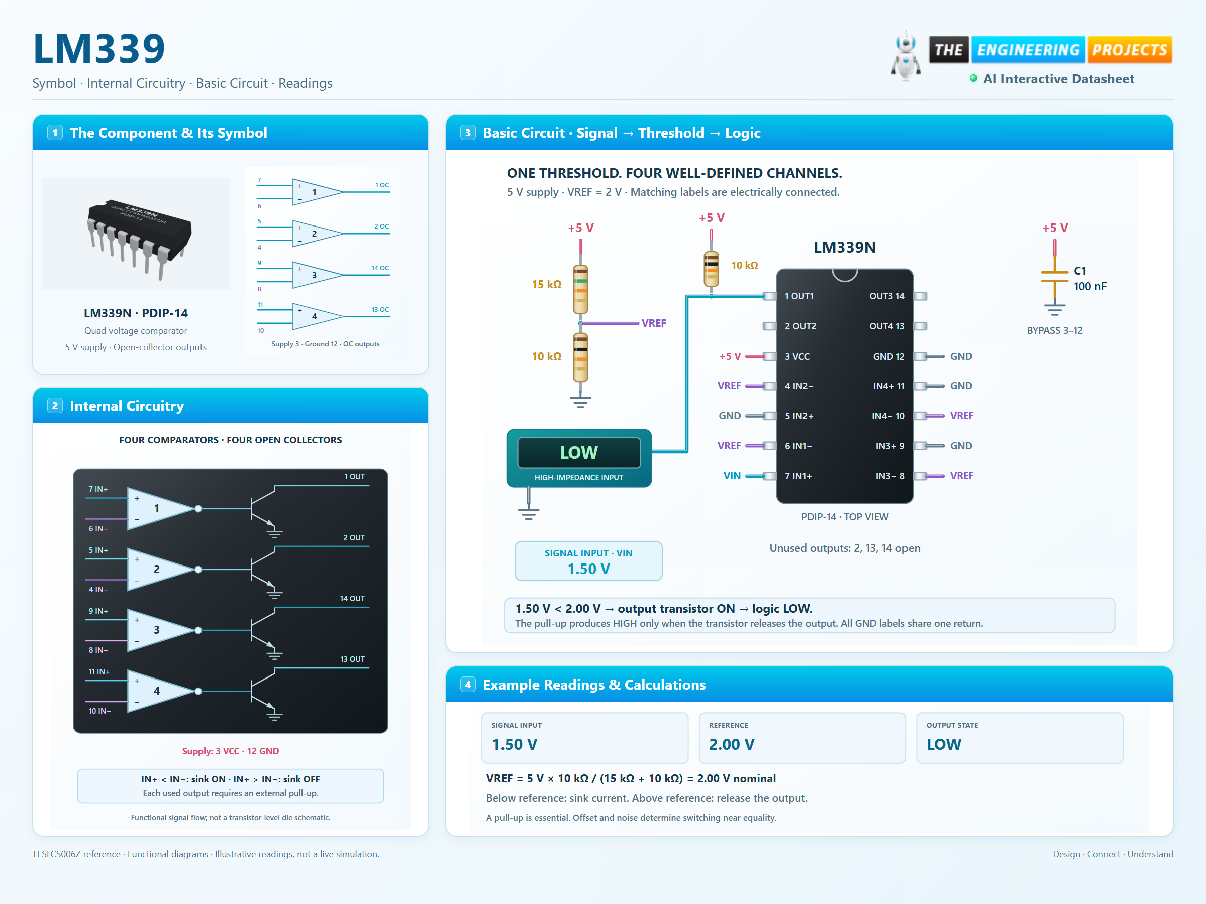
How it works
3 stages · Explore one step at a time
Compare the inputs
Each channel responds to IN+ minus IN−. A sufficiently positive difference releases its output; a negative difference turns the sink transistor on.
Let the pull-up set HIGH
An open collector cannot drive HIGH by itself. The pull-up supplies the output node when the transistor is off.
Keep a margin near equality
Offset and noise determine the state near the threshold. Add intentional hysteresis when a noisy signal would otherwise cause repeated switching.
Find the switching threshold
Adjust VIN and the reference. Remove the pull-up to see why it matters.
Enable JavaScript to explore the comparator.
Violet: offset-sensitive transition · Amber: input outside the recommended range.
DC teaching model for one classic LM339 channel. The ±9 mV region illustrates possible offset, not built-in hysteresis. A fixed 0.15 V LOW is illustrative; real output voltage depends on sink current and temperature. Timing and noise are not simulated.