Skip to datasheet
RS-232 transceiver

MAX232 Working Principle

Learn how MAX232 works with an illustrated explanation and practical readings.

Package view

MAX232 at a glance

Follow the labeled connections and functional stages

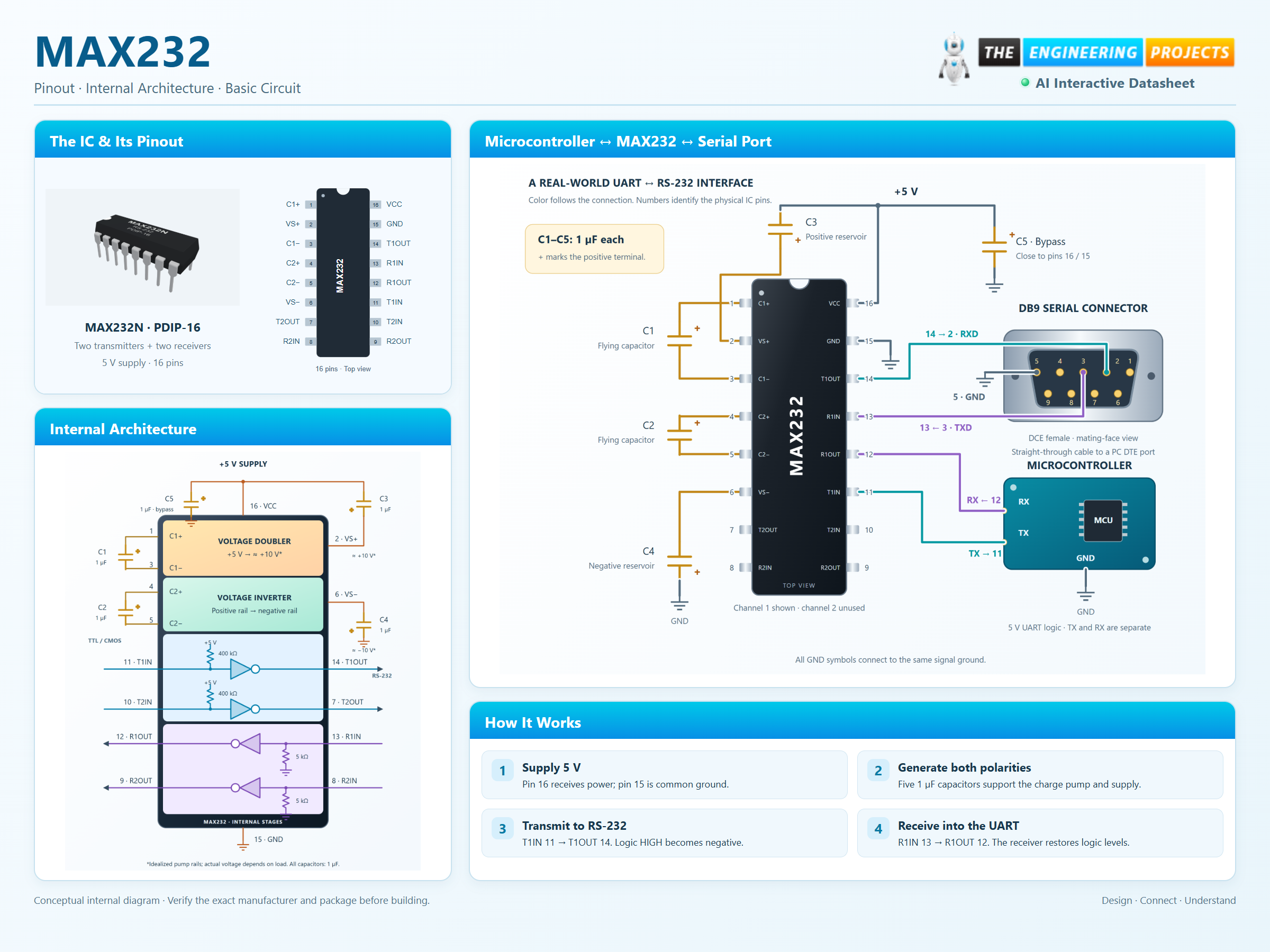
MAX232 working principle: illustrated functional stages, basic circuit and connections
Select the diagram to read it at full resolution.

How it works

5 stages · Explore one step at a time

Step 1 / 5

Two electrical languages

A microcontroller’s UART uses logic levels, while an RS-232 port uses positive and negative voltages. The MAX232 translates between them. It changes voltage levels and polarity; it does not create a baud rate or decode the data.

Step 2 / 5

Create the driver rails

Connect pin 16 to 5 V and pin 15 to ground. C1 transfers charge in the voltage doubler; C2 supports the inverter. C3 and C4 hold the positive and negative rails, and C5 bypasses the supply. This MAX232 circuit uses 1 µF for all five capacitors.

The diagram’s approximately ±10 V rails explain the unloaded charge-pump action. Actual rails and output swing depend on supply, load and losses.

Step 3 / 5

Transmit to RS-232

Microcontroller TX feeds T1IN, pin 11. T1OUT, pin 14, drives the serial line with an inverted bipolar signal: logic HIGH becomes a negative RS-232 voltage, and logic LOW becomes positive. Channel 2 works the same way through pins 10 and 7.

Step 4 / 5

Receive into the UART

The remote transmitter reaches R1IN, pin 13. The receiver converts the RS-232 signal into a logic output at R1OUT, pin 12, for the microcontroller’s RX input. A negative input gives logic HIGH; a positive input gives LOW. The second receiver uses pins 8 and 9.

Step 5 / 5

Complete the connection

The Basic Circuit shows a DCE female DB9 connector from its mating face: pin 2 carries the MAX232’s output, pin 3 accepts the PC’s transmit signal, and pin 5 is signal ground. A straight-through cable joins it to a PC DTE port. TX and RX operate independently, allowing two-way communication.

Follow the signal

Choose a channel, change its input and read the output polarity.

Interactive explanation

Transmitter 1

Converts the local logic output into an inverted bipolar RS-232 signal.

Input

T1IN · pin 11 · TTL / CMOS

HIGHLogic level
MAX232Inverting driver
Output

T1OUT · pin 14 · RS-232

NEGATIVERS-232 polarity

A HIGH logic input produces a negative RS-232 output. A LOW input produces a positive output.

Transmitter 2

A second independent transmit path, powered by the same internal charge pump.

Input

T2IN · pin 10 · TTL / CMOS

HIGHLogic level
MAX232Inverting driver
Output

T2OUT · pin 7 · RS-232

NEGATIVERS-232 polarity

A HIGH logic input produces a negative RS-232 output. A LOW input produces a positive output.

Receiver 1

Accepts an RS-232 line signal and provides an inverted logic-level output for the local UART.

Input

R1IN · pin 13 · RS-232

POSITIVERS-232 polarity
MAX232Inverting receiver
Output

R1OUT · pin 12 · TTL / CMOS

LOWLogic level

A positive RS-232 input produces a LOW logic output. A negative input produces a HIGH output.

Receiver 2

The second receive path works independently of receiver 1. Both use the common ground reference.

Input

R2IN · pin 8 · RS-232

POSITIVERS-232 polarity
MAX232Inverting receiver
Output

R2OUT · pin 9 · TTL / CMOS

LOWLogic level

A positive RS-232 input produces a LOW logic output. A negative input produces a HIGH output.

Illustrative steady-state levels, not a timing simulation. The traces show polarity, not measured voltage. Output swing depends on supply and load; receiver switching also has thresholds and hysteresis.

Component view