 BETA
MCP3008 Working Principle
Learn how MCP3008 works with an illustrated explanation and practical readings.
MCP3008 at a glance
Follow the labeled connections and functional stages
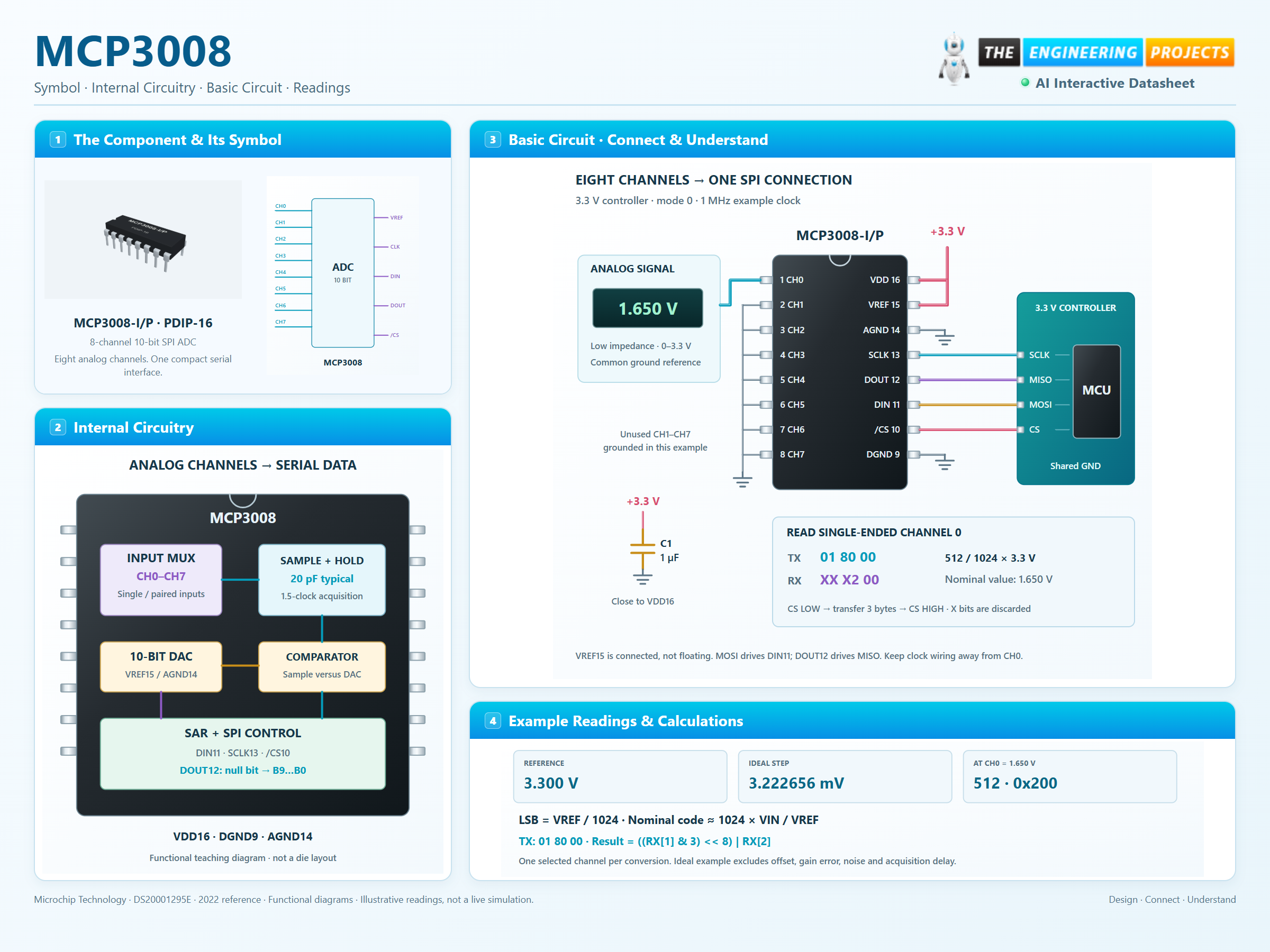
How it works
3 stages · Explore one step at a time
Choose the input
Send a start bit, SGL/DIFF and D2–D0 while chip select is LOW. Single-ended channels use ground; pseudo-differential commands select adjacent pairs.
Acquire and convert
The source charges the internal hold capacitor during the 1.5-clock acquisition window. Ten successive-approximation steps determine the result.
Read the serial word
Sample DOUT on rising clock edges. Discard the null bit, keep the ten result bits and return chip select HIGH before the next conversion.
Choose a channel. Build the SPI message.
Explore 10-bit conversion and single-ended or pseudo-differential inputs.
Channel selection is part of every conversion command. Differential results remain unsigned; a negative difference clips to zero.
01 80 00Three transmit bytes · hexadecimalXX X2 00X = discard · retain 10 result bitsCS pin 10 stays LOW for the transaction. Use SCLK pin 13, mode 0 or 3. Read ((RX[1] & 3) << 8) | RX[2], then raise CS. Ideal code calculator and SPI command builder. It rounds to the nearest nominal code, clamps to 0–1023 and excludes timing, acquisition error and noise. Pseudo-differential IN− is limited to ±100 mV. Read the physical device using its specified SPI timing.