 BETA
12-bit I²C DAC with EEPROM
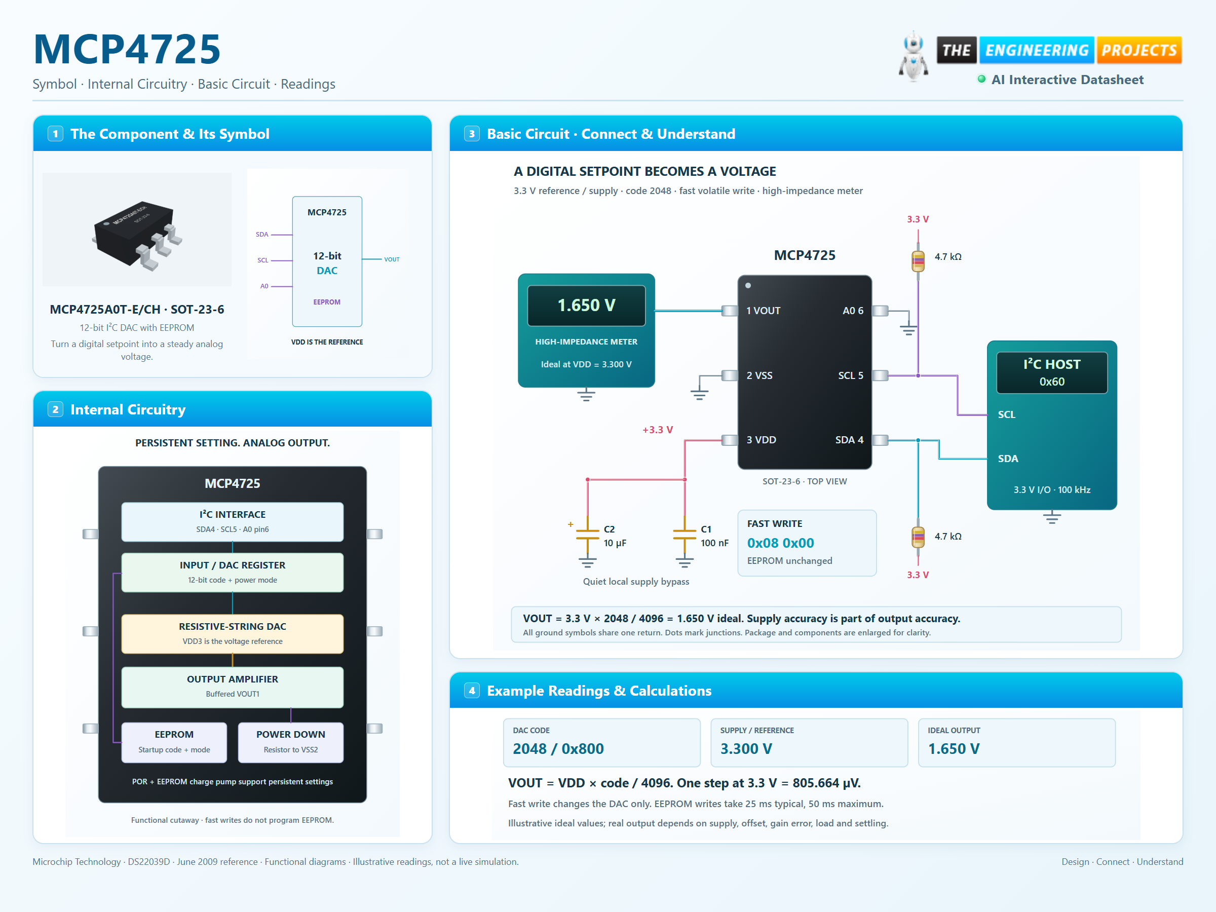
MCP4725 Working Principle
Learn how MCP4725 works with an illustrated explanation and practical readings.
MCP4725 at a glance
Follow the labeled connections and functional stages
How it works
3 stages · Explore one step at a time
Power a clean reference
Use 3.3 V at VDD and a common ground. Local 100 nF and 10 µF bypass capacitors reduce supply disturbance.
Write the midpoint
At seven-bit address 0x60, the fast-write data bytes 0x08 and 0x00 load code 2048 in Normal mode without writing EEPROM.
Measure the output
An ideal 3.3 V × 2048 / 4096 gives 1.650 V at VOUT. A high-impedance meter avoids excessive loading.
Step 1 of 3