 BETA
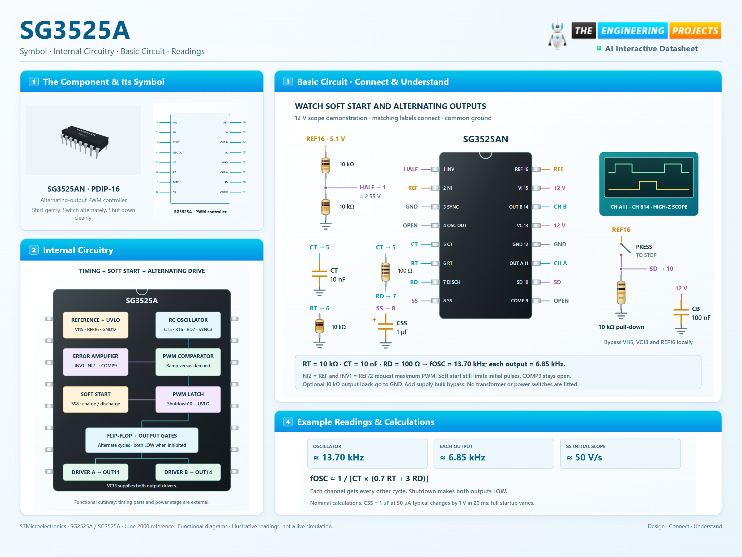
Alternating-output PWM controller
SG3525A Working Principle
Learn how SG3525A works with an illustrated explanation and practical readings.
Package view
SG3525A at a glance
Follow the labeled connections and functional stages
How it works
3 stages · Explore one step at a time
Set the clock and dead time
RT6 and CT5 set the charging interval. RD between pins 5 and 7 lengthens capacitor discharge and the blanking interval.
Release pulses gradually
Soft start limits PWM demand as its capacitor charges. The error amplifier determines the requested conduction after startup.
Steer and protect
Outputs A and B take alternate cycles. Shutdown or undervoltage lockout makes both outputs LOW.
Step 1 of 3