 BETA
Set a nominal 10 kHz clock
Connect 1 nF to CT and 100 kΩ to RT, both returning to ground.
Build a basic TL494 circuit with labeled pins, component values and connection guidance.
A 12 V controller with low-current resistive loads.
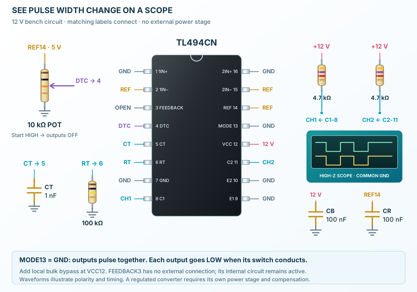
Follow the component values and pin connections
Connect 1 nF to CT and 100 kΩ to RT, both returning to ground.
Turn the REF-powered potentiometer from HIGH toward LOW and observe the growing LOW pulses at C1/C2.
Power down before changing pin 13 from GND to REF. Push-pull mode alternates the channels and halves each output frequency.