 BETA
Dual-output PWM controller
TL494 Working Principle
Learn how TL494 works with an illustrated explanation and practical readings.
Package view
TL494 at a glance
Follow the labeled connections and functional stages
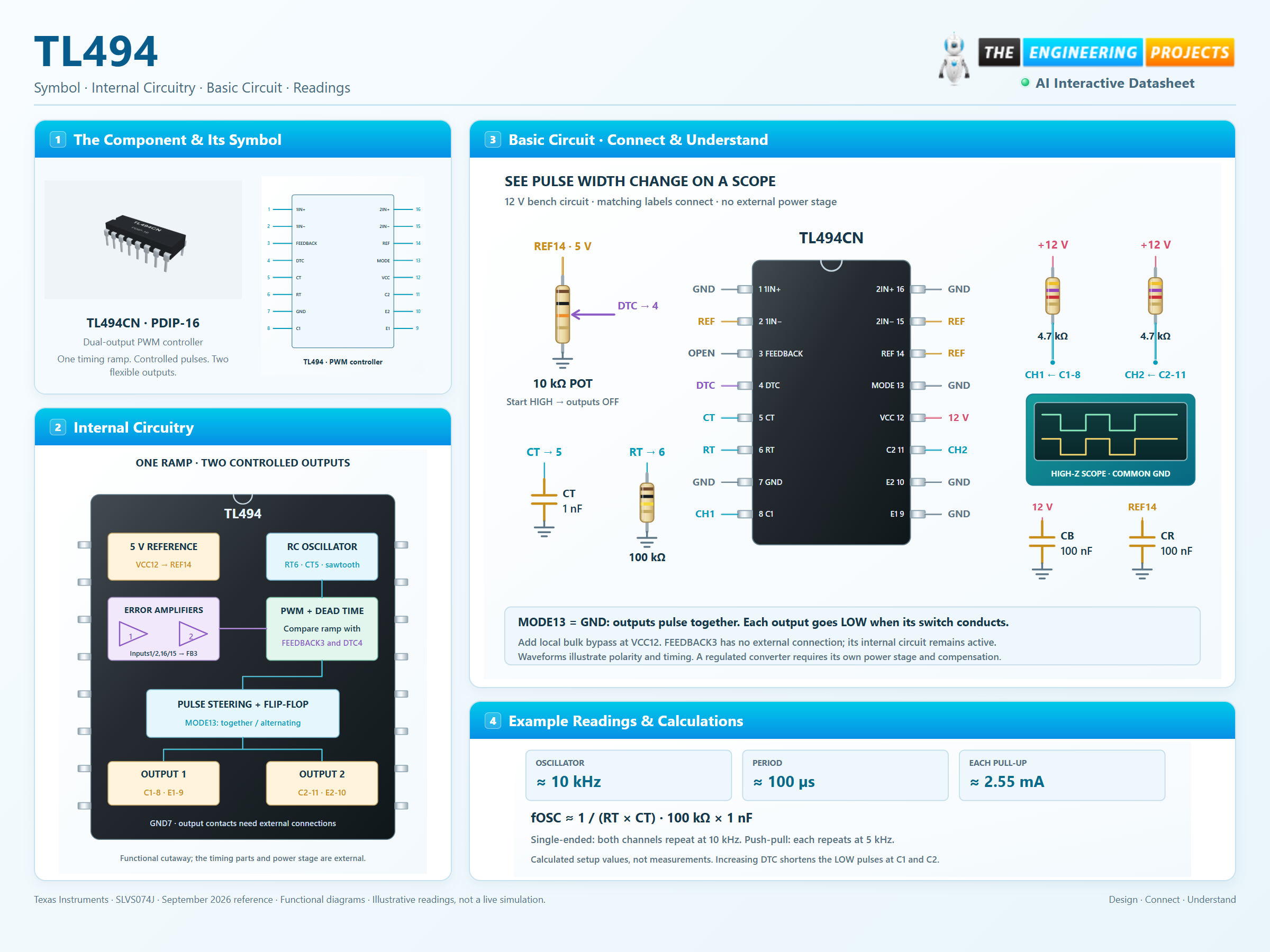
How it works
3 stages · Explore one step at a time
Generate a timing ramp
RT6 and CT5 establish the sawtooth period. The first-order design equation is fOSC ≈ 1/(RT × CT).
Limit pulse duration
The PWM and dead-time comparators suppress conduction when their control voltage exceeds the active timing ramp.
Steer the outputs
Pin 13 chooses simultaneous pulses or alternating channels. Each C/E pair needs a suitable external connection and load.
Step 1 of 3