 BETA
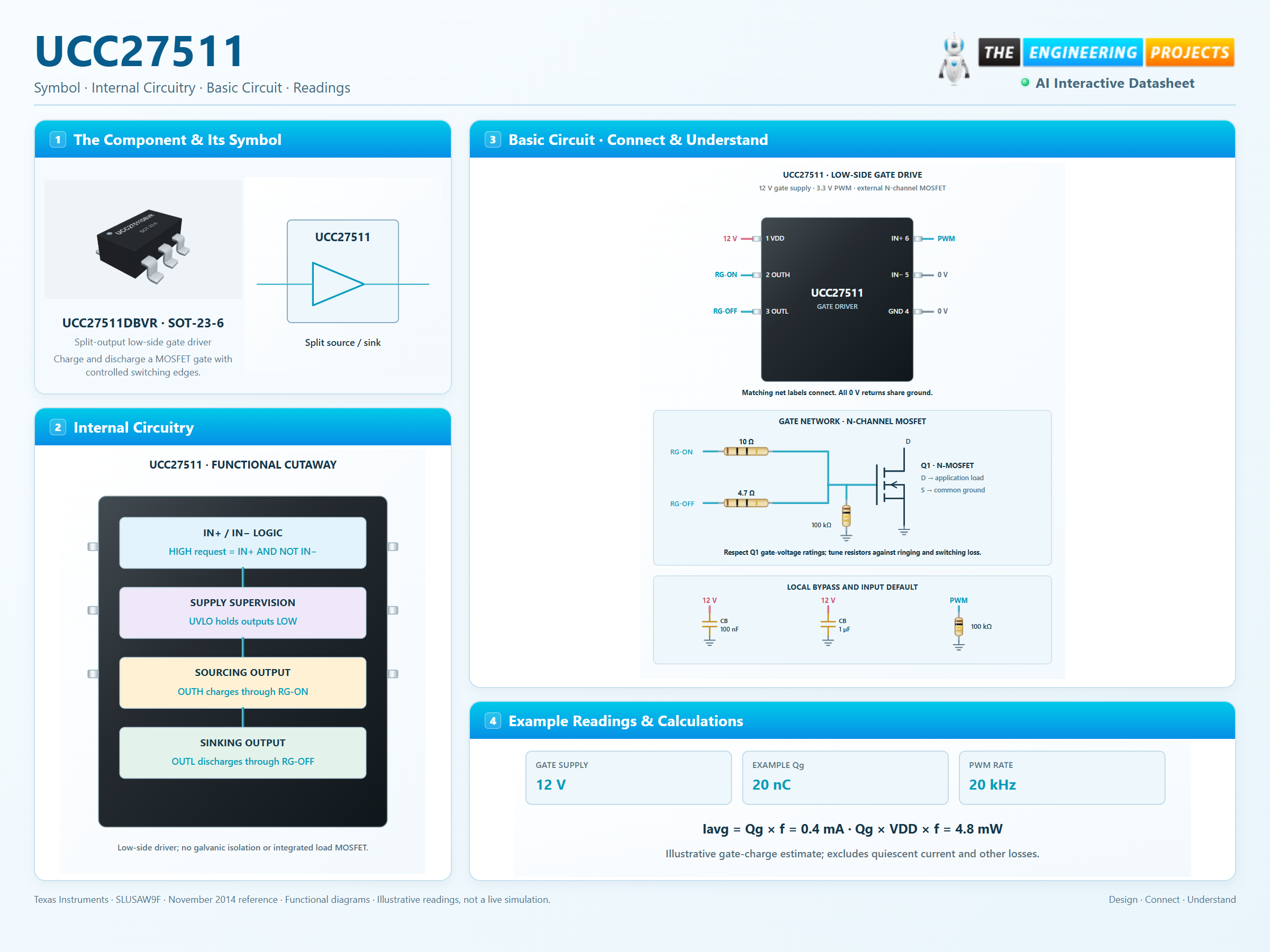
Split-output low-side gate driver
UCC27511 Working Principle
Learn how UCC27511 works with an illustrated explanation and practical readings.
UCC27511 at a glance
Follow the labeled connections and functional stages
How it works
3 stages · Explore one step at a time
Bias the driver
Apply 12 V with short local bypass.
Translate the logic command
IN+ drives the channel while IN− is grounded.
Charge and discharge the gate
The output pulses move gate charge through the chosen resistor network.
Step 1 of 3