 BETA
Connect the load path
Wire the coil between +12 V and 1C pin 16. Connect E pin 8 to the common ground.
Build a basic ULN2003A circuit with labeled pins, component values and connection guidance.
A controller signal switches a 12 V coil through channel 1.
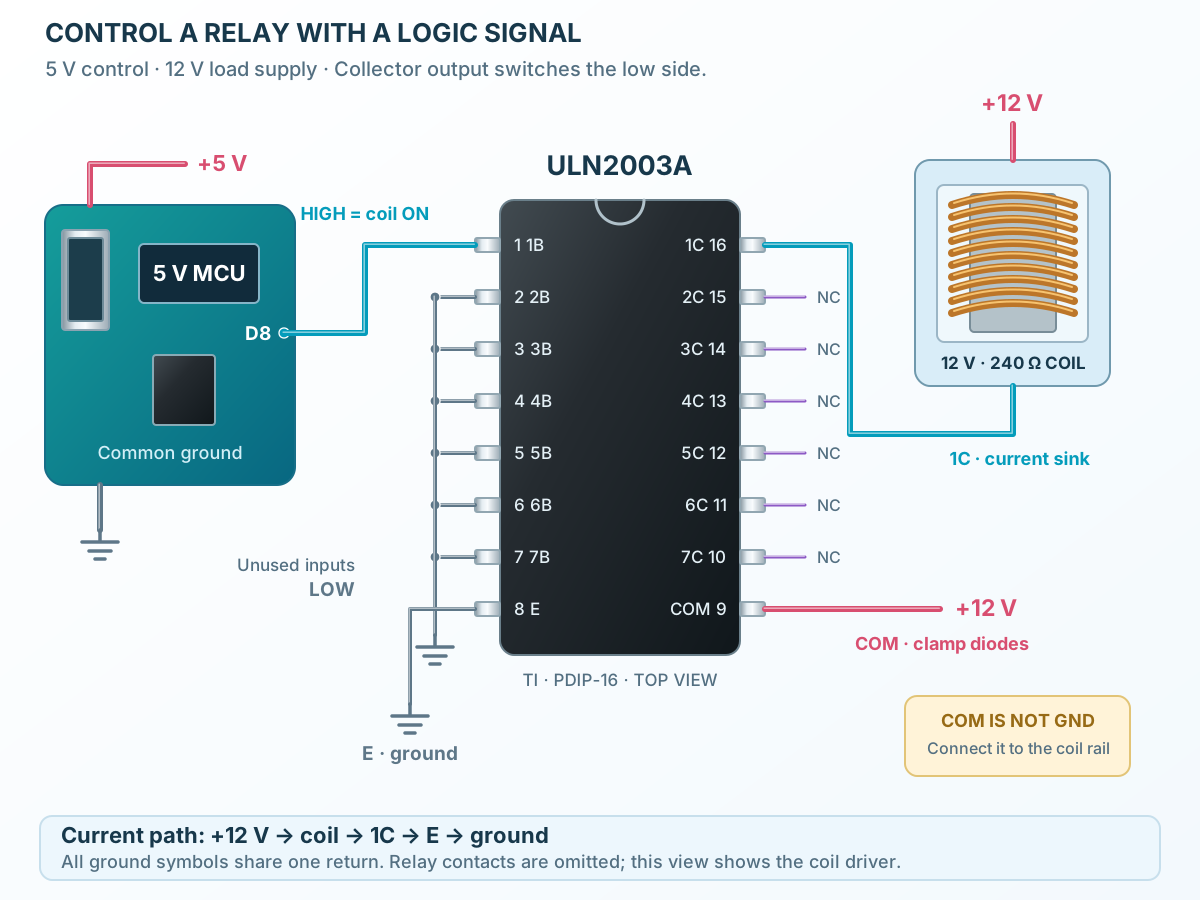
Follow the component values and pin connections
Wire the coil between +12 V and 1C pin 16. Connect E pin 8 to the common ground.
Tie COM pin 9 to the same +12 V rail so the internal diode can carry switch-off current.
A HIGH on 1B pin 1 energizes the coil. LOW releases it. Check pickup voltage with the driver drop included.