 BETA
ULN2003A Working Principle
Learn how ULN2003A works with an illustrated explanation and practical readings.
ULN2003A at a glance
Follow the labeled connections and functional stages
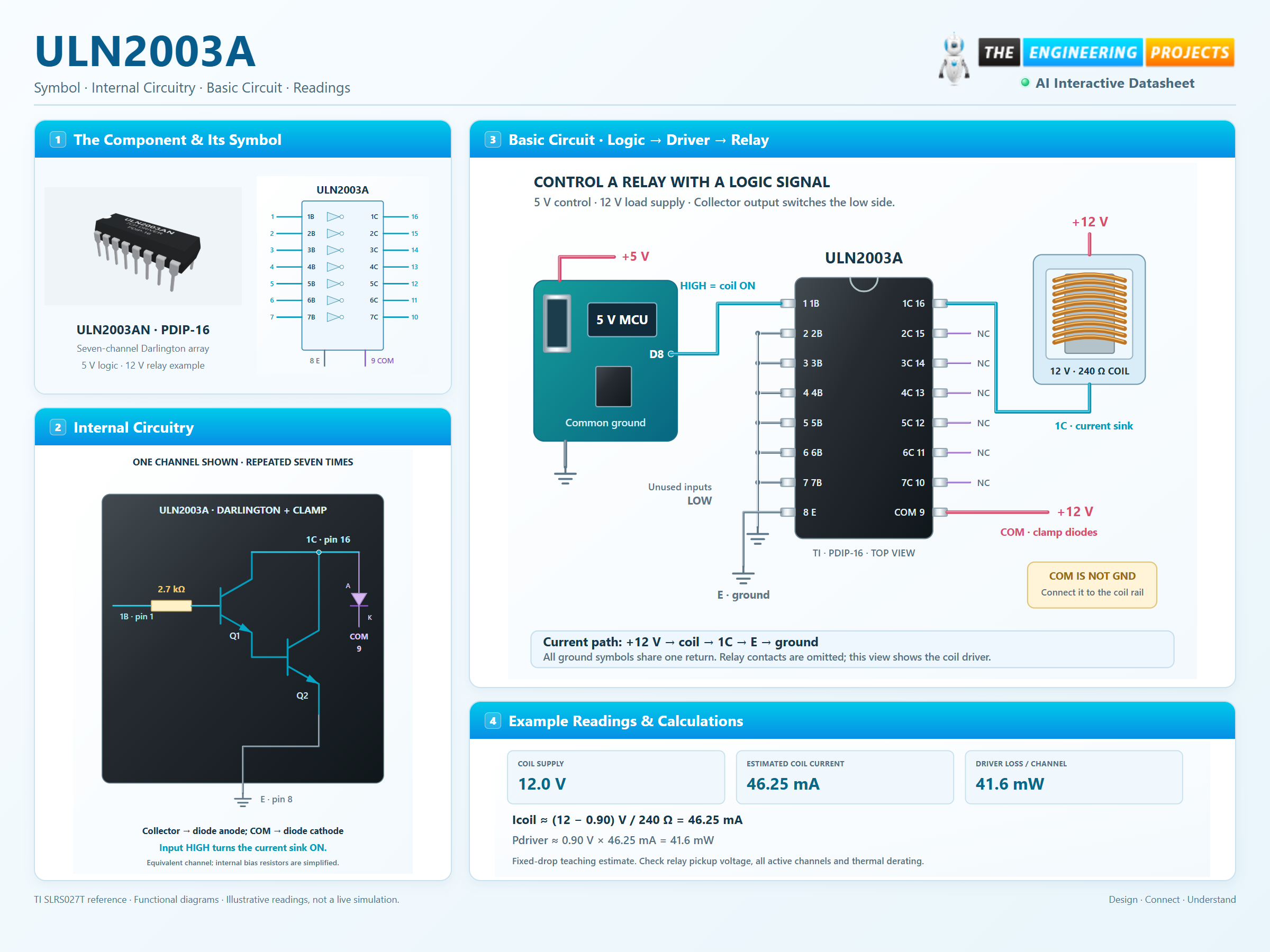
How it works
3 stages · Explore one step at a time
Drive the input
A logic HIGH supplies base current through the internal 2.7 kΩ resistor. Two transistors provide current gain in each channel.
Complete the load current path
The collector sinks current through the load to E. Current flows from the load supply, through the relay coil, through the Darlington pair and back to ground.
Handle switch-off energy
When a coil turns off, its current briefly continues through the internal clamp diode to COM. Connect COM to the coil supply and consider how that supply absorbs the energy.
Switch 7 loads independently
Click an input. Follow its collector current and the combined power budget.
Enable JavaScript to try the drivers.
Illustrative steady-state relay loads. Each coil is 240 Ω on a 12 V supply; the driver drop is fixed at 0.90 V. No relay mechanics, flyback waveform, temperature rise or saturation curve is simulated. COM is connected to the load supply.