 BETA
Current gain
The first NPN transistor drives the second, increasing current gain.
Explore the internal circuitry and functional stages of ULN2003A.
Seven input resistors, seven Darlington pairs and seven clamp diodes.
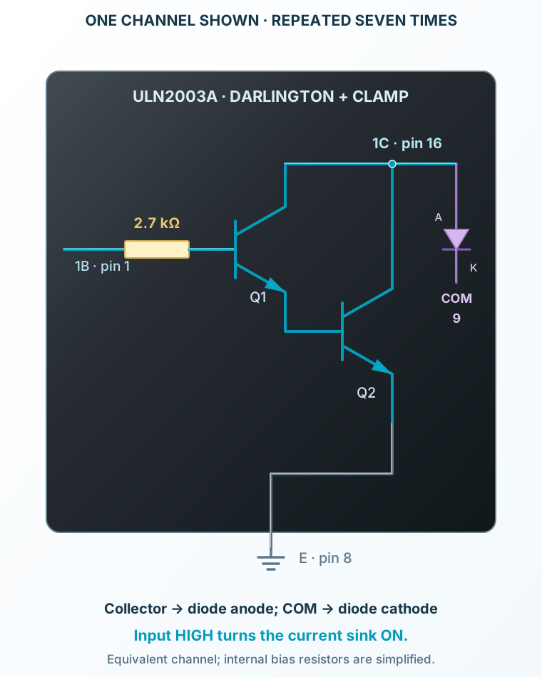
Select a stage to see its role and connections
The first NPN transistor drives the second, increasing current gain.
Both collectors connect to the output. The driver provides a current sink, not a positive voltage source.
The diode anode is at the collector and its cathode is at COM, returning inductive current to the load supply.