Hello friends! In this tutorial, we will design a circuit that connects a 16×2 character LCD to a PIC18F452 microcontroller in Proteus ISIS. We will select the components, wire the display, write a small program in mikroC PRO for PIC, load its HEX file into the simulated microcontroller, and display text on both rows.
This is a useful first microcontroller simulation because it combines several skills in one manageable circuit: choosing the correct device, matching software pins to schematic wires, setting the clock frequency, and checking the result. If you are new to the workspace, start with our Proteus ISIS and ARES guide, then return here for the practical example.
We will preserve the original PORTD connections and two-line website message. The explanation now also covers the LCD control pins, contrast adjustment, compiler settings, and the difference between loading a simulation program and programming a physical PIC.

Understand the Circuit Before Drawing It
The PIC18F452 runs our program and sends commands and character data to the LCD. We use a parallel character display compatible with the HD44780 interface, operating in four-bit mode. Four data wires carry each byte in two transfers, while separate control wires tell the display how to interpret that information.
The display does not understand C source code. Our compiler converts the program into machine instructions for the PIC, and the PIC then uses its output pins to communicate with the LCD. Proteus simulates that interaction when a suitable microcontroller model and its program file are available in your installation.
A 16×2 display provides sixteen visible character positions on each of two rows. That is thirty-two visible positions, but it does not mean every thirty-two-character string can be sent as one line and automatically wrap as expected. We will explicitly write each row from its first column.
Select the Required Components in Proteus
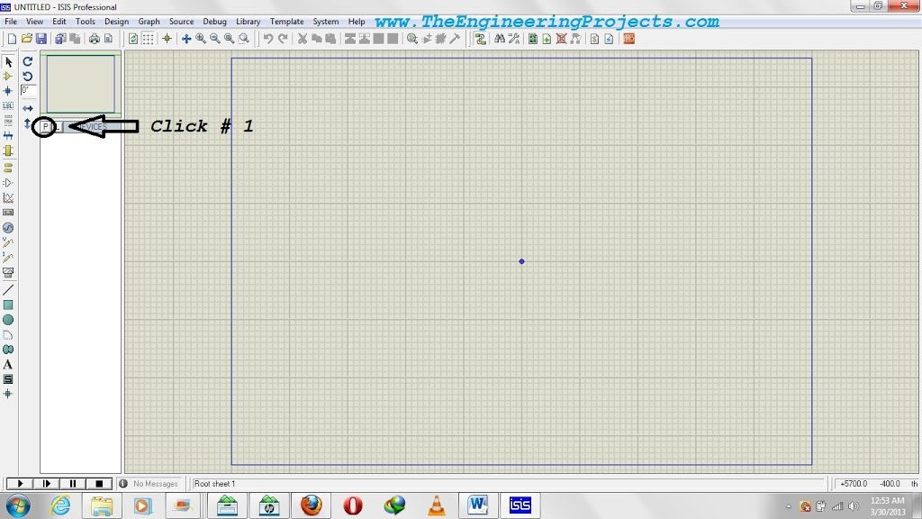
Create a schematic project and open the device picker using the P control shown in the original screenshot. Search for each required part, inspect the available result, and add it to the project's device list. Double-clicking a part makes it available for placement; it does not create a new component in the installed library.
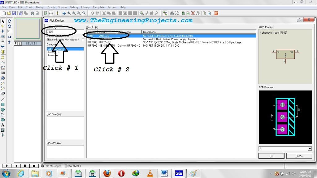
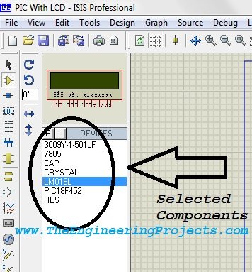
The original component-search example uses a 7805 regulator. Search results can include different packages and model types, so examine the description before choosing. For the LCD, select a supported 16×2 character display model, commonly listed as LM016L in older Proteus libraries. A graphical LCD or an I2C backpack display requires a different interface.
| Component | Purpose | Selection note |
|---|---|---|
| PIC18F452 | Executes the LCD program | Use the same device in Proteus and mikroC |
| 16×2 character LCD | Displays the two text rows | Select a supported parallel LCD simulation model |
| 5 V supply | Powers the logic circuit | Provide a defined supply and common ground |
| 7805 regulator | Produces a regulated rail in the original supply arrangement | Observe the selected part's input and capacitor requirements |
| Contrast potentiometer | Adjusts the LCD contrast voltage | A 10 kΩ potentiometer is a common starting choice |
| Reset pull-up resistor | Keeps MCLR inactive during normal operation | Use a suitable reset arrangement for the physical circuit |
| Clock components | Provide the selected hardware oscillator | Match the clock configuration to a 16 MHz design |
| Decoupling capacitors | Support the supply locally | Include them when transferring the design to hardware |
Place the PIC and LCD with enough space between them to read the signal names. Keep the supply section together and arrange the six interface wires in a clear order. A tidy schematic is useful during debugging because it makes a swapped data line much easier to notice.
Connect the LCD to PORTD
Our original program uses RD2 for RS, RD3 for Enable, and RD4 through RD7 for the four data signals. Keep those assignments identical in the schematic and the program. Changing a wire without changing its corresponding software definition produces a different interface.
| LCD signal | Connection | Function |
|---|---|---|
| VSS | Ground | Supply reference |
| VDD | 5 V rail for this circuit | LCD logic supply |
| V0 or VEE | Contrast potentiometer wiper | Sets character contrast |
| RS | PIC RD2 | Selects instruction or character data |
| R/W | Ground | Selects write operations |
| E | PIC RD3 | Enable signal for transfers |
| D4, D5, D6, D7 | PIC RD4, RD5, RD6, RD7 respectively | Four-bit data interface |
| D0, D1, D2, D3 | Unused in this interface | Not connected to PIC data outputs here |
Connect the potentiometer's outer terminals to the supply rails and its wiper to the contrast input. Begin with a contrast setting that makes the display visible, then adjust it while testing. A blank-looking display can be caused by contrast even when the firmware is running.
The LCD's D4 label is a display data-bit name; RD4 is the PIC port-bit name. They happen to match numerically in this circuit, but that is our chosen mapping, not a universal requirement. RS and E also need their own connections. A display with its data bus connected but its Enable line missing cannot receive complete transfers.
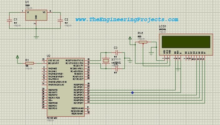
Use the pin names on the selected Proteus symbols and the package pinout in the PIC18FXX2 datasheet. A logical port name is more reliable for explaining the program than copying a package pin number without stating the package.
Power, Reset, and Clock Connections
Make sure the PIC's supply pins reach the correct rails, including any hidden power pins used by the simulation symbol. In physical hardware, connect every required VDD and VSS pin and place local decoupling close to the device. A simulator's simplified power handling should not become an excuse to omit those connections from a real board.
MCLR must remain at its inactive level during normal execution. For hardware, provide the reset network recommended for the selected device and programmer arrangement. If the PIC is held in reset, adjusting LCD contrast or rewriting the text string will not make the program execute.
The original example uses a 16 MHz clock. Configure the compiler project and Proteus processor clock consistently. A physical crystal implementation also needs the correct oscillator configuration and suitable supporting components; entering 16 MHz in a software property does not design that physical oscillator for you.
Create the mikroC Project
- Open mikroC PRO for PIC and create a project in a dedicated folder.
- Select PIC18F452 as the target device.
- Set the project clock to 16 MHz.
- Enable the LCD library in the Library Manager.
- Configure the oscillator and watchdog options for this simple example.
- Add the source below and build the project.
For a basic 16 MHz external-crystal design, select the appropriate HS oscillator setting and disable the watchdog while learning this static example. Review the remaining configuration options rather than assuming a project copied from another PIC has suitable defaults. Device configuration is separate from the C statements that print text.
The mikroC LCD library documentation explains its required signal and direction definitions. The code below uses the original article's PORTD mapping, rather than copying a library example that may use PORTB or a different PIC family.
Code for the PIC18F452 and LCD
// LCD signal connections
sbit LCD_RS at RD2_bit;
sbit LCD_EN at RD3_bit;
sbit LCD_D4 at RD4_bit;
sbit LCD_D5 at RD5_bit;
sbit LCD_D6 at RD6_bit;
sbit LCD_D7 at RD7_bit;

// LCD signal direction registers
sbit LCD_RS_Direction at TRISD2_bit;
sbit LCD_EN_Direction at TRISD3_bit;
sbit LCD_D4_Direction at TRISD4_bit;
sbit LCD_D5_Direction at TRISD5_bit;
sbit LCD_D6_Direction at TRISD6_bit;
sbit LCD_D7_Direction at TRISD7_bit;

char txt1[] = "www.TheEngineeri";
char txt2[] = "ngProjects.com";

void main()
{
    TRISE = 0x07;  // PSPMODE cleared: PORTD is general-purpose I/O
    LATD = 0x00;

    Lcd_Init();
    Lcd_Cmd(_LCD_CLEAR);
    Lcd_Cmd(_LCD_CURSOR_OFF);
    Lcd_Out(1, 1, txt1);
    Lcd_Out(2, 1, txt2);

    while (1) {
        // Keep the static message displayed.
    }
}
The sbit declarations are mikroC syntax. They are not portable C declarations that can be pasted unchanged into every compiler. If you use MPLAB XC8 instead, you need an LCD driver written for that environment and the corresponding register definitions.
How the Display Code Works
The signal definitions tell the library which PIC pins carry RS, Enable, and the four data bits. The direction definitions identify the corresponding TRIS bits. They must be declared before the library calls that use them. If you move RS from RD2 to another pin, update both its signal definition and its direction definition.
The PIC18F452 can use PORTD as a parallel slave port. Clearing PSPMODE keeps it in general-purpose I/O mode for this example. We also initialize the output latch before initializing the display. The LCD library then configures and uses the declared interface pins.
Lcd_Init() prepares the display interface, and the following commands clear the screen and hide the cursor. The two Lcd_Out() calls explicitly write row 1 and row 2 from column 1. The infinite loop leaves the message in place; the display does not need the same text rewritten continuously to keep it visible.
The first string contains sixteen visible characters. The second contains fourteen. In C, each array also includes a terminating null character, so their storage requirements are seventeen and fifteen bytes respectively. The terminator marks the end of the string; it is not an extra visible LCD character.
Load the HEX File into Proteus
After a successful build, locate the generated HEX file in the compiler project's output location. Check that the build completed without errors before assuming the file contains your latest changes. An older HEX file can remain in a folder after an unsuccessful rebuild.
- Stop the Proteus simulation if it is running.
- Double-click the PIC18F452 symbol to open its properties.
- Browse to the generated HEX file in the Program File field.
- Set the processor clock frequency to 16 MHz for this example.
- Apply the properties and start the simulation.
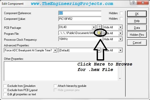
Loading this file tells the simulated PIC which program to execute. It does not program a physical chip connected to your computer. A real PIC requires a compatible programmer and the appropriate programming connections. Keeping those two operations distinct prevents confusion when moving from simulation to a breadboard.
Why the Clock Settings Must Agree
For the PIC18F452, the instruction-cycle frequency is the oscillator frequency divided by four. At a 16 MHz oscillator frequency, that gives 16 MHz / 4 = 4 MHz, with a basic instruction-cycle period of 1 / 4 MHz = 0.25 µs. Some instructions take more than one cycle.
The compiler uses the configured frequency when producing timing-dependent routines. If it assumes 16 MHz while the simulated processor runs at 8 MHz, execution-based delays take approximately twice as long. The same mismatch can affect display timing and later serial examples. Correct the frequency agreement before trying to compensate by randomly changing delay values.
Run the Simulation and Check the Result
The expected result is the original website message split across the two rows. The preserved screenshot below shows the original demonstration. Your initial check is whether both rows appear in the correct order, starting at the first column, without unexpected characters.
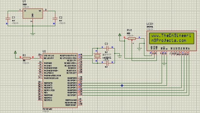
Next, change the strings to two short messages of your own, rebuild the project, and restart the simulation with the updated program. This confirms that you know which source file and HEX file belong to the schematic. If the old message remains, inspect the build result and Program File path before changing the LCD wiring.
When experimenting with shorter replacement messages in a running program, remember that writing fewer characters does not automatically erase characters left at the end of the old text. Clear the row deliberately or write enough trailing spaces. Avoid clearing the entire screen on every rapid update, which can make a real display visibly flicker.
Troubleshoot a Blank or Incorrect LCD
| Observation | Check first | Next check |
|---|---|---|
| Simulation does not start | Simulation log and component model availability | Program file path and supported PIC model |
| Display appears completely blank | Supply and contrast | PIC reset and program execution |
| Blocks appear but no message | Initialization and Enable connection | Clock settings and RS/data mapping |
| Unexpected characters appear | D4 through D7 order | Signal definitions and timing |
| Only one row shows the intended text | Row arguments and display type | Actual string lengths |
| Edits do not change the message | Latest successful compiler build | HEX file selected in Proteus |
Work through one category at a time. A wrong contrast voltage and a wrong HEX path can both produce a disappointing screen, but they require different corrections. Use a short static message until power, clock, initialization, and wiring are understood. Scrolling text adds activity without necessarily making a basic wiring fault easier to find.
Moving from Simulation to Hardware
The simulation is useful for checking the pin map and program behavior, but it does not establish that a physical assembly has adequate power regulation, oscillator layout, or wiring quality. Verify the actual LCD pinout and supply requirements before connecting it. Backlight connections are separate from the logic interface and may need their own current-limiting arrangement.
If a 7805 converts 9 V to 5 V while supplying 100 mA, its approximate voltage-drop dissipation is (9 − 5) × 0.10 = 0.40 W, excluding its own operating current. This example shows why a regulator's temperature depends on both input voltage and load. Use the selected regulator's datasheet to choose capacitors and assess thermal requirements.
Project Review
Before expanding the program, perform three small exercises. First, move the second message to column 2 and check the visible result. Second, replace it with a shorter message and decide how you would erase leftover characters in a program that updates repeatedly. Third, deliberately select an older HEX file, observe that the previous text returns, and then restore the correct file. These exercises connect the editor, compiler output, and simulated device in a way that simply copying a finished schematic does not.
Keep a note of the source folder, target PIC, clock frequency, LCD model, and six signal assignments. If the project is copied to another computer, check the Program File path again. A schematic can retain a path that existed only on the original computer. Package the source and build settings with the design so a future change does not depend on finding one unexplained HEX file.
We have connected a character LCD to the PIC18F452, preserved the original six-signal PORTD interface, and explained the full path from C source to simulated output. The important agreement is between the selected PIC, the compiler configuration, the schematic pin map, and the loaded program file.
Once the static display works, continue with the Proteus component guide or use the LCD in another PIC microcontroller project. Add counters, buttons, or sensor readings one feature at a time so each new behavior can be checked independently.
Frequently Asked Questions
Can I replace the PIC18F452 with a PIC16F877A?
It requires a new device configuration and a review of the registers, pin assignments, and generated program. A HEX file compiled for one PIC is not a general-purpose program for every PIC with a similar package.
Why do we use only four LCD data lines?
The chosen library operates the compatible LCD in four-bit mode. Each byte is transferred in two parts, reducing the number of data connections. RS and Enable are still required, and R/W is held low for writing.
Does the simulation HEX file need to be downloaded separately?
You can generate it from the source in this tutorial using the stated target and clock settings. The old newsletter-delivery promise is not required to complete the project.
Is the LCD backlight proof that the program is running?
No. A powered backlight only demonstrates that its own circuit is receiving power. The PIC can still be in reset, the program can be missing, or the LCD interface can be incorrectly wired.
Why does the program contain an empty infinite loop?
The two rows are written once and remain displayed. The loop keeps the microcontroller in a defined running state without repeatedly clearing and rewriting the same message.