Schottky Diode: Definition, Working & Characteristics
Hello friends, I hope you all are doing great. In our previous lecture, we studied the Basic PN Diode in detail and today, we will discuss a special type of diode called
Schottky Diode. This diode was designed by the German physicist
Walter H. Schottky, so it's named after him, thus called Schottky.
This diode is mostly used in radio frequency (RF) circuits or in power supplies. So let's get started with the basics of Schottky Diode:
Schottky Diode
- Schottky Diode (also called Schottky Barrier Diode or Hot Carrier Diodes), discovered by German physicist Walter H. Schottky, is a special type of diode in which the P-layer(of PN junction) is replaced by the metal layer(i.e. Aluminium, Tungsten, Molybdenum, Platinum, Chromium etc.), while the N layer is of silicon(semiconductor - same as in normal diode).
- As we discussed earlier, the PN Junction of a normal diode is composed of a P-type semiconductor and N-Type semiconductor material, while the Schottky Diode has a metal on one side of the junction and an N-Type semiconductor on the other side.
- You can see in the above figure, we have a Metal Region instead of a P-Type Region, so we can say the junction of the Schottky diode is a doping result of metal and semiconductor(Silicon).
- This Metal-to-Silicon Junction generates a potential barrier of 0.15-0.3V, which is 0.7V for a simple diode.
- In Schottky Diode, the number of electrons is greater than the number of holes and thus electrons are solely responsible for the flow of current, and thus termed as Unipolar, while in a normal diode, both holes & electrons are equally responsible for the current flow and thus termed as Bipolar.
- The Schottky diode symbol is slightly different than that of a
normal diode, as it has a slight bend on both sides of the straight bar.
- Examples of Schottky diodes are BAT49 and 1N5711, manufactured by ST Microelectronics.
Why use Metal-to-Silicon Junction?
The Schottky diode has a Metal-to-Silicon Junction instead of a simple PN Junction, which gives it many advantages over a simple diode.
- The potential barrier of a simple PN diode is 0.7V for silicon, which makes it useless for small signals i.e. radio frequency circuits.
- On the other hand, a metal-to-silicon junction develops a potential barrier of around 0.15-0.3V, making it ideal for low-valued signals.
- The potential barrier of a Schottky diode depends on the metal used and the amount of doping in the N-Type region.
- Because of low voltage consumption, its response rate is high and thus used in fast switching applications.
- If we increase the doping of a semiconductor, it will decrease the width of the depletion region, thus lowering the potential barrier.
Schottky Barrier
- The depletion region created after the doping of metal & semiconductor (as in the Schottky diode) is called Schottky Barrier.
- In simple words, the Schottky barrier is a minimum Potential Energy required for electrons to cross the barrier.
- Once the P.E. of electrons exceeds a certain limit (depending on doping), they overcome the Schottky barrier and start flowing across the Schottky diode.
- The Schottky barrier's width is quite smaller as compared to the depletion region in a normal diode.
- It normally takes 0.15V to 0.3V to overcome the Schottky Barrier, while for normal depletion regions, it takes 0.6V to 0.7V.
- There are further 2 types of Schottky barriers:
- Rectifying Schottky barrier.
- Non-rectifying Schottky barrier.
Schottky Diode Energy Band
- The potential energy level of electrons outside the material is known as the Vacuum level.
- The amount of energy needed to move electrons from the Fermi level to the vacuum level is known as the work function.
- The value of this energy (work function) is different for metals and semiconductors.
- So the electrons in N-type semiconductors have a larger value of P.E than the electrons in metals.
- Let's see the diagram of the energy band of Schottky diode:
Schottky diode Characteristics Curve
- Now, let's discuss the voltage and current characteristics of the Schottky diode.
- It has low forward voltage loss that's why its characteristic curve is close to current axes as compared to normal diodes.
- When the applied voltage to the Schottky diode exceeds 0.15-0.3V, the diode becomes forward-biased.
- Schottky Diode has a Low Reverse Breakdown Voltage as compared to the normal diode and if this limit exceeds, it may damage the component permanently.
Schottky Diode Vs Normal Diode
| Schottky Diode Vs Normal Diode |
| No. |
Schottky Diode |
Normal Diode |
| 1 |
Metal-Semiconductor Junction |
PN Junction |
| 2 |
Low Forward Voltage Loss (0.2V - 0.3V) |
High Forward Voltage Loss (0.6V - 0.7V) |
| 3 |
High Reverse Saturation Current. |
Low Reverse Saturation Current. |
| 4 |
Schottky Barrier created. |
Depletion Region created. |
- In the below figure, you can see the difference between Schottky Diode & normal diode:
Schottky Diode Advantages
- It has a low forward voltage drop.
- It has a fast response time.
- It has a fast recovery time, thus highly efficient.
- It has a high current density and thus can handle high current at low voltages.
Schottky Diode Disadvantages
- It has a high reverse saturation current.
Schottky Diode Applications
There's a long list of Schottky Diode's applications, here I've mentioned a few of them:
- It's used in radio frequency appliances.
- It's used in circuits of Logic Gates.
- It's used in designing rectifiers.
- It's used for controlling reverse current in power supplies.
So, that was all about Schottky Diode, if you still have any questions, please ask in the comments section below. Take care.
Resistors in Parallel Combination
Hello, fellows, I hope you all are doing great. In today’s tutorial, we will discuss the
Resistors in Parallel. There are 2 main connection types that used to make circuitries. One is series contact and second is parallel. If the components in the circuitries are parallel to one another they have their own branch. These branches provide differents path for the current to flow. In parallel circuitries, the current has different value across every segment of circuitry and the voltage across each part is equal to the input voltage. To solve your parallel resistance circuitry you should try our online
Parallel Resistance Calculator
In today's post, we will have a look at such circuitries that have resistances connected in parallel and demonstrates how we can find the equivalent resistance of the circuitry and current and voltage across every component. So let's get started with a
Resistors in Parallel.
Resistors in Parallel Combination
- In electrical circuitries, the resistances are parallel connected if their both endpoints are connected with other resistance or resistances endpoints.
- As in series resistance circuitry, there is one path for the current to flow but in the parallel circuitry, there are many paths for the current. Due to this parallel circuitries are also recognized as current divider circuitry.
- As there are numerous ways for the current in parallel circuitry, so different current will flow across every part of the circuitry. The voltage will be alike to every resistance of circuitry.
- In given below circuitry there are 3 resistances Rx, Ry, Rz, the voltage each of them will be the same.
VRx =VRy =VRz= 12V
- The method to find the equivalent resistance is to just add all series resistance in the circuitry, but in parallel connected resistances we add reciprocal of each resistance for equivalent resistance.
1/Rt = 1/Ra + 1/Rb +1/Rc .....1/Rn
Currents in a Parallel Resistor Circuit
- The net current passing through the parallel resistances circuitry is equivalent to the summation of the currents moving through every resistance of the circuitry.
- But the current across every branch of the circuitry will not be similar, in conclusion, every resistance of the circuitry's branch tell about the current flowing through that branch.
- For instance, as the voltage across every parallel resistor similar and due to different values of the resistance the current will not be alike.
- Let's make a circuitry that has 2 parallel resistances, it is shown in the given figure.
- The current passing through every resistance is IRx and IRy if we apply Kirchoff current law to this circuitry than we have.
It =IRx +IRy
- If we apply ohm law to both resistance than we can find the current passing through them.
IRx = V/Rx= 12/20= 0.6 ampere
IRy =V/Ry= 12/47=0.255 amperes
- So the total current will be.
It= 0.6 + 0.255= 0.855 amperes
Properties of Resistors in Parallel
- In the given diagram a parallel resistance circuitry is shown that has 3 resistances Rx, Ry, Rz in parallel and one current source.
- The current Ix is flowing from the source to 3 resistances of the circuitry and will divide into three different paths.
- If we apply ohm's law to this circuitry than we have this expression.
Ix = IRx? + IRy? + IRz
- The voltage across every resistance will be.
VRx = (IRx) . (Rx)
VRy = (IRy) . (Ry)
VRz = (IRz) . (Rz)
- Now use these voltage value of every resistances and find the current flowing them.
IRx = VRx/Rx
IRy = VRy/Ry
IRz = VRz/Rz
- If we add these 3 current the resultant value will be equal to the current source.
Ohm‘s Law and Parallel Resistors
- To relate ohm's law and parallel combination of the resistor we take an example of the circuitry that the 3 resistors connected in parallel and voltage source are connected with them.
- The voltage across every resistance is equal to the voltage source. If we apply ohm's law the current across every resistance will be.
I1 =(V)/(Rx)
I2=(V)/(Ry)
I3= (V)/(Rz)
- According to charge conservation principle, the total current flowing in the circuitry will be equal to the current passing through these three resistances.
It = (I1 + I2 +I3)
- If we put the values of currents flowing in the 3 resistance then we have.
I = (V)/(Rx) + (V)/(Ry) + (V)/(Rz)
I =V (1/Rx + 1/Ry + 1/Rz)
- From this relation, we can conclude that the total resistance in parallel circuitry is equivalent to the summation of the inverse of every resistor.
- So, equivalent resistance in parallel circuitry is.
Rn = 1/Rx + 1/Ry + 1/Rz +.........+1/Rn
Applications of the Parallel Resistance Circuit
- These are some applications of the parallel resistance circuits.
- Almost every house on this earth uses a parallel combination for electric wiring, as we can on-off and appliances of our home without removing all devices from the circuitry.
- In case of any short circuit occurs at one device or it damage due to some electrical faults, we will off circuit to that particular device not the complete circuitry for fault removal.
- Parallel circuitries are not used only in a home is also used in transmission and distribution of the power to large buildings and different areas.
- Nowadays our grid stations are designed according to parallel circuitries combinations when the circuit of the feeder is trip, other feeders in the grid continue their working and deliver power to the load.
Parallel Resistance Calculator
- As we discussed our Parallel Resistance Calculator now we discuss how you can use it for solving your circuitries.
- You can see in the given figure parallel resistance calculator, there are 2 portions of this calculators first is on the left side where you can add values of your circuits resistances and on right side physical representation of circuitry is shown.
- You can see in the given diagram, I have put different five values in the value box and get equivalent resistance of the circuitry. If your circuitry has large no of resistances you can add more resistance values by Add More Resistance option. You can also take values in kilo-ohm and mega-ohm.
It is the detailed article on the Resistors in Parallel if you have any question ask in comments. Thanks for reading.
How to Transform a Non-Profit Business with EOS
Hello friends, I hope you all are doing great. In today’s tutorial, we will discuss
How to Transform a Non-Profit Business with EOS. EOS has been gaining popularity around the world, enhancing the level of the business. With experienced EOS implementers, any company can achieve the heights that they have thought. However, the question arises “Can EOS implementers help these non-profit organizations as well”? How come these EOS implementers help small budgeted companies with no profit? How their tactics play an important role in right traction?
There are many organizations that provide consultancy to help companies and their leaders to manage their work in an easy systematic way. If you are looking for a
business growth consultant, you can avail it from Traction for Businesses. So, let's get started with
How to Transform a Non-Profit Business with EOS.
How to Transform a Non-Profit Business with EOS
What is EOS?
- If we continue with EOS implementers, one should know what EOS is? It is a comprehensive business management system that works on a set of proven tools to help business leaders to get expected results and helps in achieving Vision, Traction, and Healthy.
- This system helps in learning the methods that ensure accountability in any business.
- Though, EOS is the fastest growing platform that allows running many applications over the network.
- EOS was developed with for-profit companies in mind, and the same principles apply to non-profit organizations as well that are fighting in the market to be innovative and entrepreneurial.
- If your leadership team is honest, and willing to be vulnerable with each other, then you’re the right kind of organization to run on EOS.
- Any organization that entirely relies on the people to do its work can get benefit from the Entrepreneurial Operating System (EOS).
Why is EOS Implementers needed?
- EOS is based on simple concepts, which is one of the reasons it’s proven to be so powerfully effective.
- The real question is, Do we need EOS implementer? Can business leadership self-implement EOS?
- People have enough potential to implement it on their own, but should they?
- There can be many challenges in self-implementing EOS that’s why we need Certified EOS implementers who can provide a vision and discipline to your company.
- These implementers are experienced in their disciple and can be reliable traction for companies with low profit.
How EOS helps the company to get on track?
- It is common sense to know your targets before the year starts and to keep track of your goals is necessary to achieve success.
- However, the problem arises when a company has no idea of their progress and whether you are on the right track in achieving the expected success.
- However, EOS tools have made this thing more comfortable to keep your tracks under your control.
- It requires an EOS expert who can help you out in setting milestones and getting along with it.
- It needs a strategy and needs to move step by step accordingly. With the help of EOS tools, you will see a noticeable improvement in keeping track of your targets.
- So why wait till it’s late, hire an EOS implementer and move your company with expected profit and success.
So, it is the detailed article on How to Transform a Non-Profit Business with EOS, if you have any question ask in comments. Thanks for reading. Take care until the next tutorial.
5 Reasons to Get A Degree in The Engineering Field
Hello, fellows, I hope you all are doing great. In today’s tutorial, we will discuss
5 Reasons to Get A Degree in The Engineering Field. Engineering represents the practical application of science and mathematics to find solutions to technical problems. Engineers don’t just sit back and watch. On the contrary, they design, invent, fix, improve, research, and so on. Engineers bring things to life, whether it’s physical buildings or robots.
If you want to create technology and products that make our lives easier, think about getting a degree in the engineering field. Not only is it one of the most popular college majors but also one of the most profitable ones. It might just be the right fit. These reasons will convince you that engineering is the best degree. So let's get started with
5 Reasons to Get A Degree in The Engineering Field.
5 Reasons to Get A Degree in The Engineering Field
Prestige, Acceptance, And Power
- Stop for a moment to think about the value of college education. If you earn a B.A, in general engineering from no matter what university, you can do everything you want.
- Well, almost. You can work in a laboratory or take on hours in a non-engineering industry like finance.
- The point is that you won’t regret the money or years spent to get the degree. People will be amazed when they find out that you’re an engineer.
- Your status will automatically win you the respect and trust of your acquaintances.
- Needless to say, engineers enjoy the same prestige as lawyers and healthcare professionals.
- Some of the most prestigious institutions in higher education offer engineering degrees. Examples include but aren’t limited to:
-
- Georgia Institute of Technology
- Indian Institute of Technology Delhi
- Nanyang Technological University
- The University of Cambridge
- Harvard University
- ETH Zurich
- Just imagine what it would be like to graduate from a top educational institution.
- The engineering schools mentioned earlier offer the most competent, innovative, and effective graduates, so it’s not hard to find employment.
- What is more, the element of respect comes naturally.
You Can Make A Difference in The World Around You
- Any person can make a difference in the world, let alone an engineer. Being part of a project, small or big, enables you to contribute to society.
- You have the opportunity to create technological advancements that improve the way people live.
- Take medical equipment as an example. You can work alongside doctors, therapists, and researchers to come up with innovative medical solutions that can solve clinical problems.
- MRI machines, hearing implants, and ultrasound equipment wouldn’t have been possible if it weren’t for engineers.
- In engineering school, you’re encouraged to reach meaningful goals and focus on the impact of globalization.
- The knowledge and skills that you acquire during your student years will enable you to work in various international settings, as well as work environments.
- You can use technologies to the same extent as your peers in other parts of the world.
- The world is becoming increasingly connected, so it’s necessary to think globally.
- You’ve got the power to shape the way individuals travel, communicate, exercise, and how they make use of energy.
- At the end of the day, you’ll feel that you’ve really made a difference, which is no little thing.
High Standards Let You Know What You Aim For
- Contrary to popular opinion, university standards haven’t fallen. Students enrol into programs that promote academic rigour and which are delivered by high-class educational institutions.
- Engineering schools, in particular, establish very high standards. The result is that students have a good idea of what to aim for.
- The vast majority of students learn more than is required of them. They hire private teachers so that they know everything about building machines and products.
- You too may need assistance on certain subjects. Tutors have a student-centred approach, so everyone makes progress.
- Your tutor may be a current or former school teacher or perhaps someone with experience in the field.
- You’ll be able to strengthen subject comprehension and build significant learning skills. In order to become an engineer, you need excellent grades. Most courses don’t accept anything other than the best.
- Yes, you’ll have to work hard, but you’ll be among the best. When you pursue general engineering, you have the chance to broaden your mind, increase your skillset, not to mention specialize in your area of interest.
- You’ll receive your degree from industry professionals who know a thing or two. Understand the qualifications needed for the college or university you’re thinking of applying to and get ready.
You Can Travel Around the World
- So, you have a big desire to travel the world. If you want to explore the world while earning money and building your career, you should definitely study general engineering.
- There are many, many opportunities for travelling and discovering new environments.
- Cruise ships, for example, need engineers. If you haven’t started a family, you can obtain a high-paying job that enables you to travel without spending money on accommodation.
- Let’s take another example. You can become an oil and gas field professional. There’s no shortage of travel opportunities.
- As an engineer, you enjoy a great deal of freedom. You can go into technical consulting and you’ll be constantly on the move.
- After a while, you’ll get tired of covering the ground. Or maybe you won’t. Even if you don’t want to travel the world, you’ll have to in order to make your career progress.
- You’ll get to experience life in a completely different culture, become fluent in a foreign language, and work with international clients. Don’t miss out on such an opportunity.
Ready for Any Problem With 10 Solutions
- Some life challenges are exceptionally difficult to handle. With a degree in engineering, you’ll be able to handle most issues.
- In school, you’re introduced to all kinds of situations that need to be solved using engineering skills.
- You even learn how to organize a messy desk. Chances are that you’ll encounter bigger problems that you did during your years of school. Nevertheless, your confidence and skills will help you in the decision-making process.
- You’ll have at least 10 solutions for every problem.
- Engineers are capable of solving all kinds of problems. Do you know what tool they resort to the most? Their creativity.
- Start approaching each situation as an opportunity to learn. If you can’t come up with a solution yourself, seek guidance from others.
- Nothing is unsurmountable. There’s no better degree that can teach you problem-solving skills than engineering.
- The choice is up to you. To be more precise, decide if going to engineering schools is or isn’t the right thing for you.
It is the detailed article on the 5 Reasons to Get A Degree in The Engineering Field if you have any question ask in comments. Thanks for reading.
How Virtual Reality Helps Field Engineers Deliver Value
Hello, fellows, I hope you all are doing great. In today’s tutorial, we will discuss
How Virtual Reality Helps Field Engineers Deliver Value. It’s no secret that technology is advancing rapidly and is transforming how field engineers are accomplishing tasks in projects. With virtual reality taking the lead, we are witnessing an unprecedented improvement in project quality and design in the engineering field.
Virtual reality engineering involves visualization of projects using 3D modelling tools. It introduces the users directly into a computer-generated virtual environment, giving them an idea of what to expect in the field. With this technology, a field engineer can identify the potential risks and flaws in a project before implementation. So let's get started with
How Virtual Reality Helps Field Engineers Deliver Value.
How Virtual Reality (VR) Works
- Virtual reality is a trending technology that’s prominent in the gaming industry. But due to its potential, VR has proven to be a valuable asset in training.
- Today, almost every industry is adopting virtual reality in its processes, including the construction sector.
Virtual Reality in Real Estate
- When it comes to marketing in real estate, virtual reality has become an indispensable tool in the industry. This technology allows home sellers to showcase their properties through an interactive interface.
- With virtual reality, homebuyers can assess the interior features of a house they intend to buy, making the process faster and cost-effective.
Virtual Reality in Construction
- While some people perceive virtual reality as a gaming technology, it is also helpful in the construction industry.
- Construction engineers can use the technology to design buildings, train workers, and promote on-site safety standards.
- In the project design phase, engineers can showcase the building plans to their clients and customers.
- The project designers use VR headsets to visualize the simulated virtual world of a construction project.
How to Use VR Headset in Construction
- The headsets are usually linked to a smartphone or computer to transmit data. If you are using a smartphone, you can download the app for virtual reality.
- The VR app integrates well with the VR headsets, allowing engineers to visualize images in three dimensions.
Virtual reality headsets, also known as head-mounted devices (HMD), may come with additional accessories to help engineers navigate the virtual world.
- Such features include wireless controllers and sensors.
Applications of Virtual Reality in the Engineering Field
- Virtual reality offers an immersive experience to field engineers, allowing them to interact with projects virtually before implementation. Here is how VR technology has transformed operations in engineering.
Training of Field Engineers
- Virtual reality training allows engineering companies to expose employees to new working environments without harming them virtually.
- Also, VR training reduces the maintenance costs of equipment that workers might have damaged during the actual training.
- For instance, construction companies have incorporated VR training in their operations to promote the safety of workers.
- With virtual reality, workers can get exposed to great heights, confined spaces, and heavy equipment like excavators and cranes.
- In some cases, the death of workers usually results from physical training exercises. For that reason, construction engineers see virtual reality as a potential tool for reducing fatalities.
- Virtually trained workers can handle and operate physical machinery with much care.
- As an OSHA-approved technology, virtual reality is a valuable tool for promoting the safety of workers in the field. Read this blog post by Procore Technologies to get more info about OSHA safety tips and standards.
Design and Development
- As an integral part of engineering, designing helps engineers to gain insight into a project before implementing it practically.
- Most designers have invested heavily in virtual reality to help them curb complications that might arise during project implementation.
- With the help of virtual reality, construction engineers and architects can virtually get an accurate and detailed representation of a building before laying any foundation.
- When used together with 3D modelling and BIM, designers can easily tour workspaces.
- Besides modelling buildings, virtual reality has also been a ubiquitous technology in car design. Car manufacturers use this technology for prototyping when designing vehicles.
- It eliminates the need to develop physical prototypes, saving on design costs.
- Virtual reality can also be useful in pinpointing mistakes in project design. Once the field engineers have identified the potentially hazardous risks, they can record them in a punch list to correct them later.
- Designing a project can involve many people and needs a collaborative platform to accommodate all stakeholders.
- Virtual reality can allow various people with different expertise to interact in real-time on a single platform.
- With a well-established collaborative framework, designers and engineers can know every progress in an engineering project.
- That can help designers to make informed decisions, reducing complications that might arise during project implementation.
Virtual Reality Prototyping
- In the past, field engineers used to develop products from a conceptual view. They would use quantitative measures from statistical data to define product features.
- That made the production more expensive, risky, and time-consuming.
- In recent times, virtual reality prototyping has become an integral part of any design process. Engineers are using the technology to create, test, and validate projects before implementation.
- Virtual reality prototyping reduces the time it takes to complete a project, saving costs.
- With VR prototyping, designers don’t have to manufacture expensive prototypes for trial projects. Most companies have adopted VR prototyping in product testing to save on time and money.
- Such companies include Peugeot, BMW, Boeing, Jaguar, Ford, and Airbus.
Final Words
- It's apparent that virtual reality is already making a significant impact on the engineering field. Field engineers are using this valuable tool to leverage complex production processes to improve project quality and productivity.
- Virtual reality provides access to simulations that would help every stakeholder to visualize and understand projects.
- By adopting VR technology in engineering, companies can make their designs and operations more interactive.
- Since virtual reality is a potentially profitable technology, we expect more companies to adopt it. There is no doubt that VR technology is the future of engineering.
- According to Architosh, it's estimated that the engineering industry will have devoted $4.7 billion to virtual reality by 2025.
It is the detailed article on the How Virtual Reality Helps Field Engineers Deliver Value if you have any question ask in comments. Thanks for reading.
Resistors in Series Combination
Hello, fellows, I hope you all are doing great. In today’s tutorial, we will discuss the
Resistors in Series Combination. In electrical and electronic engineering there are 2 main methods by which components are connected. First one is series and second is parallel. If the components are connected in series then the similar current will flow all of them but the voltage across them will be different. The sum of the voltage loss across every component will be equal to the total applied voltage.
While in case of the parallel connection the voltage across every component will be the same and the current will follow different in every component. In today's post, we will discuss such circuits that consist of the resistance in series combination and find the value of current and voltage across every resistance. If you want to solve your series resistances combination, you should use our online
Series Resistance Calculator. So let's get started with the
Resistors in Series.
Resistors in Series Combination
- The circuitry that has a connection of the resistances in a single line is called a series resistance circuit.
- In this method of the resistance connections, the value of current remains the same across every resistance.
- You can see in the given diagram, the current across each resistance will be the same.
IR1= IR2 =IR3 = 1mA
- In this given circuitry there are 3 resistances are connected in series, that is R1, R2, R3.
- As the circuitry has a series combination of the resistance so, to get total resistance of the circuitry we will add all these 3 resistances.
Rt = R1 +R2 +R3
- If we put values of these resistances in the above-given equation we will get the equivalent resistance of the circuitry.
Req = 2O + 3O + 5O =10O
- So the equivalent resistance of the circuitry will be ten ohms, it can also be defined as the resistor that can be added in place of all resistances in circuitry is known as the equivalent resistance of the circuitry.
- The final expression to find the net resistance of the circuitry is given as.
Rt = Rx + Ry + Rz + ….. Rn
The voltage of the Series Resistors
- In above-given circuitry, we can see that the value of the voltage across every resistance is different from others. It is because the voltage drop across each resistor is different due to the difference value of the resistances.
- We can find the total voltage at the terminals A and of the circuitry by the given formula.
Vt = VR1 + VR2 + VR3 = 10V
- If we apply Ohm's Law to every resistance we can find the value of the voltage across each resistance.
VR1= I x R1= 1A x 2O = 2V
VR2 =I x R2 = 1A x 3O = 3V
VR3= I x R3 = 1A x 5O = 5V
- If we add thses voltage we get the ten volts that are equals to the applied voltage to the circuitry.
- So, we can conclude that the total voltage of the series circuitry is equal to the sum of the voltages across every circuitry.
Vt= VRx + VRy +VRz+........+ VRn
The Voltage Divider Circuit
- In the given diagram, you can see the circuitry that has 2 resistance Rx and Ry, connected in a series.
- The input voltage is provided at the resistance Rx and the output is taken from the resistance Ry.
- The value of the output voltage can be found by the voltage divider formula that is given below.
Vout = Vin (Ry)/(Rx+Ry)
- Now solve such circuitry that has the more than 2 resistances, in given circuitry you can see there is 4 resistor and their values are also mentioned.
- We now apply the voltage divider formula to find the value of voltage across every resistance.
Vab = VR3= Vs x (R3/R1+R2 +R3+R4)
= 10 x (30)/ (10+20+30+40)
Vab = 3V
Applications of Resistors in Series
- To see the practical application of the series resistaces we construct an circuitry and solve it.
- You can see the circuitry in the figure that is similar to the circuitry that we discussed in the voltage divider circuit, but in this circuity, there is a light-dependent resistance, it will convert any physical quantity into the electrical signal.
- Let's suppose that the value of the LDR is ten-kilo ohm and resistor RX value is a thousand ohms if we apply the voltage divider rule than we have.
Vout = Rx/(Rx +Ry) x Vin
=1000/(10000 +1000) x 12
Vout =1.09
Series Resistance Calculator
- As we discussed earlier our online Series Resistance Calculator now we explain how it works practically.
- In the given figure, you can see the practical representation of the calculator.
- There are two portions of this calculator first is value box where you put values of your circuitry resistance these value can be in ohm, kilo-ohm, mega-ohm, according to your requirements.
- In other portion, there is circuitry that will show the practical implementation of your circuitries.
- In given figure I added four different values of the resistances in the value box, you can add any no of resistances by Add More Resistance Button, and the equivalent resistance of the 4 resistance is shown in Req box.
- The circuitry of the four resistances is shown on the right side in the figure.
It is the detailed article on the resistors in series if you have any question ask in comments. Take care until the next tutorial.
Three Types of Banners to Maximize Brand Awareness
Hello, fellows, I hope you all are doing great. In today’s tutorial, we will discuss
Three Types of Banners to Maximize Brand Awareness. The goal of all forms of advertising is one simple thing - to “wow” your prospective customers and other business associates. Banners help you achieve this oomph factor, provided you make the right choice of format, design and printing.
Selecting the most appropriate format and creating visually appealing designs don’t need to cost a bomb, say experts at Print Banners, a company that provides high-quality design and
same day banner printing in NYC. What’s important is to make informed decisions. So, let's get started with
Three Types of Banners to Maximize Brand Awareness.
Three Types of Banners to Maximize Brand Awareness
Horizontal Banner Stands
- Often, horizontal banner stands allow companies to better customize the appearance, layout and impact of their advertising campaigns.
- Whether you choose vertical and horizontal banner stands, it’s imperative to focus on an attractive design, with a vibrant display of compelling graphics and text.
- The space in question, where the advertisement will be displayed, should make the choice between these two formats.
- Horizontal banner stands are often better suited than vertical ones for displaying your brand and offering along the aisles in supermarkets, at large events like mega tradeshows and sporting events or placed at the top of a store or restaurant.
- If there’s a large wall to be covered or you wish to grab attention and make an impression right at the entrance, it’s best to choose horizontal banner stands.
- This format supports longer running text and gives enough room for providing contact details.
- The most common materials used in this format are closely knitted fabric, PVC mesh and vinyl.
- With high-quality printing, they’re best for visually powerful messaging.
Retractable Banner Stands
- Retractable banner stands are particularly popular in New York. This is because NYC is known for its hectic events calendar.
- With several events hosted every week, people in NEW YORK choose retractable banner stands for their portability.
- They are easy to transport and simple to assemble and adjust to the space allocated.
- Your booth at a New York tradeshow may not be very large. When space is limited, retractable banner stands are the best choice, as they take up minimal floor space.
- This leaves your team more room to walk around and interact with guests.
- Also, these are very versatile and can be used for a variety of events, ranging from corporate parties to mega tradeshows.
- They can also be used to build brand awareness, make announcements or provide directions.
Backdrop Banner Stands
- With the events scene in NYC being so hectic and many competitors participating, backdrop banner stands to help your brand to stand out of the crowd.
- These may have a single layout or a step and repeat design and there are several material options for you to choose from.
- Backdrop banners stands are perfect for tradeshows and other indoor events in NYC.
- They provide a branded and vibrant background for your event photographs, ensuring that you get mileage from the investment long after the event is over.
- These photographs, with your brand displayed in the background, can be sent to newspapers and magazines as well as shared on social media to continue the branding activities.
It is the detailed article on the Three Types of Banners to Maximize Brand Awareness if you have any question, ask in comments. Take care until the next tutorial.
Best Search Engines Going Forward
Hello, fellows, I hope you all are doing great. In today’s tutorial, we will discuss the
Best Search Engines Going Forward. The dominant search engine on the web for the first fifth of the 21st century had a nice run, but it can't last forever. While this has been happening, a new generation of web users has become aware that Internet trends have stagnated. After all these years of websites carefully toeing the line to avoid offending the dominant search engine, the web has become homogenized.
There are new vistas in web search engines out there. The way we do it now is by far not the only way, and search engine technology is most definitely not a closed field. At the same time, the next-generation web market is starting to take exception to be spied on, having their data sold to third parties, and being tracked everywhere by a world-spanning mega-corporation. The future of search might just lie with other search engines out there. So, let's get started with
Best Search Engines Going Forward.
DuckDuckGo
- DuckDuckGo is simple to explain: they're a search aggregator which skims results from other search engines and molds it to its own purpose.
- The difference is that it serves up these results without tracking the user or recording the users' data.
- Not only does respecting the users' privacy avoid having their personal browsing data compromised by third parties, but getting out of the filter bubble of personalized search results means you see a complete picture of the web, not just the part that a corporation wants you to see.
Yandex
- Not many in the western hemisphere are familiar with Yandex, and yet it's been in business since 1997.
- One of the top ten biggest search engines, https://yandex.com/ is unfiltered and fast, serving up results that seem to be mysteriously missing from other mainstream search engines.
- Like any developed web technology company, they offer a side of features and services, along with far fewer ads.
Hot.com
- https://hot.com is an example of a niche search engine. It finds adult results only.
- No matter what you search for, it only crawls those websites, social networks, dating sites, and so on.
- It does this without tracking your data or keeping you in a filter bubble either. While its subject matter is certainly a commonly-expressed use of the web, it also suggests a broader possibility in developing other special-interest search engines with a similar method.
HotBot
- HotBot is an example of a mature technology which never went away after it got shoved to the side by the market heavyweight.
- Associated with "Web 1.0" technology like DMOZ and Inktomi, HotBot today is a search engine focused on user safety.
- Working both in the fields of user data privacy and web-surfing safety, their focus is to protect users from being attacked by malware and spam, as well as being bought and sold in ad targeting schemes.
Million Short
- Time for a search engine with a fun gimmick: https://millionshort.com/ is just like any regular search, but it allows you to clip off a set number of websites from the "top" or "bottom."
- Filtering out the top (100 - 1 million) most popular websites from results lets you skip right to the "deep web," to discover smaller sites without so much corporate influence, minority opinions, niche connections, and general knowledge discovery.
- There are many more great examples like these, but there are here to demonstrate the amazing variety we could be having in search.
- There's a lot more you can do with a query than just run a mono-culture algorithm on it.
It is the detailed article on the Best Search Engines Going Forward if you have any question ask in comments. Thanks for reading.
The Best Bluetooth Trackers To Help Find Your Lost Items
Hello fellows, I hope you all are doing great. In today’s tutorial, we will discuss
The Best Bluetooth Trackers To Help Find Your Lost Items. Are you one of those people who always lose things? When you go out with your colleagues, do you find it hard to remember where you put your purse or car keys? Well, you are not alone. Most people lose or forget where they put things at some point.
There is no worse feeling than knowing that you had something within your reach, and now you cannot locate it. It’s upsetting, and for sure you aren’t the only one who feels the same thing.
These berserk searches and hunt could all be evaded with a Bluetooth tracking device. These small devices fasten to your most important items such as your purse, car keys, and phone. Plus, they aid you in locating them when you misplaced them. in today's we will have a look list of the best Bluetooth trackers and their uses. So, let's get started with
The Best Bluetooth Trackers To Help Find Your Lost Items.
The Best Bluetooth Trackers To Help Find Your Lost Items
What, Why, And How
- First of all, we need to define what is a Bluetooth tracker. It is a thin, small device that fastens to your belongings and helps you locate their whereabouts when they end up misplaced.
- With this device, you will earn peace of mind that you can always find your missing belongings.
- If something gets lost, for example, a purse left on a park bench or at a restaurant, your chances of finding it is higher when you have Bluetooth tracking devices attached to your most important belongings.
- Moreover, why do you think you’ll need such a device?
- Remember that people carry important items, both from a sentimental and financial perspective, wherever they go.
- Thus, the capability to find such items when they go missing is a great asset.
- Next, how to install and use such a device? For the most part, Bluetooth tracking devices do not need any installation.
- All you need to do is to fasten them to anything you’d like to track, sync to an application, and go.
- How much do Bluetooth trackers cost? In general, most of them are relatively affordable, which is perfect if you want them to fasten to whatever you want to track.
Honey Key Finder
- This device gets rid of the need for a selfie stick. Aside from functioning as a tracking device, the Honey Key Finder connects with the camera of your mobile device as well.
- With a click of a button, you can, for sure, take a high-quality photo.
- If, for example, locating an item is only one of the many demands that you have at the moment, this Bluetooth tracker could be the device you are looking for.
- Again, other than using to find your valuable items, it can be utilized to snap a photo with your phone’s camera.
Tile Mate
- Some people tend to keep their phones on silent. So, when they lose it, it can be hard to recover it.
- There is no way for a person to make it vibrate or sound.
- However, with the Tile Mate, even if your phone is on silent mode, you can make it ring, making it easier to track it down.
- Moreover, Tile Mate has plenty of features to offer. It arrives with a replaceable battery that’s undoubtedly to operate for a year, and it’s uncomplicated to replace the battery yourself.
- Today, this product is perhaps the most renowned tracker as it’s small, offers many features, and has a huge community of users connected with it.
- Tile Mate lets a user use that community if he or she needs further help locating a missing item.
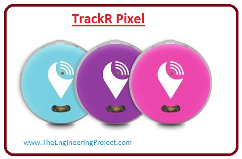
TrackR Pixel
- For the most part, there are two levels of losing an item. It’s either just misplaced or left in a public area.
- If you can’t remember where’s the last spot you had your item, then the TrackR Pixel will aid you in that situation.
- Since this product is small, you can fasten it to almost anything, such as luggage, bags, wallets, or keys.
- With the help of the TrackR application on your phone, you’ll know the last known spot of the item you’re tracking.
- Also, there is the Global Crowd Locate feature that will help you even more if you cannot recover the lost item at your home.
- Other users of the product all over the world will aid you in tracking the item for you.
SpotyPal
- If you’re worried about the battery life of your tracking device, then the SpotyPal could help you out.
- This product has a low-energy usage. Therefore, its battery can last at least a year.
- Plus, replacing batteries would be the least of your concerns.
Takeaway
- Do you find it hard to look for your valuable items when it goes missing? May it be as small as your keys or as big as your laptop.
- Nevertheless, you might be needing a Bluetooth tracker.
- Within a small span of time, you can find your things.
It is the detailed article on the Best Bluetooth trackers if you have any question ask in comments. Thanks for reading. Take care until the next tutorial.
Types and Usage of the Slip Rings
Hello friends, I hope you all are doing great. In today’s tutorial, we will discuss the
Types and Usage of the Slip Rings.
Slip rings are an essential part of any system that has or does rotation as a part of working. At the center of any automation system, an electric slip ring is responsible for the transmission of current from a static device to a rotating one. They are used almost with every machine that requires power and data connectivity. It is because of this reason slip rings have a significant impact on equipment consistency, action, and performance.
Slip rings enrich the mechanical-performance of the mechanism, modernize system utility, and eliminate damage-prone wires dangling from revolving joints. Slip rings are also known as rotatory linkages, swivels, and commutates. A slip ring encompasses brush blocks, which are coordinated and available as a pair of the ring and a brush.
These days almost every product has a slip ring in them. There are all kinds of the slip rings available in the market like collecting ring, high-speed slip ring, disk electric conduction slip ring and many more. Each slip ring has a different purpose and use. In today's post, we will have a look at different types of slip rings and their uses. So let's get started with the
Types and Usage of the Slip Rings.
Types and Usage of the Slip Rings
Wireless Slip Rings
- They don’t rely on procedures approved using carbon contact brush and resistance based metal in slip rings.
- As an alternative, they rely on the transformation of data and power wirelessly utilizing the electromagnetic field.
- It is produced using the coils that are positioned in a revolving receiver and immobile receiver.
- They are considered as an additional for traditional slip ring they are easy to conserve and can withstand in an unforgiving environment.
Pancake Slip Rings
- In the pancake slip ring, electrodes are located on the flat disc. They are the kind of concentric rings that are positioned at the inner of the rotating shaft.
- This arrangement possesses a high burden and advanced capacitance and gathers wear remain on its vertical axis proficiently.
- In some situations, it has condensed axial length which is demonstrated to be suitable for some applications.
Mercury Wetted – Slip Rings
- They are distinguished for their steady connection and their low-slung resistance.
- Here sliding brush contact is substituted by a pool of liquid metal that is confined to links.
- During the spin, the liquid metal starts a linkage amongst a rotating and immobile contact.
- The decision has to be made sensibly while choosing valuable metal contacts when slip ring applications contain food manufacturing goods and pharm equipment.
Pneumatic slip ring
- This slip ring is used to transport pneumatic pressure or void from a static inlet to a rotating outlet. Meanwhile stabilizing and separating the liquid connection while rotating 360.
- Pneumatic slip rings mostly used in commercial and industrial plants equipment, off-shore drilling rigs and geotechnical tools.
Fiber Optic Slip Rings
- Also known as Fiber Optic Rotatory Joints, they are to pass signals across spinning interfaces when a large amount of data is being transmitted.
- Fiber optic Rotatory Joints maintain essential benefits of fiber from end to end.
- They are mainly used to transmit two way and four-way fiber optic connectors. Because of this, the design should be carefully crafted as the fiber's diameter is small moreover single-mode fiber's diameter is just 9nm.
- Hence the design should maintain precision which makes it challenging to process the structure of the product.
USB Slip Rings
- USB slip rings are used to get a USB signal from the static part to the moving part when it is moving 360 continuously.
- At the same time, it also assures that the USB wires don't become twisted with each other.
- These USB slip rings are used in King USB device, equipment of USB among many other things.
Ethernet Slip Rings
- Ethernet slip rings are a revolving electrical device the purpose of which is to transfer power while controlling circuits or data from static inlets to revolving outlets.
- Their innovative design meets the requirements of matching impedance, reducing losses and controlling crosstalk.
Large Current Slip Ring
- Large current slip rings are used to transmit high power and large current from a static part to a revolving one.
- While doing that they preserve and isolate the electrical connection. They also function as revolving connectors when a high amount of current it requires.
- Also, they are well suited when used as heating elements.
Miniature Slip Rings
- These are small slip rings designed to meet the requirements of small devices in which there is a need to transfer power and signal from an immobile to the revolving component.
- Given their small size they are ideal for electrical devices like sensors, video transmitters, and control panels.
- They are especially fit for rotating systems which require low controlling signals.
Waterproof Slip Rings
- The waterproof slip rings are used in an environment where there is a presence of moisture, corrosion and in underwater systems.
- Conferring to the operational environment, the waterproof slip ring could be classified into various fortification grades, such as IP65, IP67, IP68 and many more.
- The protective design and material assortment for the slip ring is connected with usage in an environment where there are liquid ingredients, such as seawater, freshwater, oil, etc.
Capsule Slip Rings
- They are best used for applications where signal and power transmission is required. Also where a compressed footprint along with the low cost is essential.
- They are a blend of concentrated scope and high function making them perfect for video and other stimulating transmissions in which space is critical.
- They use gold-on gold connects to assure longer-lasting, low noise and reduced interference which makes them perfect for transmitting video signals in applications like CCTV.
Slip rings are one of the most crucial parts of an automatic system that has a rotating motion. Hence their performance directly relates to the consistency of the whole system which runs even during routine operations.
So, it is the detailed article on the types and usage of the slip ring, if you have any question about slip ring ask in comments. Thanks for reading. Take care until the next tutorial.