How to Control DC Motor with Raspberry Pi 3

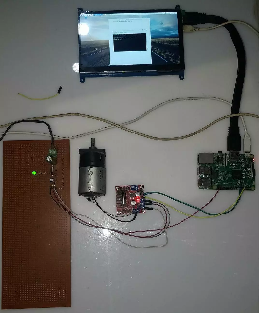
Hello friends, I hope you all are doing great. In today's tutorial, I am going to show you How to Control DC Motor with Raspberry Pi 3. We will control both the speed and direction of DC Motor. I hope you have read the previous tutorial on How to Create a GUI in Raspberry Pi 3 as we are gonna create a small GUI in this tutorial as well and then we are gonna control our DC Motor with Buttons on GUI.

In order to control the DC Motor, we have to use some drivers in between our Microcontroller and DC Motor. This driver's functionality is to control a 12V DC Motor with a 5V signal from a microcontroller. In today's tutorial, we are gonna use L298 Motor Driver. So, let's get started with How to Control DC Motor with Raspberry Pi 3:

How to Control DC Motor with Raspberry Pi 3

  • I have divided this tutorial into four parts, which are:
    • Designing of 5V Power Supply.
    • L298 Motor Driver Circuit Designing.
    • Direction Control of Dc Motor with Raspberry Pi 3.
    • Speed Control of DC Motor with Raspberry Pi 3.
  • You can download this python File for Controlling of DC Motor with Raspberry Pi 3, by clicking the below button:
Download Python File
  • So, let's first design our 5V Power Supply:

1. Designing of 5V Power Supply

  • First of all, we need to design a power supply using Voltage Regulator 7805, which will step down our voltage from 12V to 5V.
  • We need 12V for our DC Motor and 5V is also required for L298 Motor Driver.
  • I am using a 12V adapter so I need to step down this voltage to 5V.
  • You can use 5V from Raspberry Pi as well if you don't wanna design this power supply, although it's quite simple.
  • For example, if you are designing some robot then you can't place your Laptop on it. In such cases we need to design 5V power supply for our Pi.
  • Here's the list of components that are going to be used for this power supply:
    • 7805.
    • 100uF Capacitor.
    • 1000uF Capacitor.
    • 1k ohm Resistance.
    • 2 Pin Socket.
    • Male Header Pins.
  • You can see in above figure that we have used 12V Battery and then used 7805 to get 5V at the output.
  • Here's the real circuit which I have designed on wero board:
  • So, now we have all three voltage levels, which are:
    • 12V: White wire.
    • 5V: Gray Wire.
    • GND ( 0V ): Red Wire.
  • The next thing we need to do is, we need to design the Motor driver circuit using L298 Motor Driver:

L298 Motor Driver Circuit

  • L298 is an excellent motor driver, you can control two DC Motors with one L298 driver.
  • I have used L298 Motor Driver Shield, you can read more about this shield on L298 Motor Driver Library for Proteus.
  • Here's the circuit, which I have designed for controlling my DC Motor with Raspberry Pi 3:
  • You can quite easily design this circuit as you just need to connect simple jumper wires.
  • Here's my real setup with L298 Motor Driver & Raspberry Pi 3:
  • So, now we are done with our connections and you can see in above figures that we are using these three pins of Raspberry Pi 3:
    • Pin # 12: Connected to Enable A.
    • Pin # 16: Connected to Input 1.
    • Pin # 18: Connected to Input 2.
    • The fourth wire is GND, you have to connect the GND of Raspberry Pi 3 with your power supply GND.
    • +12V & 5V are provided to the L298 motor driver from our power supply.
  • Now let's design our code in python, first, we will control the direction of DC Motor and after that, we will control its speed.

Direction Control of DC Motor with Raspberry Pi 3

  • First of all, I am gonna place three Buttons on my GUI and then I will control the direction of my DC Motor with these buttons.
  • I have already explained the code in bits in my previous tutorial LEd Blinking with Raspberry Pi 3, so I will not explain it all again but will only cover the new code.
  • So, here's our first part of code, where I have done the basic configuration of our pins and GUI:
# ************************************************************************** #
# ****                                                                  **** #
# *********** Code Designed by www.TheEngineeringProjects.com ************** #
# ****                                                                  **** #
# ************** How to Control DC Motor in Raspberry Pi 3 ***************** #
# ****                                                                  **** #
# ************************************************************************** #

# Importing Libraries

import RPi.GPIO as GPIO
import time
from tkinter import *
import tkinter.font

# Libraries Imported successfully

# Raspberry Pi 3 Pin Settings

PWMPin = 12 # PWM Pin connected to ENA.
Motor1 = 16 # Connected to Input 1.
Motor2 = 18 # Connected to Input 2.
GPIO.setwarnings(False)
GPIO.setmode(GPIO.BOARD) # We are accessing GPIOs according to their physical location
GPIO.setup(PWMPin, GPIO.OUT) # We have set our pin mode to output
GPIO.setup(Motor1, GPIO.OUT)
GPIO.setup(Motor2, GPIO.OUT)

GPIO.output(PWMPin, GPIO.LOW) # When it will start then all Pins will be LOW.
GPIO.output(Motor1, GPIO.LOW)
GPIO.output(Motor2, GPIO.LOW)

PwmValue = GPIO.PWM(PWMPin, 2000) # We have set our PWM frequency to 2000.
PwmValue.start(100) # That's the maximum value 100 %.

# Raspberry Pi 3 Pin Settings Completed

# tkinter GUI basic settings

Gui = Tk()
Gui.title("DC Motor Control with Pi 3")
Gui.config(background= "#0080FF")
Gui.minsize(800,300)
Font1 = tkinter.font.Font(family = 'Helvetica', size = 18, weight = 'bold')

# tkinter simple GUI created
  • The above code is quite easy to understand, you have seen that I have made the PWM value to maximum as I don't want to change the speed, I just want to control its directions.
  • So, now let's add the buttons and Labels on our GUI, here's the code:
Text1 = Label(Gui,text='Motor Status:', font = Font1, fg='#FFFFFF', bg = '#0080FF', padx = 50, pady = 50)
Text1.grid(row=0,column=0)

Text2 = Label(Gui,text='Stop', font = Font1, fg='#FFFFFF', bg = '#0080FF', padx = 0)
Text2.grid(row=0,column=1)

Text1 = Label(Gui,text=' ', font = Font1, fg='#FFFFFF', bg = '#0080FF', padx = 150, pady = 50)
Text1.grid(row=0,column=2)

Button1 = Button(Gui, text='Clockwise', font = Font1, command = MotorClockwise, bg='bisque2', height = 1, width = 10)
Button1.grid(row=1,column=0)

Button2 = Button(Gui, text=' Motor Stop', font = Font1, command = MotorStop, bg='bisque2', height = 1, width = 10)
Button2.grid(row=1,column=1)

Button2 = Button(Gui, text='AntiClockwise', font = Font1, command = MotorAntiClockwise, bg='bisque2', padx = 50, height = 1, width = 10)
Button2.grid(row=1,column=2)

Text3 = Label(Gui,text='www.TheEngineeringProjects.com', font = Font1, bg = '#0080FF', fg='#FFFFFF', padx = 50, pady = 50)
Text3.grid(row=2,columnspan=2)

Gui.mainloop()
  • I have used three Texts in first row, the third text is just used for padding. It's easy that way. :P
  • I have placed three buttons in the second row and in the last row we have our site's link.
  • Here's the screenshot of this GUI:
  • Now, finally, we need to add the functions for these buttons.
  • Here's the code for these functions and we need to place that code above our GUI code.
def MotorClockwise():
    GPIO.output(Motor1, GPIO.LOW) # Motor will move in clockwise direction.
    GPIO.output(Motor2, GPIO.HIGH)
    
def MotorAntiClockwise():
    GPIO.output(Motor1, GPIO.HIGH) # Motor will move in anti-clockwise direction.
    GPIO.output(Motor2, GPIO.LOW)

def MotorStop():
    GPIO.output(Motor1, GPIO.LOW) # Motor will stop.
    GPIO.output(Motor2, GPIO.LOW)
  • We have three functions here and simply by toggling the pins of our DC Motor, I have changed it direction.
  • In order to stop the DC Motor, I have simply made both the pins LOW.
  • Now run your code and if everything goes fine then you will motor will follow your command.
  • Here's the screenshot of my system in running form:
  • Here's our complete code for DC Motor Direction Control with Raspberry Pi 3, in one piece. :P
# ************************************************************************** #
# ****                                                                  **** #
# *********** Code Designed by www.TheEngineeringProjects.com ************** #
# ****                                                                  **** #
# ************** How to Control DC Motor in Raspberry Pi 3 ***************** #
# ****                                                                  **** #
# ************************************************************************** #

# Importing Libraries

import RPi.GPIO as GPIO
import time
from tkinter import *
import tkinter.font

# Libraries Imported successfully

# Raspberry Pi 3 Pin Settings

PWMPin = 12 # PWM Pin connected to ENA.
Motor1 = 16 # Connected to Input 1.
Motor2 = 18 # Connected to Input 2.
GPIO.setwarnings(False)
GPIO.setmode(GPIO.BOARD) # We are accessing GPIOs according to their physical location
GPIO.setup(PWMPin, GPIO.OUT) # We have set our pin mode to output
GPIO.setup(Motor1, GPIO.OUT)
GPIO.setup(Motor2, GPIO.OUT)

GPIO.output(PWMPin, GPIO.LOW) # When it will start then all Pins will be LOW.
GPIO.output(Motor1, GPIO.LOW)
GPIO.output(Motor2, GPIO.LOW)

PwmValue = GPIO.PWM(PWMPin, 2000) # We have set our PWM frequency to 2000.
PwmValue.start(100) # That's the maximum value 100 %.

# Raspberry Pi 3 Pin Settings Completed

# tkinter GUI basic settings

Gui = Tk()
Gui.title("DC Motor Control with Pi 3")
Gui.config(background= "#0080FF")
Gui.minsize(800,300)
Font1 = tkinter.font.Font(family = 'Helvetica', size = 18, weight = 'bold')

# tkinter simple GUI created

def MotorClockwise():
    GPIO.output(Motor1, GPIO.LOW) # Motor will move in clockwise direction.
    GPIO.output(Motor2, GPIO.HIGH)
    
def MotorAntiClockwise():
    GPIO.output(Motor1, GPIO.HIGH) # Motor will move in anti-clockwise direction.
    GPIO.output(Motor2, GPIO.LOW)

def MotorStop():
    GPIO.output(Motor1, GPIO.LOW) # Motor will stop.
    GPIO.output(Motor2, GPIO.LOW)

Text1 = Label(Gui,text='Motor Status:', font = Font1, fg='#FFFFFF', bg = '#0080FF', padx = 50, pady = 50)
Text1.grid(row=0,column=0)

Text2 = Label(Gui,text='Stop', font = Font1, fg='#FFFFFF', bg = '#0080FF', padx = 0)
Text2.grid(row=0,column=1)

Text1 = Label(Gui,text=' ', font = Font1, fg='#FFFFFF', bg = '#0080FF', padx = 150, pady = 50)
Text1.grid(row=0,column=2)

Button1 = Button(Gui, text='Clockwise', font = Font1, command = MotorClockwise, bg='bisque2', height = 1, width = 10)
Button1.grid(row=1,column=0)

Button2 = Button(Gui, text=' Motor Stop', font = Font1, command = MotorStop, bg='bisque2', height = 1, width = 10)
Button2.grid(row=1,column=1)

Button2 = Button(Gui, text='AntiClockwise', font = Font1, command = MotorAntiClockwise, bg='bisque2', padx = 50, height = 1, width = 10)
Button2.grid(row=1,column=2)

Text3 = Label(Gui,text='www.TheEngineeringProjects.com', font = Font1, bg = '#0080FF', fg='#FFFFFF', padx = 50, pady = 50)
Text3.grid(row=2,columnspan=3)

Gui.mainloop()
 
  • Now let's have a look at How to Control the Speed of our DC Motor with Raspberry Pi 3.

DC Motor Speed Control with Raspberry Pi 3

  • I'm gonna add a slider in our GUI and with the help of this slider we are gonna change the value of PWM which in turn will change the speed our DC Motor.
  • Here's the code for the slider which you need to place below our last Text.
Scale1 = Scale(Gui, from_=0, to=100, orient = HORIZONTAL, resolution = 1, command = ChangePWM)
Scale1.grid(row=2,column=2)
  • Now run your GUI and you will get something as shown in below figure:
  • Here's the code for the function which will execute when we change the slider value.
def ChangePWM(self):
    PwmValue.ChangeDutyCycle(Scale1.get())
  • Now when you will run your simulation and change the value of this slider you will feel a clear change in your DC Motor speed.
  • I will also create a video which will give you better understanding of this project.
  • Here's our final combined code which will control both speed & direction of our DC Motor.
# ************************************************************************** #
# ****                                                                  **** #
# *********** Code Designed by www.TheEngineeringProjects.com ************** #
# ****                                                                  **** #
# ************** How to Control DC Motor in Raspberry Pi 3 ***************** #
# ****                                                                  **** #
# ************************************************************************** #

# Importing Libraries

import RPi.GPIO as GPIO
import time
from tkinter import *
import tkinter.font

# Libraries Imported successfully

# Raspberry Pi 3 Pin Settings

PWMPin = 12 # PWM Pin connected to ENA.
Motor1 = 16 # Connected to Input 1.
Motor2 = 18 # Connected to Input 2.
GPIO.setwarnings(False)
GPIO.setmode(GPIO.BOARD) # We are accessing GPIOs according to their physical location
GPIO.setup(PWMPin, GPIO.OUT) # We have set our pin mode to output
GPIO.setup(Motor1, GPIO.OUT)
GPIO.setup(Motor2, GPIO.OUT)

GPIO.output(PWMPin, GPIO.LOW) # When it will start then all Pins will be LOW.
GPIO.output(Motor1, GPIO.LOW)
GPIO.output(Motor2, GPIO.LOW)

PwmValue = GPIO.PWM(PWMPin, 2000) # We have set our PWM frequency to 2000.
PwmValue.start(100) # That's the maximum value 100 %.

# Raspberry Pi 3 Pin Settings Completed

# tkinter GUI basic settings

Gui = Tk()
Gui.title("DC Motor Control with Pi 3")
Gui.config(background= "#0080FF")
Gui.minsize(800,300)
Font1 = tkinter.font.Font(family = 'Helvetica', size = 18, weight = 'bold')

# tkinter simple GUI created

def MotorClockwise():
    GPIO.output(Motor1, GPIO.LOW) # Motor will move in clockwise direction.
    GPIO.output(Motor2, GPIO.HIGH)
    
def MotorAntiClockwise():
    GPIO.output(Motor1, GPIO.HIGH) # Motor will move in anti-clockwise direction.
    GPIO.output(Motor2, GPIO.LOW)

def MotorStop():
    GPIO.output(Motor1, GPIO.LOW) # Motor will stop.
    GPIO.output(Motor2, GPIO.LOW)
    
def ChangePWM(self):
    PwmValue.ChangeDutyCycle(Scale1.get())

Text1 = Label(Gui,text='Motor Status:', font = Font1, fg='#FFFFFF', bg = '#0080FF', padx = 50, pady = 50)
Text1.grid(row=0,column=0)

Text2 = Label(Gui,text='Stop', font = Font1, fg='#FFFFFF', bg = '#0080FF', padx = 0)
Text2.grid(row=0,column=1)

Text1 = Label(Gui,text=' ', font = Font1, fg='#FFFFFF', bg = '#0080FF', padx = 150, pady = 50)
Text1.grid(row=0,column=2)

Button1 = Button(Gui, text='Clockwise', font = Font1, command = MotorClockwise, bg='bisque2', height = 1, width = 10)
Button1.grid(row=1,column=0)

Button2 = Button(Gui, text=' Motor Stop', font = Font1, command = MotorStop, bg='bisque2', height = 1, width = 10)
Button2.grid(row=1,column=1)

Button2 = Button(Gui, text='AntiClockwise', font = Font1, command = MotorAntiClockwise, bg='bisque2', padx = 50, height = 1, width = 10)
Button2.grid(row=1,column=2)

Text3 = Label(Gui,text='www.TheEngineeringProjects.com', font = Font1, bg = '#0080FF', fg='#FFFFFF', padx = 50, pady = 50)
Text3.grid(row=2,columnspan=2)

Scale1 = Scale(Gui, from_=0, to=100, orient = HORIZONTAL, resolution = 1, command = ChangePWM)
Scale1.grid(row=2,column=2)

Gui.mainloop()
So, that was all for today. I hope you have enjoyed today's tutorial. Let me know if you have any questions. Have a good day. :)

What is PN Junction? Forward-Biased | Reverse-Biased

Hey Guys! I hope you all are doing great. In the previous tutorial, we studied the basics of Semiconductors, where we briefly discussed the PN Junction. Today, we are going to have a detailed overview of PN Junction.

But before getting into the details of PN Junction, we need to first recall a few concepts from the previous lecture:

Semiconductor Basics

As we know, the conductive power of a semiconductor material lies between a conductor and an insulator. So, it can act as a pure conductor as well as a pure insulator, depending on the applied conditions.

Semiconductors are divided into two types:

  • Intrinsic Semiconductor.
  • Extrinsic Semiconductor.

Intrinsic Semiconductor

  • A semiconductor in its pure form is called an Intrinsic semiconductor.
  • In this state, the outermost valance shell of the semiconductor has an equal number of electrons and holes(which is 4).
  • These four valance electrons in the outermost shell of an Intrinsic semiconductor remain bound to their positions and thus no conduction is allowed.
  • So, an Intrinsic Semiconductor acts as a pure insulator.
  • The elemental Silicon(Si) or Germanium(Ge) in its pure form is an intrinsic semiconductor.

Extrinsic Semiconductor

  • In order to increase the conductive power of semiconductors, small amounts of impurities(in the ratio of 1 to 106) are added to them, by a method called Doping.
  • Such doped/impure semiconductors are called Extrinsic Semiconductors.
  • Impurities added in the semiconductors are of two types i.e.
    • Pentavalent (Arsenic, Antimony, Phosphorous etc.).
    • Trivalent (Aluminium, Boron, Indium, Gallium etc.)
  • If the semiconductor is doped with a Pentavalent impurity, it's called N-Type Semiconductor.
  • If the doping element used is trivalent, the extrinsic semiconductor produced will be called P-Type Semiconductor.

So, now we need to understand the formation of N-Type and P-type semiconductors, because PN Junction is formed by joining these two types.

N-Type Semiconductors

  • Pure semiconductors normally belong to the 4th column of the periodic table and thus have an equal number of electrons & holes in their valance shell(which is 4).
  • So, in pure form, there's no free electron or hole available for the conduction of electricity and thus it acts as an insulator. (We discussed conduction energy levels in detail in our last lecture)
  • The pentavalent elements belong to the 5th column of the periodic table and have 5 electrons in their outermost shell.
  • So, when a pure semiconductor i.e. Silicon(Si) is doped with a pentavalent impurity i.e. Boron(B), the four valance electrons of the Boron(B) will create a covalent bond with the closest Silicon(Si) atoms, but the 5th electron won't find a pair and will become a free electron.
  • This free electron increases the conductive ability of the semiconductor.
  • As an electron carries a negative charge, such extrinsic semiconductors are called Negative-Type Semiconductors or N-Type Semiconductors.
  • In N-Type Semiconductors, the majority charge carriers are free electrons(negative), while the holes(positive) are present in very small numbers(called minority charge carriers).

Now let's have a look at the formation of P-Type Semiconductors:

P-Type Semiconductors

  • When a semiconductor is doped with a trivalent impurity i.e. Aluminium(Al), the extrinsic semiconductor produced is called P-Type Semiconductor and has positively charged holes as majority charge carriers.
  • Trivalent elements belong to the 3rd column of the periodic table and have 3 electrons in their outermost shell(valence shell).
  • So, if we dope Silicon(Si) with Aluminium(Al), the 3 valence electrons of the impurity element(Al) will create a covalent bond with the neighboring Silicon(Si) atoms.
  • The 4th valence electron of Si won't find a pair and thus a positively charged Hole will be originated. A Hole is a vacant space, has a positive charge and is ready to accommodate an electron(if available).
  • This Hole generated in the Si crystal will increase its conductivity and such doped semiconductor will be called Postive-Type Semiconductor or P-Type Semiconductor.

So far, we have created N-Type and P-Type Semiconductors by adding pentavalent and trivalent impurities respectively in separate semiconductor crystals. Now, we are going to add both impurities in a single semiconductor crystal to create a PN Junction. So let's get started:

What is PN Junction?

  • When a single crystal of semiconductor is doped with both pentavalent(i.e. Boron) and trivalent(i.e. Aluminium) impurities, a special barrier is created at the boundary of the two regions(N-Type & P-Type) which stops the flow of charge carriers. This barrier is called PN Junction.
  • The most basic semiconductor component called Diode is a real-life application of the PN Junction.

Now let's have a look at the formation of this PN Junction:

PN Junction Formation

  • As we know, electrons are the majority charge carriers in N-Type Semiconductors and Holes are the majority charge carriers in P-Type Semiconductors.
  • Now, when we dope a single Si crystal with both impurities, an N-Typer region is created on one side and a P-Type region is created on the other side of the crystal.
  • Electrons(in the N-Type region) present near the boundary get excited and diffuse into the P-Type region. Similarly, the Holes(in the P-Type region) close to the boundary move towards the N-Type region.
  • This generates a potential difference at the boundary of the two regions, which gradually increases and at one point, restricts the further flow of electrons or holes in the neighboring region. (electron-hole diffusion stops)
  • This region at the boundary with electrons in the P-Type region and Holes in the N-Type region is called the depletion region.
  • The width of this depletion region depends on the amount of impurity added to the semiconductor.
  • This Junction/boundary of the P-Type and N-Type regions is called the PN Junction.
  • Under normal conduction, when there is no voltage applied across the PN junction, the junction is said to be in an equilibrium state. The potential difference at the junction in that state is called built-in potential which is 0.7 V for Silicon(Si) and 0.3 V for Germanium(Ge).
  • When an external voltage is applied at the PN Junction, we get two behaviors of PN Junction depending on the external voltage polarity, named:
    1. Forward-Biased.
    2. Reverse-Biased.

Let's discuss these diode states, one by one:

Forward-Biased PN Junction

  • If the positive terminal of the battery is connected to the P-region and the negative terminal to the N-region, the PN Junction will be said to be operating in a Forward-Biased State.
  • The external voltage should be greater than the built-in potential i.e. 0.7V for Si and 0.3V, so that it could melt the depletion region.
  • In the Forward-Biased State, the Holes start to move towards the N-region and the electrons start flowing towards the P-region.
  • As a result, the width of the depletion region starts reducing and finally depletes out.
  • The current starts flowing through the semiconductor, as soon as the depletion region gets removed. We can say the semiconductor is acting as a conductor.
  • In this state, the semiconductor has maximum conductivity and quite low resistance.

Reverse-Biased PN Junction

  • If the P-region is connected with the negative terminal of the external source and the N-region with the positive terminal, the PN-Junction will operate in the reverse-biased state.
  • As the P-region is connected to the negative voltage, the holes in the P-region will get attracted towards the external voltage, so start flowing away from the depletion region. The same will be the case with the electrons.
  • So, no current will flow through the PN Junction in a reverse-biased state.

PN Junction as a One-Way Switch

In a normal conductive wire, current can flow in both directions but in a PN Junction, the current will flow only in one direction and will get blocked in the opposite direction. So, we can say that a PN-Junction is a One-Way Switch, allowing the current to flow in one direction only. On the top of my head, it could be used to avoid the back emf generated by the motors. This One-way switch literally bought a revolution in electronics.

Breakdown Region

  • While the PN Junction is operating in the reverse-biased state, if the external voltage exceeds a certain limit, the PN Junction will collapse, resulting in an excessive amount of current flow(short-circuit). This external voltage is called breakdown voltage and the PN Junction is said to be operating in a breakdown region.
  • PN Junction can't recover from the breakdown region so it should be avoided, though it also has a few advantages, which we will cover in the Zener Diode Chapter.
  • The breakdown voltage depends on the semiconductor used and the amount of impurity added.

Characteristic Curve of PN Junction

The following figure shows the I vs V characteristic curve of a silicon diode:

  • As we can see in the above characteristic curve of PN Junction, it has two sections i.e. forward-biased and reverse-biased.
  • In the forward-biased state, if the voltage is lower than the built-in potential(i.e. 0.7 for Si), a small amount of current is flowing through the PN Junction but if the voltage overcomes the built-in potential, the current jumps to its maximum value and we can say the PN Junction is conducting.
  • In the reverse-biased state, there's no current flowing through the PN Junction until the breakdown voltage is reached.
  • At the breakdown voltage, the current starts flowing in the opposite direction and we can say the PN Junction collapsed.
  • The small current flowing under reverse bias normal condition is known as leakage current. Germanium(Ge) has more leakage current as compared to Silicon(Si).

So, that's all for today. I hope you have enjoyed today's lecture. In the next lecture, we will discuss the Basics of Diodes, where I am going to repeat today's lecture :)) But I will keep the practical approach in it, so there will be a lot to learn. If you have any questions, you can approach me in the comment section below. Keep your suggestions and feedback coming, they help us deliver quality content. Thanks for reading the article.

Syed Zain Nasir

I am Syed Zain Nasir, the founder of <a href=https://www.TheEngineeringProjects.com/>The Engineering Projects</a> (TEP). I am a programmer since 2009 before that I just search things, make small projects and now I am sharing my knowledge through this platform.I also work as a freelancer and did many projects related to programming and electrical circuitry. <a href=https://plus.google.com/+SyedZainNasir/>My Google Profile+</a>

Share
Published by
Syed Zain Nasir