myRIO Ultrasonic Sensor Interfacing

Hello everyone! I hope you all will be absolutely fine and having fun. Today, I will give you a detailed discussion on myRIO Ultrasonic Sensor Interfacing. In this tutorial, you will learn about NI myRIO ultrasonic sensor interfacing. We will go into the details of the ultrasonic sensor and then will move forward towards its interfacing with myRIO. I have already shared many articles on ultrasonic sensors and will share their link in this article as well.

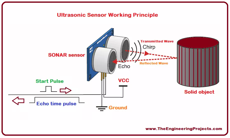
The ultrasonic sensor is also known as SONAR (Sound Navigation and Ranging). As it is clear from its name, it transmits sound waves and these waves are received back to it after getting reflected from any object. It measures the total time elapsed during the entire transmission as well as during the reception of the reflected waves. The sum of both the times is usually known as RTT (Round Trip Time). This RTT is equal to the distance between any external object and the sensor itself. Optical sensors have a transmitter for the transmission of optical waves and a receiver at the receiving end. But in comparison to an optical sensor, the SONAR sensor has a single structure for both transmission and receiving purposes.

SONAR sensor has four pins to perform different actions. It is the most common device and is specially used for obstacle avoidance purposes in robotics. It can also be used to estimate the distance of different objects. It is an inexpensive device and is easily available in the market these days. There is another sensor similar to the ultrasonic sensor available in the market named as PNG sensor. But it has three pins, that is the only difference between PNG and ultrasonic sensor. Both can be used for distance measurement and obstacle avoidance purposes. Further detail about the ultrasonic sensor and myRIO ultrasonic sensor interfacing will be provided later in this tutorial.

myRIO Ultrasonic Sensor Interfacing

An ultrasonic sensor is an electronic device/sensor/module used to estimate the distance of different objects. It works on a very simple principle. It transmits ultrasonic waves and these waves get reflected from the objects in surroundings. It receives the reflected waves and measures the time elapsed during the whole process which is equal to the distance between the specific object and the SONAR sensor. It has a wide range of applications including robot sensing, liquid level control, full detection, stacking height control, people detection for counting, presence detection, vehicle detection, thread/wire break detection etc. The ultrasonic sensor is shown in the figure given below.

Note: I have shred many tutorials on ultrasonic sensor introduction, about its libraries and its interfacing with a different microcontroller. Now, I am going to share their links again, you must go through all these articles for having a better understanding of the SONAR sensor.

Ultrasonic Sensor Pins

  • It has four pins having different individual tasks to perform.
  • Ultrasonic sensor pins are listed in the table shown in the figure below.
  • The ultrasonic sensor along with its pin names is given in the figure shown below.

Ultrasonic Sensor Pins Description

  • As we know each of them has been assigned a different task, so we should about each pin.
  • Ultrasonic sensor pins description is provided in the table given in the figure shown below.s
3. Ultrasonic Sensor Dimensions
  • The ultrasonic sensor is divided into different segments.
  • Dimensions of each segment are shown in the figure given below.
4. Ultrasonic Sensor Working Principle
  • It works on a very simple principle based on sound waves.
  • It transmits sound waves in the surroundings.
  • These sounds waves collide with the external objects.
  • After colliding with the external objects they reflect back to ultrasonic sensor.
  • It measures the total time elapsed during the transmission and receiving the reflected wave.
  • The total time is known as a Round Trip Time (RTT) and is equal to the distance between the object and the sensor.
  • That was the entire working principle of SONAR sensor.
  • I have provided the visual description of its working principle as given in the figure shown below.
5. Ultrasonic Sensor Features
  • The features of any electronic device that can make a device more popular among its competitors.
  • Ultrasonic sensor features are listed in the table shown in the figure given below.
6. Ultrasonic Sensor Ratings
  • Ratings show the voltage, power and current requirements of any electronic device.
  • Ultrasonic sensor ratings are listed in the table shown in the figure below.
7. Ultrasonic Sensor Applications
  • Electronic devices such as small sensors are usually known on the basis of their applications.
  • Ultrasonic sensor has a wide range of applications in real life.
  • Some of them are listed in the table given in the figure shown below.
8. myRIO Ultrasonic Sensor Interfacing Wiring Diagram
  • I have made a completely labelled wiring diagram for myRIO ultrasonic sensor interfacing.
  • A complete wiring diagram is given in the figure shown below.
 
9. LabVIEW Final Front Panel Design
  • As a result I have provided a complete front panel window for myRIO ultrasonic sensor interfacing.
  • The LabVIEW front panel window is given in the figure shown below.
 
  • Our team has designed this LabVIEW simulation with a lot of several testing stages.
  • After a lot of testing we got the accurate results, so we have imposed a very low cost on it.
  • But, the imposed cost is as low, that even a student can easily buy it.
In the tutorial myRIO Ultrasonic Sensor Interfacing, I have provided an environment where you can easily visualize and learn about the basics of ultrasonic sensor and its interfacing with NI myRIO. I have also shared the links of my previously shred articles for the interfacing of SONAR sensor with other micro-controllers. I hope you have enjoyed this tutorial and will appreciate my efforts. I will also share different articles on myRIO interfacing with the other sensors as well, in my upcoming tutorials. Till my next tutorial take care and bye bye :)

C# ProgressBar Control

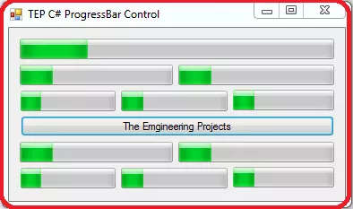
I hope you are doing good, In the tutorial, I'm going to explore C# ProgressBar Control. C# ProgressBar is used to express progress of any process. When you have to perform a long process within your desktop application then you have to use C# ProgressBar to show a user how much time left or how much progress is done. You can use C# ProgressBar for multiple purposes such as the downloading of life and result retrieving.

C# ProgressBar Control

A progress bar is used to show the progress of any process which takes a long time compared to normal processes. Mostly you have viewed these kinds of progress bar during the installation of software. C# ProgressBar has three parameters, Maximum, Minimum and the value. Maximum represents the max progress or upper range of progress and minimum represent the min progress or lower value or range, where the value is the current point of a progress bar. By default in C# ProgressBar, the value of minimum is set to zero and maximum is 100. Progress bar filled from left to right as the universal standard. You can easily drag and drop the C# ProgressBar from the GUI toolbox to your desktop application. By default, the first instance of C# ProgressBar named as the ProgressBar1. If you are wanted to preview the outcome of progress bar then you can simply set the value in the initialize phase, as you can observe in the following code we have used four progress bar with different values.
using System;
using System.Collections.Generic;
using System.ComponentModel;
using System.Data;
using System.Drawing;
using System.Linq;
using System.Text;
using System.Threading.Tasks;
using System.Windows.Forms;

namespace TEPArticle
{
    public partial class Form1 : Form
    {
        public Form1()
        {
            InitializeComponent();
            progressBar1.Value = 25;
            progressBar2.Value = 50;
            progressBar3.Value = 75;
            progressBar4.Value = 100;
        }      
    }
}
You can observe that we have used four progress bars which have values as 25, 50, 75 and 100. As you know the default value of the minimum range is zero and max range is 100 that's why we have used above values to demonstrate the states of the progress bar. In the following image, you can be observed the output of above code with progress bar states. Default instance named as progressbar1,2,3 and so on following. If you want to rename the object name of progress bar according to you then you have to visit the properties tab after selecting the relative progress bar and then change the name as you can be observed in the following image. If you are wanted to change the size of ProgressBar according to absolute values then there are two methods which you can use. The first method is, you have to select the relative ProgressBar then go to the properties tab and search for the size where you can insert the absolute values to resize the ProgressBar according to your requirements. In the following image, you can be observed the flow of actions. The second method is to do the same action with the help of programming code. We have to use the Size property and pass the values of the width and height in the constructor of Size. You can be observed the following code for better understanding.
using System;
using System.Collections.Generic;
using System.ComponentModel;
using System.Data;
using System.Drawing;
using System.Linq;
using System.Text;
using System.Threading.Tasks;
using System.Windows.Forms;

namespace TEPArticle
{
    public partial class Form1 : Form
    {
        public Form1()
        {
            InitializeComponent();
            TEPprogressBar1.Value = 25;
            TEPprogressBar1.Size = new Size(100,23);
            
        }      
    }
}
If you are looking to change the ProgressBar style then you can change that from the properties tab. There are three styles for the ProgressBar, by default its set to block and others are Continuous and Marquee. Even that you can set the ProgressBar styles from the following code.
using System;
using System.Collections.Generic;
using System.ComponentModel;
using System.Data;
using System.Drawing;
using System.Linq;
using System.Text;
using System.Threading.Tasks;
using System.Windows.Forms;

namespace TEPArticle
{
    public partial class Form1 : Form
    {
        public Form1()
        {
            InitializeComponent();
            
            TEPprogressBar1.Style = ProgressBarStyle.Blocks;
            TEPprogressBar2.Style = ProgressBarStyle.Continuous;
            TEPprogressBar3.Style = ProgressBarStyle.Marquee;

            TEPprogressBar1.Value = 25;
            TEPprogressBar2.Value = 50;
            TEPprogressBar3.Value = 75;

        }      
    }
}
We have used three progress bars, before copy, the above code inserts the three progress bar in your desktop application. Then you can be used the above code but replaced the TEPprogressBar1,2,3 with the instance names which are using for your ProgressBars. If you are wanted to make Right to left moving progress bar then you have to activate two properties for this. First, you have to make RightToLeftLayout true and then you have set RightToLeft.Yes as the value of a RightToLeft property of relative progress bar. From the following code, you can get the idea.
using System;
using System.Collections.Generic;
using System.ComponentModel;
using System.Data;
using System.Drawing;
using System.Linq;
using System.Text;
using System.Threading.Tasks;
using System.Windows.Forms;

namespace TEPArticle
{
    public partial class Form1 : Form
    {
        public Form1()
        {
            InitializeComponent();
            
            TEPprogressBar1.Style = ProgressBarStyle.Blocks;
            TEPprogressBar1.RightToLeftLayout = true;
            TEPprogressBar1.RightToLeft = RightToLeft.Yes;

            TEPprogressBar1.Value = 25;
            

        }      
    }
}
Now you can observe the above code, we have activated two properties which are compulsory to change the progress bar flow. We have also attached the Image below which is the exact output of the above code.

C# ProgressBar Event Handlers

After learning the basics, its time to move to advanced level to play with a progress bar. In C# there are several built-in functions which are known as the event handler because they only execute on specific situations. Such as you are wanted to perform any task whenever the user will click on the progress bar. Then you will use a relative event handler to tackle this situation. There are several event handlers which you can use with ProgressBar. In the following section of the article, we are going to explore each event handler to demonstrate their purpose of use.
  • C# ProgressBar Click Event Handler
  • C# ProgressBar MouseEnter Event Handler
  • C# ProgressBar MouseHover Event Handler
  • C# ProgressBar MouseLeave Event Handler
  • C# ProgressBar Resize Event Handler

C# ProgressBar Click Event Handler

This event is designed to perform functionality whenever the user will once click on the progress bar. As much time the user will click on the progress bar that much times function is executed which is declared within the braces of click event handler. Most developers used to execute the notifications and the messages on click event handler, like the warnings. First, you have to activate the click event handler for relative progress bar then you can add your functionalities with that like in the below code.
using System;
using System.Collections.Generic;
using System.ComponentModel;
using System.Data;
using System.Drawing;
using System.Linq;
using System.Text;
using System.Threading.Tasks;
using System.Windows.Forms;

namespace TEPArticle
{
    public partial class Form1 : Form
    {
        public Form1()
        {
            InitializeComponent();
            
        }

        private void TEPprogressBar1_Click(object sender, EventArgs e)
        {
            MessageBox.Show("You have clicked on the TEP ProgressBar");
        }
    }
}
In the above code, you can observe we have used the message box as the functionality which will be performed on the single click. You can declare any kind of functionality like change the color, size and value of progress bar. In the following image, there is the exact output of above code.

C# ProgressBar MouseEnter Event Handler

This event handler is used to execute any functionality when the mouse cursor enters in the boundaries of the progress bar. The visible part of the progress bar is considered as the boundaries. When you slightly enter the cursor within the visible part this event handler will get executed. You can experiment this situation by the following a code.
using System;
using System.Collections.Generic;
using System.ComponentModel;
using System.Data;
using System.Drawing;
using System.Linq;
using System.Text;
using System.Threading.Tasks;
using System.Windows.Forms;

namespace TEPArticle
{
    public partial class Form1 : Form
    {
        public Form1()
        {
            InitializeComponent();
            
        }

        private void TEPprogressBar1_MouseEnter(object sender, EventArgs e)
        {
            MessageBox.Show("MouseEnter in the TEP ProgressBar");
        }
    }
}
In the above code, you can be observed that we have used message box as the functionality within MouseEnter Event handler. So that whenever user will enter the mouse cursor within the visible part of progress bar message will get executed. Below is the exact output of the above code is attached.

C# ProgressBar MouseHover Event Handler

This event is designed to perform an action whenever the user will hover the mouse in the visible part, hovers mean to stay for a moment during movement over visible part. Until you will moving the mouse over progress bar it will not execute, you must have to stay for a while over progress bar to activate this event handler. In the following code, we have created the proper code for above scenario.
using System;
using System.Collections.Generic;
using System.ComponentModel;
using System.Data;
using System.Drawing;
using System.Linq;
using System.Text;
using System.Threading.Tasks;
using System.Windows.Forms;

namespace TEPArticle
{
    public partial class Form1 : Form
    {
        public Form1()
        {
            InitializeComponent();
            
        }
   
        private void TEPprogressBar1_MouseHover(object sender, EventArgs e)
        {
            MessageBox.Show("MouseHover in the TEP ProgressBar");
        }
    }
}
You can observe that we have used the message box as the functionality. When the MouseHover event occurs message box prompt and shows a message which is defined by the MouseHover event handler. We have also attached the output of above code which you can preview below.

C# ProgressBar MouseLeave Event Handler

This event is designed to perform functionality whenever the mouse cursor will leave the visible boundaries of ProgressBar. In short, we can be said it is the reciprocal or inverse of MouseEnter event handler. Now we are going to create the code with MouseLeave event handler. After the activation of this event handler, you have to write functionality which you want to perform within MouseLeave event handler. From the following code, you can be observed the sequence of a program which we are going to execute.
using System;
using System.Collections.Generic;
using System.ComponentModel;
using System.Data;
using System.Drawing;
using System.Linq;
using System.Text;
using System.Threading.Tasks;
using System.Windows.Forms;

namespace TEPArticle
{
    public partial class Form1 : Form
    {
        public Form1()
        {
            InitializeComponent();
            
        }

        private void TEPprogressBar1_MouseLeave(object sender, EventArgs e)
        {
            MessageBox.Show("MouseLeave the TEP ProgressBar");
        }
    }
}
In the above code, we will observe we have used the message box. So that whenever mouse cursor will leave the visible part of progress bar it will get executed. You can perform any functionality instead of message box as you are required, for this tutorial we have used the message box. In the following image, you can observe the exact output which will come after execution.

C# ProgressBar Resize Event Handler

This event handler is designed to perform whenever the size of a progress bar is get changed in any mean such as the change in width or height. Now we are going to perform this event handler. You have to place a button on which click event handler you will declare the size changed functionality for a progress bar. So that, when you will click on the button size of a progress bar, is get changed. Then we will be used the Resize event handler for a relative progress bar. When size is get changed resize progress bar get executed. You can copy the below code and execute on your computer to get a clear idea.
using System;
using System.Collections.Generic;
using System.ComponentModel;
using System.Data;
using System.Drawing;
using System.Linq;
using System.Text;
using System.Threading.Tasks;
using System.Windows.Forms;

namespace TEPArticle
{
    public partial class Form1 : Form
    {
        public Form1()
        {
            InitializeComponent();
            
        }

        private void TEPprogressBar1_Resize(object sender, EventArgs e)
        {
            MessageBox.Show("TEP ProgressBar Size is Changed Now !!");
        }

        private void button1_Click(object sender, EventArgs e)
        {
            TEPprogressBar1.Size = new Size(100, 30);
        }
    }
}
In above code, you can observe that we have used message box as the functionality to be executed within Resize event handler. Before copy the above code you must have to place the progress bar and button on your desktop application and don't forget to change their name. Following is the image of exact above code which is taken after execution. In this tutorial, we have tried to summarize the C# ProgressBar in depth. So that beginner can understand their usage in software development. After this, you are able to create your own small application in which you can reflect processing via C# ProgressBar. For further advanced topics, you can read, C# PictureBoxC# Checked ListBoxC# CheckBox, and C# RadioButton. Don't forget to share it with your friends if you found this tutorial informative.  

Introduction to Arduino Pico

Hi Friends! I welcome you on board. Happy to see you around. In this post today, I’ll walk you through the Introduction to Arduino Pico.

Arduino Pico is the world’s smallest Arduino compatible board, as said by Arduino Official Page. Because of its small size & low weight, it is normally used in autonomous projects i.e. drones, robots, quadcopters etc. where size is the real issue.

Arduino boards are introduced in modern electronics, to make projects economical and easy to design. A common man with no prior knowledge about programming can get hands-on experience with them. This smallest Pico version is readily available to turn your innovative thoughts into reality.

I suggest you read this post all the way through as I’ll detail the complete Introduction to Arduino Pico covering datasheet, pinout, features, pin description, programming and communication and applications.

Let’s get started.

Introduction to Arduino Pico

  • Arduino Pico is a small-sized(0.6" x 0.6"), breadboard-friendly and Arduino-Compatible Microcontroller board, based on Atmega32u4 Microcontroller, contains 15 pins onboard and developed by MellBell Electronics(a Canadian company confounded by MOHAMMAD MALHAS & AHMAD NABEL).
  • Leonardo compatible bootloader is pre-installed in Arduino Pico.
  • The small size of 0.6” x 0.6” and 1.1g weight is what makes it special for a range of autonomous applications i.e. quadcopters, robots, automation etc.
  • Arduino Pico comes with 8 digital input/output pins.
  • It also contains 3 analog I/O pins used for interfacing analog sensors.
  • Out of 8 digital pins, 1 Pin can also be used for generating PWM pulses and its Pin # D3.
  • Arduino Pico board operates at 5V while the input voltage ranges from 7V to 12V.
  • The maximum current rating of Arduino Pico is 40mA, so we can't attach a load drawing more current than that.
  • The board also contains one micro USB Type-B Port, a reset button and a Reset pin.
  • Arduino Pico supports two types of Communication Protocols: (We will discuss them later in detail)
    • Serial Protocol.
    • SPI Protocol.
  • The flash memory is 32KB out of which 4KB is used by Bootloader. It is the memory where the sketch is stored. (The code we compile on Arduino IDE software is called a sketch)
  • It comes with an SRAM memory of 2.5KB, it's even greater than that of UNO(where SRAM is 2KB).
  • It has a crystal oscillator of 16MHz, so it's as fast as UNO or Nano.
  • On its Kickstarter page, it's available in multiple colors(around 20 different colors).
  • Mellbell also offers an aluminum version of the board that can be used in overheated environments and applications.

Arduino Pico Datasheet

Before you apply this board to your embedded project, it’s wise to scan through the datasheet of the device that features the main characteristics of the board. You can download the datasheet of Arduino Pico by clicking the link below:

Arduino Pico Features

The following are the main features of the Arduino Pico board.
  • Based on the ATmega32u4 microcontroller,
  • Runs at a clocked frequency of 16 MHz
  • 40 mA DC current per I/O pin
  • 2.5KB of SRAM memory
  • Bootloader: Leonardo compatible
  • Reset: 1 pin
  • 3 SPI pads on the back of the board
  • 32 kB of internal Flash (4 kB used by the bootloader)
  • 8x digital I/O pins, 1x PWM channel, and 3x analog input channels.
  • The operating voltage is 5V.
  • Input voltage range = 7 to 12 V.
  • 6 x 0.6 inches size. Weight of 1.1 grams
  • Bootloader compatible with the Arduino Leonardo

Arduino Pico Pin Description

  • Hope you’ve got a sneak peek of this smallest Arduino board. In this section, we’ll detail the pin description of the pins installed on the board.

Analog Pins

  • There are 3 analog pins available on the board. These pins can get any number of values in opposed to digital pins which get only two values i.e. HIGH and LOW.

PWM Pins

  • This board incorporates one PWM channel which is employed to receive some of the analog output’s functions. When the PWM is activated, the board generates analog results with digital means.

Digital Pins

  • Total 8 digital pins are employed on the board. These pins are introduced to be configured as inputs or outputs according to the requirement. These pins remain ON or OFF. When they are in the OFF state they are in a LOW voltage state receiving 0V and they are in HIGH voltage state they receive 5V.

Atmega32u4 Pinout

  • The following figure represents the pinout diagram of Atmega32u4.

Atmega32u4 Pin Description

  • In this section, we’ll detail the pin description of each pin available on Atmega32u4.

Vcc

  • Digital voltage supply pin.

GND

  • Ground Pin.

Port B (PB7...PB0)

  • Port B is attached with pull-up resistors and is an 8-bit bidirectional I/O port. The pull up resistors are mainly employed to limit the current. This port is more efficient and contains better driving capabilities compared to other ports.
  • When the pull up resistors are activated in this port C, it will source current with port pins extremely pulled low.

Port C (PC6, PC7)

  • Port C is an 8-bit bidirectional I/O port that contains pull-up resistors.
  • When the pull up resistors are activated, Port C is used to source current with port pins extremely pulled low - Similar to Port B.

Port D (PD7..PD0)

  • Port D is a bi-directional 8-bit I/O port with pull-up resistors. When the reset condition is activated, the Port D pins are tri-stated.

Port E (PE6, PE2)

  • Only two bits PE6 and PE2 are available on the product pinout. It is an 8-bit bidirectional port that features internal pull up resistors to limit the current.

Port F (PF7..PF4, PF1,PF0)

  • Port F is a bidirectional port that serves as analog inputs for the A/D converter. Two bits PF2 and PF3 are not available on the device pinout.

D+

  • USB Full speed / Low Speed Positive Data Upstream Port. It is connected to the USB D+ connector pin employed with the serial resistor 22W.

D-

  • USB Full speed / Low Speed Negative Data Upstream Port. It must be connected to the USB D- connector pin incorporated with serial resistor 22W.

UGND

  • This is USB pads ground.

UCAP

  • USB Pads Internal Regulator Output supply voltage.

UVCC

  • USB Pads internal regulator Input supply voltage.

VBUS

It is USB VBUS monitor input.

XTAL1

  • Input to the inverting Oscillator amplifier and Input to the internal clock operating circuit.

XTAL2

  • Output from the inverting Oscillator amplifier.

RESET

  • A reset pin. When a low level applied to this pin for a longer period of time, it produces a reset. It is important to note that shorter pulses may not generate a reset.

AVCC

  • AVCC is the supply voltage pin for all the A/D Converter channels.

AREF

  • This pin is utilized as the analog reference pin for the A/D Converter.

Communication and Programming

  • The module comes with different communication protocols including I2C, and UART.
  • The UART is a serial communication protocol that carries two lines Tx and Rx where the former is a transmission line used to transfer the serial data and the latter is a receive data line used to receive the serial data.
  • The I2C is a two-wire communication protocol that contains two lines named SCL and SDA. The SCL is a serial clock line that is used for the synchronization of all data transfer over the I2C bus while SDA is a serial data line mainly used to carry the data.
  • Arduino IDE is the professional software developed by Arduino.cc that is used to program all types of Arduino Boards.
  • Connect the board through USB to the computer and test and program the board as you like better.

Arduino Pico Applications

  • Creating a wireless keyboard
  • Water level meter.
  • Health and security systems
  • Student projects
  • Embedded systems
  • Industrial automation
  • Automatic pill dispenser
It is important to note that all Arduino boards are microcontrollers but not all microcontrollers are Arduino boards. Due to its small size and easy to use functions, most people prefer Arduino boards over microcontrollers. Moreover, you don’t need to include extra peripherals while using these boards, as they come with built-in functions that don’t require the addition of external components. That’s all for today. I hope you’ve enjoyed reading this article. If you’re unsure or have any questions, you can approach me in the section below. I’d love to help you the best way I can. You’re most welcome to share your valuable feedback and suggestions around the content we share so we keep sharing quality content customized to your exact needs and requirements. Thank you for reading the article.

PCB Design Online Services for Engineering Students

Hi Friends! Hope you’re well today. I welcome you on board. Happy to see you around. In this post today, I’ll detail PCB Design Online Services for Engineering Students. 
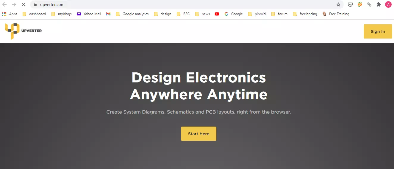
PCB designing is a crucial part of making some electrical projects. If you’re a student, you can leverage these services to design PCB online. You can design many PCB layouts for a single layer or multilayer PCB. Moreover, you can test simulation online and see how your design is working that you’re going to execute in real-time.

PCB Design Online Services for Engineering Students

You’ll find a list of online PCB design services. And I can understand, when you’re given a lot of options, it is very difficult to choose the best pick. The reason I have got you covered. In this post, I’ll detail the best PCB online services that you can get online. Some are easy to use and are better than others and give you the ability to design your PCB on the fly. These online design services are open source, which means you can leverage these services free of cost. From making single-sided PCB to multi-layer PCB and from designing complex schematic diagrams to creating final layouts, you can benefit and execute everything online. Plus, these services help you connect with renowned designers online who can give feedback on the submitted designs.
  • Know that… if you find this design process difficult, you can purchase PCB design services from outside.
  • PCBWay is a great platform to help you design a single layer or multi-layer PCBs. They incorporate a team of skilled professionals that go the extra mile to help you with your circuit design.
  • PCBWay is not a broker. They are a PCB manufacturer and PCB assembler. This means you come in direct contact with the PCB producer once you contact them online.
This was a brief introduction to the PCB services online. Let’s jump right in and elaborate further on these services.

1. Library.io

  • Library.io is a remarkable online service that helps you design PCB online. It features many components in the library, moreover, in case you don’t find the required component in the library, you can design your own.
  • As this is an online service, apart from creating your design, you can see what other designers are doing online. You can have a look at their designs and duplicate content you find useful or appropriate for your design.
  • Yes, you can duplicate design because this is an open-source service where you can design your design free of cost, and in case you need any help from skilled professionals, you can just communicate and collaborate with them and get feedback on your design.
  • You can create your design, use them in EAGLE libraries, sync them with Fusion 360, and export them for further usage in your preferred CAD system.

2. CircuitLab

CircuitLab is an online simulator for creating your PCB design. Design with your easy to use and advanced schematic editor. No installation is required and you can launch this simulator with just one click.
  • Make analog and digital simulation within a few seconds. Moreover, you can get help from professional schematic PDF files, wiring diagrams, and plots.
  • In case you find any difficulty in using this program, you can watch an introductory demo that helps you understand all nuts and bolts of this platform.
  • It is free to use and comes with scores of already made schematic diagrams and PCB layouts which give you a good starting point to initiate your design process.
  • One important thing – CircuitLab gives you the ability to make your unique circuit URL which you can use to share your designs online. And this also helps you develop your unique presence online.
  • A nice, smooth and seamless interface helps you work with multiple signals at once with configurable plotting windows, vertical and horizontal markers, and calculations on signals.

3. Upverter

  • Upverter is another amazing tool in the club – A solution for all your electrical design needs.
  • Design schematics diagrams and PCB layouts anywhere anytime right from the comfort of your home.
  • It is incorporated with popular community projects for you to review. Apart from team collaboration, you can leverage free cloud storage with simple and easy to use CAD tools.
  • Plus, the forum is also available where you can communicate and collaborate with the engineers who are working on similar designs. They will help you design your PCB layout and create schematic diagrams.
  • PCB layouts are available on the online browser where you don’t need to install any software. You can simply work with them within seconds.
  • And reverting to the previous state from the current design helps you carefully generate your layout without constantly worrying about your design.
  • And this platform keeps a full track record of the files you worked on in the past, setting you free from the safety and security of your designs.

4. EasyEDA

  • EasyEDA is an online PCB design and circuit simulator.
  • It features scores of libraries with more than 1 million real-time updated components and an integrated LCSC component catalog.
  • Plus, you can create and import your common libraries.
  • You can use this online service anywhere on your Linux, MAC, or Windows operating system.
  • This platform is hosted on several servers, giving you a fast and quick web browser, where you can save your files in the cloud server which can be easily accessed by you and anyone you authorize.
  • You can leverage hundreds of thousands of open-source private projects. From schematic capture to PCB design and libraries design to project management, this platform keeps you covered.
That’s all for today. I hope you find this post helpful. If you’re unsure or have any questions, you can pop your query in the section below. I’d love to help you the best way I can. Feel free to share your valuable suggestions and feedback around the content we share so we keep producing quality content customized to your exact needs and requirements. Thank you for reading the article.

What are Digital Latches? | SR-Latches | D-Latches

Hi mentees, we are here with a new tutorial. I hope you all are fine. So far, we have been designing combinational circuits i.e. Adder, Subtractor, Multiplexer etc. using logic gates. But from today onward, we will design sequential circuits using logic gates i.e. Latches, Flip Flops etc. Let's quickly recall what's the difference between combinational & Sequential Circuits:

Combinational Circuits:

  • Combinational circuits only use the current state of the input values to generate the output.
  • Examples of DLD Combinational Circuits are: Adders, Subtractors, Multiplexers etc.

Sequential Circuits

  • Sequential Circuits use both the current & previous states of the inputs to generate the output.
  • Examples of DLD Sequential Circuits are: Latches, Flip Flops, Timers, Counters etc.

Digital Memory Elements

Normally two types of memory elements are used in digital circuits to store binary data, named:

  • Latches
  • Flip Flops(We will cover in the next lecture)

As today's lecture is on Latches, so let's explore it:

What are Latches?

  • Latches are used in digital circuits as a memory element and are used to store/save the input states.

The two inputs of Latches are called "S" and "R" where S stands for SET and R stands for RESET. Due to inputs , latches can have four unique combinations of the input. The output is denoted as "Q" and is totally dependent on the input Combination.

Nevertheless, another Output is also used in the circuit sometimes. this output is denoted as Q' and is read as Q bar, Complement of Q or bar Q  NOT Q because it is also written as:

One can have an idea that this output is the invert result of "Q" output and depends on the Q and successively to the inputs S and R.

Two types of circuits are possible in latches:

  1. Active high circuits.
  2. Active low circuits.
Both of them are same in the Components but are different due to the arrangement of the Components. Active high circuits: In this kind of the Circuit the inputs are grounded and therefore are LOW. Latch are triggered momentary high signal. Active Low Circuits: In this kind the inputs are LOW and the latches are triggered at high signals.

TYPES OF LATCHES

Latches are classified into two main types:
  1. SR Latches
  2. D Latches.
whereas, 1st two types are further subdivided into two categories:
  1. Simple
  2. Gated
All of theses types along with the implementations are shown in figure on right side.

Prior to start  DO YOU KNOW???????

  • Logic Probes are used to give input to the circuit. They can only give two types of inputs:
  1. High ( Denoted by 1)
  2. Low ( Denoted by 0)
  • By the same token, Logic toggle show the output. There are two types of output:
  1. High ( Denoted by 1)
  2. Low ( Denoted by 0)
  • NAND gate shows the output LOW ( or 0) only when both the inputs are HIGH.
  • NOT gate show is an inverter gate.
  • NOR gate shows the output HIGH ( or 1) only when both the inputs are HIGH.

Implementation of Latches in Proteus ISIS

For best understanding, we'll design each of the type and create the truth table. Devices Required:
  1. AND Gate
  2. NOT Gate
  3. Three input AND Gate
  4. Logic Toggle
  5. Logic Probe
  6. Clock
Procedure: All the Circuits follow almost same procedure. Even so, they are different in the Construction and the characteristics.

1. SR Latches in Proteus ISIS

  • Choose Two NOR Gates and fix them on the working area.
  • Examine the Circuit diagram and arrange the other required Components according to the Circuit diagram.
  • Truss all the Components by wires with the help of circuit diagram.
  • Pop the Play button and fill the truth table.
NOTE: You can also make this Circuit with NAND Gate. Examination: The SR latch ( SET/RESET) mainly change according to the change in the S line. that means, whenever the S is HIGH the Q ( output) is shown as HIGH and vise versa.  but when both the inputs (SET & RESET)  are HIGH then we seen that both the outputs are LOW. Q ( output ) is alway the inverse of Q'. Once we check all the Conditions we can assemble our own truth table. I have made a truth table that shows us the following result:
S R Q Q’
0 0 1 0
0 1 0 1
1 0 0 1
1 1 0 1
 

2. Gated SR Latch in Proteus ISIS


The SR latch are not Complete, hence the performance can be enhanced by the a process called "Gating" , and the resultant circuit is called Gated SR Circuit.
  • We add two Positive NOR gates at the input "S" and "R" that have inverted input using NOT Gates. In this way we can examine the Condition more clearly when both the inputs in SR gate were HIGH.
  • The circuit works well when we add a clock in the two inputs of the NOR gates.
The Circuit of Gated SR is shown next: When we test the Circuit's all conditions , the output have some difference. The output here shows us the difference.  During the LOW conditions of the Circuit the output shows us the error or Latch.
CLK S R Q Q’
0 X X LATCH LATCH
1 0 0 LATCH LATCH
1 0 1 0 1
1 1 0 1 0
1 1 1 1 0

3. D Latches in Proteus ISIS

D latch is a modification of the Gated SK Latch.
  • we add the NOT Gate in advance of the RESET (R) Input and we get the circuit that looks like this:
  Accordingly to the Picture, the D  and clock are now the inputs of the Circuit and we can notice the output at Q and Q'.
CLK D Q Q’
0 0 NO CHANGE NO CHANGE
0 1 NO CHANGE NO CHANGE
1 0 0 1
1 1 1 0

4. Gated D Latch in Proteus ISIS

This is another type of D Latch.
  • Connect the clock with the D input so that  we alter the D input. But with this change, we see the changes in the output as well.
Let's have a look on the Circuit of Gated D Latch:   when we change the D and test all the Condition, the resultant truth table is:
CLK D Q Q’
0 0 0 1
0 1 1 0
1 0 1 0
1 1 0 1
Hence today we learnt about the latches, some basic concepts and its types along with  practical implementation.
Syed Zain Nasir

I am Syed Zain Nasir, the founder of <a href=https://www.TheEngineeringProjects.com/>The Engineering Projects</a> (TEP). I am a programmer since 2009 before that I just search things, make small projects and now I am sharing my knowledge through this platform.I also work as a freelancer and did many projects related to programming and electrical circuitry. <a href=https://plus.google.com/+SyedZainNasir/>My Google Profile+</a>

Share
Published by
Syed Zain Nasir