ESP32 Internal Temperature Sensor

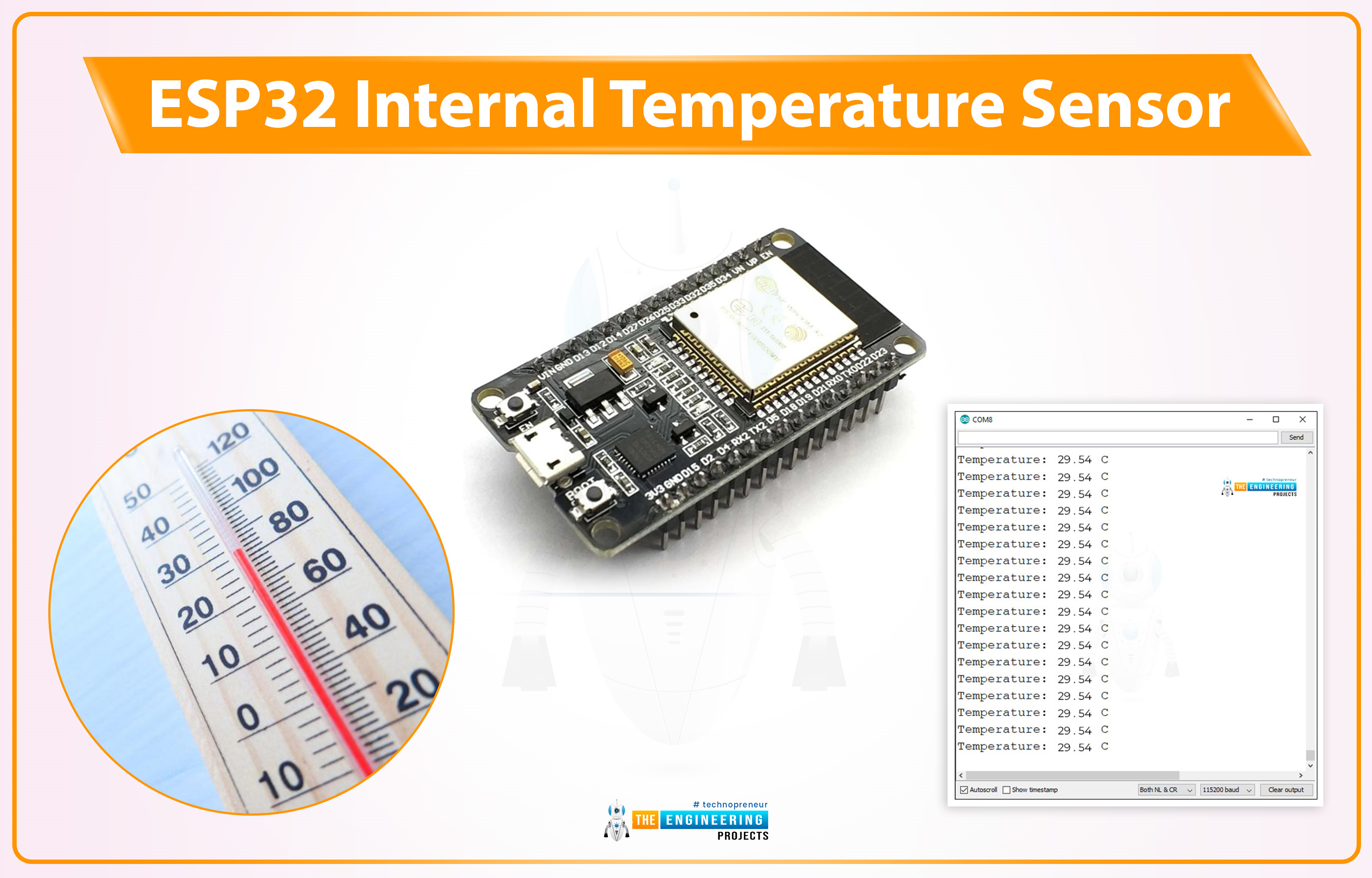
Hello friends, I hope you all are doing great. Welcome to the 3rd lecture of Section 5(ESP32 Sensors) in the ESP32 Programming Series. We have already discussed the two built-in ESP32 sensors i.e. Hall Effect Sensor and Capacitive Touch Sensor. Today, we are going to discuss the 3rd and final built-in ESP32 sensor i.e. Internal Temperature Sensor.

ESP32 Internal Temperature Sensor is used to calculate the temperature of the ESP32 core. So, we can't use it to measure the ambient temperature (the temperature of the atmosphere), for that, we need to use embedded temperature sensors i.e. DS18B20, DHT11, BMP280 etc. We will first discuss the basics of this Internal Temperature Sensor and then will design a code to monitor the change in temperature by changing the frequency of the ESP32 CPU.

Note:

  • Internal Temperature Sensor is not present in all ESP32 variants.
  • So, if ESP32 lacks the sensor, it sends an invalid temperature reading of 53.33oC(equivalent to 128 in decimal).

Important specs of the ESP32 Temperature Sensor are given in the below table:

ESP32 Temperature Sensor Features
Parameter Value
Converter Types ADC (Analog-to-Digital Converter), DAC (Digital-to-Analog Converter)
Accurate Temperature Sensing Range -40 °C to 125 °C
Suitability Good
Most Accurate Range -10 °C to 80 °C
Temperature Fluctuation Measurement High resolution
Potential Performance & Accuracy Issues Voltage fluctuations, Noise, Environmental factors, Nearby heat sources
Where To Buy?
No.ComponentsDistributorLink To Buy
1ESP32AmazonBuy Now

ESP32 Internal Temperature Sensor

ESP32’s on-chip temperature sensor cannot be used for monitoring external temperature. It can only be used to monitor the temperature of the core. This temperature sensor is available on some selective ESP32 boards and obsolete on most ESP32 variants. It has a high-temperature sensing range of -40 to 125 °C.

ESP32 boards are normally used in real-time IoT Projects i.e. home automation, back security etc. Such projects need to run 24/7 to get live updates and may heat up the motherboard. Thus, to get a stable performance in continuous operations, these internal temperature sensors are introduced to monitor the ESP32 Core.

ESP32 Boards with Built-in Temperature Sensor

Most of the modern ESP32 variants are equipped with the Internal Temperature Sensor. I have created a list of the ESP32 boards by taking the ESP-IDF documentation that caters to the built-in temperature sensor. Here's the list:

  • ESP32-C2
  • ESP32-C3
  • ESP32-C6
  • ESP32-H2
  • ESP32-S2
  • ESP32-S3

As you can see, most of the newer versions have a temperature sensor, but some older versions may also have one.

How does this temperature sensor work?

ESP32 temperature sensor consists of 2 converters:

  1. 8-bit Sigma-Delta analog-to-digital converter(ADC)
  2. digital-to-analog converter(DAC)

8-bit Sigma-Delta analog-to-digital converter (ADC)

Sigma-delta ADCs are widely favored for their exceptional accuracy and remarkable resolution, enabling them to deliver precise measurements. This ADC takes the analog signal from the temperature sensor, converts it to a digital signal and feeds it to the microcontroller for processing.

Digital-to-analog converter (DAC)

The DAC is responsible for the accuracy of the temperature measurements. It is embedded within the ESP32 and converts the digital values(converted by the Sigma-Delta ADC) again into analog values to offset any temperature-induced variation. As a result, it ensures accurate readings from the sensor.

Measuring Errors in Temperature Sensor

The accuracy of this temperature sensor changes according to the range group of the temperature values. Among different groups, the range of -10 ~ 80 is the most accurate. The reading errors along with their measuring ranges are shown in the below table:

Measuring Errors in ESP32 Temperature Sensor
No. Offset Predefined Range (°C) Error (°C) Operating Range (°C)
1 -2
50 ~ 125 < 3 Not recommended(Error)
2
-1
20 ~ 100 < 2 Ideal range for best accuracy
3
0 -10 ~ 80 < 1 Acceptable range with moderate accuracy
4
1
-30 ~ 50 < 2 Usable range with increased error at extremes
5
2
-40 ~ 20 < 3 Not recommended (error)

Different factors, including voltage fluctuations, noise, environmental factors, and nearby heat sources, can affect the performance and accuracy of this sensor.

Formula to convert observed temperature i.e. Fahrenheit to Celsius:

(F-32) *(5/9) = degree Celsius

ESP32 Temperature Sensor Applications

Here are the main applications of the ESP32 built-in temperature sensor:

Improve Chip Performance

A designer can easily monitor the internal chip’s temperature through the temperature sensor, identify bottleneck conditions, and conduct performance evaluations under extreme circumstances. So, the sensor helps in optimizing the chip's temperature and, thus, the performance.

Avoid Overheating

Electronic components/modules are sensitive, and if they are designed to work for prolonged operation, temperature management is one of the most crucial points to be considered. The built-in temperature sensor is a useful way to measure the operating temperature of the components connected to its peripherals and the whole system. These values are then utilized to set the threshold value so the system can trigger the safety mechanism when a certain heat level is passed. This can be done using the ESP32 code and surely prevent overheating to maintain the performance.

Energy Monitoring

The built-in temperature sensor helps to maintain the energy monitoring that, in turn, allows the energy monitoring of the project. The careful observation of the built-in temperature sensor output helps the user understand the relationship between temperature change and energy consumption. Using this approach, designers can target an optimized energy consumption.

Programming ESP32 to measure Core temperature in Arduino IDE

  • We are using the Arduino IDE as a compiler, we have already installed ESP32 in it, if you haven't, please read out How to Install ESP32 in Arduino IDE.
#ifdef __cplusplus
extern "C" {
    #endif
    uint8_t temprature_sens_read();
    #ifdef __cplusplus
}
#endif
uint8_t temprature_sens_read();

void setup()
{
    Serial.begin(115200);
}

void loop()
{
    Serial.print("Temperature: ");
    Serial.print(temprature_sens_read() );
    Serial.print(" F");
    Serial.print("______");

    // Convert raw temperature in F to Celsius degrees
    Serial.print((temprature_sens_read() - 32) / 1.8);
    Serial.println(" C");
    delay(1000);
}

Code Description

  • Style guard is used at the beginning to declare some function to be of “C” linkage, instead of “C++” Basically, to allow C++ code to interface with C code.
#ifdef __cplusplus
extern "C" {
    #endif
    uint8_t temprature_sens_read();
    #ifdef __cplusplus
}
#endif
uint8_t temprature_sens_read();

Setup() Function

  • Initialize the Serial monitor with a 115200 baud rate for debugging purposes.
void setup()
{
    Serial.begin(115200);
}

Loop() Function

  • Temperature_sens_read() function is used to read the temperature of the core.
  • Print the observer temperature on the serial monitor.
void loop()
{
    Serial.print("Temperature: ");
    Serial.print(temprature_sens_read() );
    Serial.print("______");
}
  • Convert the temperature from Fahrenheit to degrees Celsius and print on the serial monitor.
  • The result will be printed with a delay of 1 sec.
// Convert raw temperature in F to Celsius degrees
    Serial.print((temprature_sens_read() - 32) / 1.8);
    Serial.println(" C");
    delay(1000);

Testing/Results

  • Upload the code into the ESP32 board.
  • Open the serial monitor with a 115200 baud rate.
  • Press the EN button from the ESP32 development board.
  • See the result on the serial monitor as shown below:

This concludes the tutorial. I hope you found this of some help and also to see you soon with the new tutorial on ESP32.

Receiving Emails with ESP32 using IMAP Server

Hello readers, I hope you all are doing great. In our previous tutorial, we learned SMTP server and how to implement an SMTP server for sending emails with ESP32. In the previous tutorial, we also demonstrated some examples like sharing raw text, HTML text, images and text files.

So, at the transmitter end, we are using the SMTP server.

But, what about the receiver end?

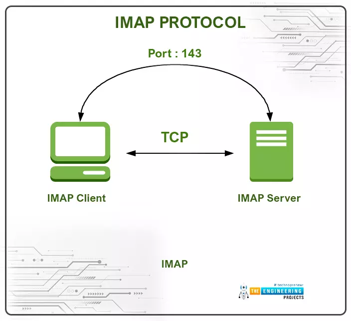
At the receiver end, we use another protocol called IMAP (or Internet Message Access Protocol) and POP3 (Post office Protocol V3) for receiving the emails.

Fig. IMAP and SMTP

Where To Buy?
No.ComponentsDistributorLink To Buy
1ESP32AmazonBuy Now

What is IMAP Protocol and How does it Work?

IMAP is an application layer (TCP/IP) protocol that is used at the receiver end to receive emails from SMTP server or mail server. IMAP follows the client/server model.

Fig. IMAP Protocol

Features of IMAP protocol:

  • IMAP can operate in three modes:
    1. Online mode
    2. Offline mode
    3. Disconnected mode
  • IMAP uses two ports:
    1. 143 Port – Communication over this port is not secure because this is a non-encrypted IMAP port.
    2. 993 Port – Communication over this port is secure and it is used when the client (IMAP) wants to connect securely through IMAP.
  • Users can access emails from a remote server without deleting the emails from the email server.
  • Setting message flag – The message flag is set to help the user in keeping the track of which message has already been seen.
  • Receivers can create a folder to organize mails in the hierarchy.
  • Users can also download a portion of a message from the mime-multi part in case of large multimedia files.
  • Organizing mail on the server.
  • Check email header – user can check the email header before downloading the mail.

What is POP3?

POP3 stands for Post Office Protocol version 3.

POP3 is another protocol to receive emails. This protocol is used to access the TCP/IP mailbox. The protocol is quite popular due to its offline mail access model.

The offline access model enables the user to access the mails from the mail server on the local machine, and then delete them from the mail server.

Why IMAP is Preferred over the POP3?

  • Being an offline access model, POP3 is not suitable for the ideal world. The biggest drawback of the POP3 model is that emails are permanently deleted from the server, and is it not possible to access the mails in different computers.
  • In POP3 user is not allowed to manage the mails on the server whilst in IMAP protocol the user can delete, create or rename the mails on the server.
  • Another drawback of the protocol is data security and safety.
  • So, a new protocol is developed to overcome the drawback of the POP3 protocol. The protocol was named Internet Message Access Protocol or IMAP. Which is an online protocol and mails received via IMAP protocol can be accessed on different computers.

Though in some applications POP3 protocol is still used, but in most of the email receivers, it is preferred to use IMAP protocol over POP3 protocol.

Setting parameters for different IMAP service provider

IMAP (incoming) setting parameter for Gmail

  • IMAP Server address – imap.gmail.com
  • IMAP username – xyz@gmail.com
  • IMAP password – password
  • IMAP port – 993

IMAP (incoming) setting parameters for Yahoo

  • IMAP Server address – mail.yahoo.com
  • IMAP username – xyz@yahoo.com
  • IMAP password – password
  • IMAP port – 993
  • SSL required – Yes

Similarly, other email service providers like Outlook and Hotmail, have different setting parameters.

  • Components required to send and receive emails using ESP32 over SMTP server are:
  • Recipient’s email address.
  • Sender’s email address.
  • Content to be shared over SMTP server.
  • ESP mail client library.
  • ESP32 module.

ESP mail client Library

To send emails with ESP32 we need to install this ESP Mail Client library. This library, make ESP32 able to send emails over SMTP server.

Step to install ESP Mail Client Library:

  • To download the ESP Mail Client Library click on the link: https://github.com/mobizt/ESP-Mail-Client
  • Open the Arduino IDE.
  • Go to Sketch >> Include Library >> Add .ZIP Library.
  • Select the downloaded ZIP file.
  • Click on

Your Arduino IDE is ready to send email using ESP32.

Create a new Gmail account

It is recommended to create a new email account for sending emails using ESP32 or ESP8266 modules.

If you are using your main (personal) email account (for sending emails) with ESP and by mistake, something goes wrong in the ESP code or programming part, your email service provider can ban or disable your main (personal) email account.

In this tutorial, we are using a Gmail account.

Follow the link to create a new Gmail account: https://accounts.google.com

Access to Less Secure apps

To get access to this new Gmail account, you need to enable Allow less secure apps and this will make you able to send emails. The link is attached below:

https://myaccount.google.com/lesssecureapps?pli=1

Fig.

Arduino IDE Code, for configuring IMAP Protocol in ESP32

  • As we mentioned earlier, we are using Arduino IDE as a compiler and upload into ESP32 module. To know more about Arduino IDE and how to use it, follow our previous tutorial i.e., on the ESP32 programming series.
  • We have already discussed installing the ESP Mail Client Library to make ESP32 able to send emails over the SMTP server.
  • This library includes multiple examples on SMTP like sending text messages, images, HTML code, text files etc. We have attached an image below for your reference.
  • You can use those examples to send emails.

Fig IMAP and SMTP Example Code

Note: You can not use the exact code. Hence, you need to make some changes like replacing SSID and password with your network credentials, email address of sender and receiver, setting IMAP and SMTP parameters for respective email service providers etc, needs to be done before uploading the code. We will also describe these things during code description.

ESP32 IMAP Code

In this code, we will implement both IMAP and SMTP protocols to receive and transmit emails.

Although, we are using SMTP in this tutorial, but we have already discussed and demonstrated the implementation on SMTP protocol in our previous tutorial. So, in this tutorial we will not explain the SMTP part.

Follow our previous tutorial for detailed study of SMTP implementation in ESP32.

#include <Arduino.h>

#include <WiFi.h>

#include <ESP_Mail_Client.h>

//To use only IMAP functions, you can exclude the SMTP from compilation, see ESP_Mail_FS.h.

#define WIFI_SSID "public"

#define WIFI_PASSWORD "ESP32@123"

//-----------setting IMAP parameters------

/* The imap host name e.g. imap.gmail.com for GMail or outlook.office365.com for Outlook */

#define IMAP_HOST "imap.gmail.com"

#define IMAP_PORT 993

#define AUTHOR_EMAIL "techeesp697@gmail.com"

#define AUTHOR_PASSWORD "Tech@ESP123"

#define RECIPIENT_EMAIL "maneesha607ece@gmail.com"

//------------setting SMTP credentials----------

#define SMTP_HOST "smtp.gmail.com"

#define SMTP_PORT 465

//------IMAP Rx emails and their status

/* Callback function to get the Email reading status */

void imapCallback(IMAP_Status status);

void printAllMailboxesInfo(IMAPSession &imap);

void printSelectedMailboxInfo(SelectedFolderInfo sFolder);

void printMessages(std::vector<IMAP_MSG_Item> &msgItems, bool headerOnly);

/* Print all attachments info from the message */

void printAttacements(std::vector<IMAP_Attach_Item> &atts);

/* The IMAP Session object used for Email reading */

IMAPSession imap;

//-------SMTP sending mails and their status----

/* The SMTP Session object used for Email sending */

SMTPSession smtp;

/* Callback function to get the Email sending status */

void smtpCallback(SMTP_Status status);


void setup()

{

Serial.begin(115200);

#if defined(ARDUINO_ARCH_SAMD)

while (!Serial)

;

Serial.println();

Serial.println("**** Custom built WiFiNINA firmware need to be installed.****\nTo install firmware, read the instruction here, https://github.com/mobizt/ESP-Mail-Client#install-custom-built-wifinina-firmware");

#endif

Serial.println();

Serial.print("Connecting to AP");

WiFi.begin(WIFI_SSID, WIFI_PASSWORD);

while (WiFi.status() != WL_CONNECTED)

{

Serial.print(".");

delay(200);

}

Serial.println("");

Serial.println("WiFi connected.");

Serial.println("IP address: ");

Serial.println(WiFi.localIP());

Serial.println();

/** Enable the debug via Serial port

* none debug or 0

* basic debug or 1

*

* Debug port can be changed via ESP_MAIL_DEFAULT_DEBUG_PORT in ESP_Mail_FS.h

*/

imap.debug(1);

/* Set the callback function to get the reading results */

imap.callback(imapCallback);

ESP_Mail_Session session;

session.server.host_name = IMAP_HOST;

session.server.port = IMAP_PORT;

session.login.email = AUTHOR_EMAIL;

session.login.password = AUTHOR_PASSWORD;

/* Setup the configuration for searching or fetching operation and its result */

IMAP_Config config;

/* Set seen flag */

//config.fetch.set_seen = true;

/* Search criteria */

config.search.criteria.clear();

/* Also search the unseen message */

config.search.unseen_msg = true;

/* Set the storage to save the downloaded files and attachments */

config.storage.saved_path = "/email_data";

config.storage.type = esp_mail_file_storage_type_flash;


config.download.header = true;

config.download.text = true;

config.download.html = true;

config.download.attachment = true;

config.download.inlineImg = true;

config.enable.html = true;

config.enable.text = true;

/* Set to enable the sort the result by message UID in the ascending order */

config.enable.recent_sort = true;

/* Set to report the download progress via the default serial port */

config.enable.download_status = true;

config.limit.search = 5;

config.limit.msg_size = 512;

config.limit.attachment_size = 1024 * 1024 * 5;

/* Connect to server with the session and config */

if (!imap.connect(&session, &config))

return;

/* {Optional} */

printAllMailboxesInfo(imap);

/* Open or select the mailbox folder to read or search the message */

if (!imap.selectFolder("INBOX"))

return;

/* {Optional} */

printSelectedMailboxInfo(imap.selectedFolder());

String uid = String(imap.getUID(imap.selectedFolder().msgCount()));

config.fetch.uid = uid;

/* Read or search the Email and close the session */

//When message was fetched or read, the /Seen flag will not set or message remained in unseen or unread status,

//as this is the purpose of library (not UI application), user can set the message status as read by set \Seen flag

//to message, see the Set_Flags.ino example.

MailClient.readMail(&imap);

/* Clear all stored data in IMAPSession object */

imap.empty();

}

void loop()

{

}

/* Callback function to get the Email reading status */

void imapCallback(IMAP_Status status)

{

/* Print the current status */

Serial.println(status.info());

/* Show the result when reading finished */

if (status.success())

{

/* Print the result */

/* Get the message list from the message list data */

IMAP_MSG_List msgList = imap.data();

printMessages(msgList.msgItems, imap.headerOnly());

/* Clear all stored data in IMAPSession object */

imap.empty();

SMTP_MSG();

}

}

void printAllMailboxesInfo(IMAPSession &imap)

{

/* Declare the folder collection class to get the list of mailbox folders */

FoldersCollection folders;

/* Get the mailbox folders */

if (imap.getFolders(folders))

{

for (size_t i = 0; i < folders.size(); i++)

{

/* Iterate each folder info using the folder info item data */

FolderInfo folderInfo = folders.info(i);

ESP_MAIL_PRINTF("%s%s%s", i == 0 ? "\nAvailable folders: " : ", ", folderInfo.name, i == folders.size() - 1 ? "\n" : "");

}

}

}

void printSelectedMailboxInfo(SelectedFolderInfo sFolder)

{

/* Show the mailbox info */

ESP_MAIL_PRINTF("\nInfo of the selected folder\nTotal Messages: %d\n", sFolder.msgCount());

ESP_MAIL_PRINTF("Predicted next UID: %d\n", sFolder.nextUID());

for (size_t i = 0; i < sFolder.flagCount(); i++)

ESP_MAIL_PRINTF("%s%s%s", i == 0 ? "Flags: " : ", ", sFolder.flag(i).c_str(), i == sFolder.flagCount() - 1 ? "\n" : "");

}

void printAttacements(std::vector<IMAP_Attach_Item> &atts)

{

ESP_MAIL_PRINTF("Attachment: %d file(s)\n****************************\n", atts.size());

for (size_t j = 0; j < atts.size(); j++)

{

IMAP_Attach_Item att = atts[j];

/** att.type can be

* esp_mail_att_type_none or 0

* esp_mail_att_type_attachment or 1

* esp_mail_att_type_inline or 2

*/

ESP_MAIL_PRINTF("%d. Filename: %s, Name: %s, Size: %d, MIME: %s, Type: %s, Creation Date: %s\n", j + 1, att.filename, att.name, att.size, att.mime, att.type == esp_mail_att_type_attachment ? "attachment" : "inline", att.creationDate);

}

Serial.println();

}

void printMessages(std::vector<IMAP_MSG_Item> &msgItems, bool headerOnly)

{

for (size_t i = 0; i < msgItems.size(); i++)

{

/* Iterate to get each message data through the message item data */

IMAP_MSG_Item msg = msgItems[i];


Serial.println("****************************");

ESP_MAIL_PRINTF("Number: %d\n", msg.msgNo);

ESP_MAIL_PRINTF("UID: %d\n", msg.UID);

ESP_MAIL_PRINTF("Messsage-ID: %s\n", msg.ID);

ESP_MAIL_PRINTF("Flags: %s\n", msg.flags);

//The attachment may not detect in search because the multipart/mixed

//was not found in Content-Type header field.

ESP_MAIL_PRINTF("Attachment: %s\n", msg.hasAttachment ? "yes" : "no");

if (strlen(msg.acceptLang))

ESP_MAIL_PRINTF("Accept Language: %s\n", msg.acceptLang);

if (strlen(msg.contentLang))

ESP_MAIL_PRINTF("Content Language: %s\n", msg.contentLang);

if (strlen(msg.from))

ESP_MAIL_PRINTF("From: %s\n", msg.from);

if (strlen(msg.sender))

ESP_MAIL_PRINTF("Sender: %s\n", msg.sender);

if (strlen(msg.to))

ESP_MAIL_PRINTF("To: %s\n", msg.to);

if (strlen(msg.cc))

ESP_MAIL_PRINTF("CC: %s\n", msg.cc);

if (strlen(msg.date))

{

ESP_MAIL_PRINTF("Date: %s\n", msg.date);

ESP_MAIL_PRINTF("Timestamp: %d\n", (int)MailClient.Time.getTimestamp(msg.date));

}

if (strlen(msg.subject))

ESP_MAIL_PRINTF("Subject: %s\n", msg.subject);

if (strlen(msg.reply_to))

ESP_MAIL_PRINTF("Reply-To: %s\n", msg.reply_to);

if (strlen(msg.return_path))

ESP_MAIL_PRINTF("Return-Path: %s\n", msg.return_path);

if (strlen(msg.in_reply_to))

ESP_MAIL_PRINTF("In-Reply-To: %s\n", msg.in_reply_to);

if (strlen(msg.references))

ESP_MAIL_PRINTF("References: %s\n", msg.references);

if (strlen(msg.comments))

ESP_MAIL_PRINTF("Comments: %s\n", msg.comments);

if (strlen(msg.keywords))

ESP_MAIL_PRINTF("Keywords: %s\n", msg.keywords);

/* If the result contains the message info (Fetch mode) */

if (!headerOnly)

{

if (strlen(msg.text.content))

ESP_MAIL_PRINTF("Text Message: %s\n", msg.text.content);

if (strlen(msg.text.charSet))

ESP_MAIL_PRINTF("Text Message Charset: %s\n", msg.text.charSet);

if (strlen(msg.text.transfer_encoding))

ESP_MAIL_PRINTF("Text Message Transfer Encoding: %s\n", msg.text.transfer_encoding);

if (strlen(msg.html.content))

ESP_MAIL_PRINTF("HTML Message: %s\n", msg.html.content);

if (strlen(msg.html.charSet))

ESP_MAIL_PRINTF("HTML Message Charset: %s\n", msg.html.charSet);

if (strlen(msg.html.transfer_encoding))

ESP_MAIL_PRINTF("HTML Message Transfer Encoding: %s\n\n", msg.html.transfer_encoding);

if (msg.rfc822.size() > 0)

{

ESP_MAIL_PRINTF("RFC822 Messages: %d message(s)\n****************************\n", msg.rfc822.size());

printMessages(msg.rfc822, headerOnly);

}

}

Serial.println();

}

}

void SMTP_MSG()

{

smtp.debug(1);

smtp.callback(smtpCallback);

ESP_Mail_Session session;

session.server.host_name = SMTP_HOST;

session.server.port = SMTP_PORT;

session.login.email = AUTHOR_EMAIL;

session.login.password = AUTHOR_PASSWORD;

session.login.user_domain = "";

/* Declare the message class */

SMTP_Message message;

message.sender.name = "The_Engineering_Projects";

message.sender.email = AUTHOR_EMAIL;

message.subject = "Auto_Response";

message.addRecipient("Maneesha", RECIPIENT_EMAIL);

//Send raw text message

String textMsg = "Thanks for contacting us. One of our client will contact you soon. www.theengineeringprojects";

message.text.content = textMsg.c_str();

message.text.charSet = "us-ascii";

message.text.transfer_encoding = Content_Transfer_Encoding::enc_7bit;

message.priority = esp_mail_smtp_priority::esp_mail_smtp_priority_low;

message.response.notify = esp_mail_smtp_notify_success | esp_mail_smtp_notify_failure | esp_mail_smtp_notify_delay;

/* Connect to server with the session config */

if (!smtp.connect(&session))

return;

/* Start sending Email and close the session */

if (!MailClient.sendMail(&smtp, &message))

Serial.println("Error sending Email, " + smtp.errorReason());

}

//-----------SMTP Status function-----

// Callback function to get the Email sending status

void smtpCallback(SMTP_Status status)

{

/* Print the current status */

Serial.println(status.info());

/* Print the sending result */

if (status.success())

{

Serial.println("----------------");

ESP_MAIL_PRINTF("Message sent success: %d\n", status.completedCount());

ESP_MAIL_PRINTF("Message sent failled: %d\n", status.failedCount());

Serial.println("----------------\n");

struct tm dt;

for (size_t i = 0; i < smtp.sendingResult.size(); i++)

{

/* Get the result item */

SMTP_Result result = smtp.sendingResult.getItem(i);

time_t ts = (time_t)result.timestamp;

localtime_r(&ts, &dt);

ESP_MAIL_PRINTF("Message No: %d\n", i + 1);

ESP_MAIL_PRINTF("Status: %s\n", result.completed ? "success" : "failed");

ESP_MAIL_PRINTF("Date/Time: %d/%d/%d %d:%d:%d\n", dt.tm_year + 1900, dt.tm_mon + 1, dt.tm_mday, dt.tm_hour, dt.tm_min, dt.tm_sec);

ESP_MAIL_PRINTF("Recipient: %s\n", result.recipients);

ESP_MAIL_PRINTF("Subject: %s\n", result.subject);

}

Serial.println("----------------\n");

}

}

Code Description

  • The first task is adding the required header files or libraries.
  • h is used to enable the Wi-Fi module and hence wireless network connectivity.
  • Another library is h to enable email services for receiving and transmitting mails over IMAP and SMTP protocols respectively.
  • Enter the network credentials in place of SSID and PASSWORD.
  • Enter the IMAP server address and port number of the respective email service provider.
  • In this code, we are using the Gmail service.
  • Enter the SMTP server address and port number of respective email service provider.

Fig. SMTP server address and port number

  • Enter your (source) email address and password details to receive and transmit emails.
  • Insert another (destination) email address.
  • imapCallback() function is used to fetch the email reading status.
  • Print the list of mailbox folders.
  • Print the information of the selected mail folder.
  • Print all the messages from the message list.
  • Print the attachment contained in the mail.
  • Call the IMAP session object which is used to read emails.
  • SMTPSession object is used for sending emails.
  • This smtpCallback() function is used to get the email sending status.
  • This function also includes printing the results like success and failure of email sent.

Setup() Code

  • Initialize the serial monitor at a 115200 baud rate for debugging purposes.
  • WiFi.begin() function is used to initialize the Wi-Fi module with Wi-Fi credentials used as arguments.
  • The While loop will continuously run until the ESP32 is connected to the Wi-Fi network.

Fig

  • If the device is connected to a local Wi-Fi network then print the details on the serial monitor.
  • WiFi.localIP() function is used to fetch the IP address.
  • Print the IP address on the serial monitor using println() function.

Fig.

  • Imap.debug(1) function is used for debugging through the serial monitor.
  • Where parameter ‘1’ represents basic debug.

Fig.

  • imap.callback() function is set to get the reading results.

Fig.

  • Declare the session configuring data.


  • Some properties of session configuration and imap_configuration accept the pointer to constant char. You can also change them to a string.
  • Set the session configuration which includes the server address of the IMAP service provider, port, and your email address and password.
  • For searching and fetching operation results set the configuration.
  • Configure the searching criteria for available information.
  • Configuration for searching unseen messages.

Fig.

  • Set the storage path to save the downloaded files.

Fig.

  • Configure the flash for storing email files.

Fig.

  • Set the message (download) header which includes text, HTML message, attachments (to store the attachments you need to enable Serial Peripheral Interface Flash File System or SPIFFS).
  • Follow our previous tutorial i.e., on sending emails with ESP32 over SMTP

  • Enable the results for HTML and text messages which are to be stored in IMAPSession object.
  • The IMAPSession object’s size is limited by config.limit.msg_size.
  • Enable.recent_sort is configured to enable the feature of sorting the messages by UID in ascending order.
  • download_status is configured to indicate the download progress on the serial monitor.
  • limit.search is configured to limit the emails in the search result.
  • The size of the message stored is limited to 512 bytes.
  • The size of attachments and images that can be downloaded is limited to 1024*1024*5bytes.
  • Connect to IMAP server with the set session and configurations.


  • Open the selected mail folder to read the received information.
  • Fetch UID from the maximum message number in mailbox and write the UID into a string type variable
  • Read the message once it is fetched.
  • Delete/clear all the data stored in the IMAPSession

imapCallback()

  • As we mentioned earlier, imapCallback() function is used to fetch the email reading status.
  • The current status is printed on the serial monitor from info() function.
  • If the email is fetched successfully, print the result and message list.
  • After that clear all the data stored in IMAPSession object.
  • SMTP_MSG() function is called when an email is fetched.
  • SMTP_MSG() function initialize the SMTP server to send an email to the destination client. This function contains all the instructions related to sending email which includes debugging, session object, message header, type of data contained in the email (raw text or HTML text), SMTP server settings, connecting to the server.
  • ESP32 will automatically send an email in reply of the mail received from the client device using this SMTP_MSG function.

Fig.

Note:- We have already discussed the SMTP server in our previous tutorial that is Sending Emails with ESP32 using SMTP server. So, follow our previous tutorial for a detailed study on SMTP protocol and send an email using ESP32.

Testing

  • After making the required changes in the given code like Wi-Fi credentials, email service provider’s details, email address of sender and receiver etc. upload the code into the ESP32 module.
  • Make sure you have turned on the access for less secure apps as discussed earlier.
  • Open the serial monitor with a 115200 baud rate.
  • Send an email to the address login in ESP32 from another email.
  • Make sure ESP32 is connected to the internet.
  • When an email is received by ESP32, the respective results are shown below :

Fig. Email received by ESP32 over IMAP

  • Once the email is fetched completely, SMTP will be initialized and an auto-response email will be sent to the destination email address.

Fig. Email successfully sent from ESP32 over SMTP


Fig. Response from ESP32

This concludes the tutorial. I hope you found this helpful and also hope to see you soon with a new tutorial on ESP32.

Sending Email with ESP32 using SMTP Protocol

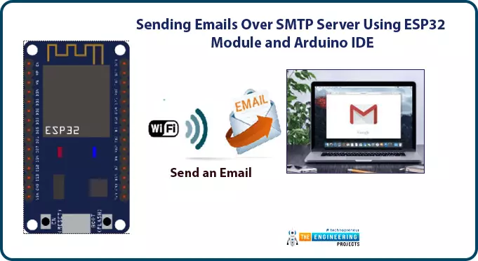
Hello readers, I hope you all are doing great. In this tutorial, we will learn how to send an email using ESP32 module. We will also learn to send text files, images or some sensor readings using the SMTP server using the ESP32 module.

In IoT (Internet of things), there are various applications where we need to send emails carrying information like sending some sensor readings, altering emails, images, text files and much more.

Where To Buy?
No.ComponentsDistributorLink To Buy
1ESP32AmazonBuy Now

What is SMTP?

SMTP or simple mail transfer protocol is an internet standard for sending and receiving electronic mail (or email) where an SMTP server receives emails from the email client.

SMTP is also used for setting communication between servers.

Various email providers like Gmail, Hotmail, Yahoo, etc. have unique SMTP addresses and port numbers.

How does SMTP work?

SMTP protocol which is also known as a push protocol is used to send emails and IMAP that is Internet Message Access Protocol (or post office protocol or POP) is used to receive emails at the receiver end.

SMTP protocol operates at the application layer of TCP/IP protocol.

When a client wants to send emails, a TCP connection will be open for the SMTP server and emails will be sent across the connection.

SMTP commands:

  • HELO – This command is sent only once per session and is used to identify the qualified domain names and the client to the server.
  • MAIL – used to initiate a message
  • RCPT – Identifies the address
  • DATA – share the data line by line

SMTP parameters for different email providers

SMTP parameters for Gmail

Gmail is the email service provided by Google and Gmail SMTP server is free to access and anyone can access this service, who has a Gmail account.

  • SMTP server: smtp.gmail.com
  • SMTP Port: 465
  • SMTP sender’s address: Gmail address
  • SMTP sender's password: Gmail Password

SMTP parameters for Yahoo

  • SMTP server: smtp.mail.yahoo.com
  • SMTP Port: 465 (with SSL)
  • Another Port number: 587 (with TLS)
  • SMTP sender’s address: email address
  • SMTP sender’s password: password

SMTP parameters for Hotmail

  • SMTP server: smtp-mail.outlook.com
  • SMTP port: 587
  • SMTP sender’s address: Hotmail email address
  • SMTP sender’s password: Hotmail password
  • SMTP TLS/SSL required : YES

SMTP parameters for Outlook

  • SMTP server: smtp-mail.office.com
  • SMTP server port for incoming mail: 993
  • SMTP server port for outgoing mail: 587
  • SMTP sender’s address: Outlook email address
  • SMTP sender’s password: Outlook password
  • SMTP TLS/SSL required : YES

Sending emails over SMTP using ESP32 in Arduino IDE

  • In this tutorial, we will demonstrate sending raw text messages and HTML messages, images, text files, etc. to the client over the SMTP server.

Components required to send and receive emails using ESP32 over SMTP server are:

  • Recipient’s email address.
  • Sender’s email address.
  • Content to be shared over SMTP server.
  • ESP mail client library.
  • ESP32 module.

ESP mail client Library

To send emails with ESP32 we need to install this ESP Mail Client library. This library, make ESP32 able to send emails over an SMTP server.

Step to install ESP Mail Client Library:

  • To download the ESP Mail Client Library click on the link given below: https://github.com/mobizt/ESP-Mail-Client
  • Open the Arduino IDE.
  • Go to Sketch >> Include Library >> Add .ZIP Library.
  • Select the downloaded ZIP file. Click on

Your Arduino IDE is ready to send email using ESP32.

Create a new Gmail account (Sender)

It is recommended to create a new email account for sending emails using ESP32 or ESP8266 modules.

If you are using your main (personal) email account (for sending emails) with ESP and by mistake, something goes wrong in the ESP code or programming part, your email service provider can ban or disable your main (personal) email account.

In this tutorial, we are using a Gmail account.

Follow the link to create a new Gmail account: https://accounts.google.com


Access to Less Secure apps

To get access to this new Gmail account, you need to enable Allow less secure apps and this will make you able to send emails. The link is: https://myaccount.google.com/lesssecureapps?pli=1

Arduino IDE Code, for sharing raw text and HTML text with ESP32 and SMTP server:
  • As we mentioned earlier, we are using Arduino IDE as a compiler and upload into the ESP32 module. To know more about Arduino IDE and how to use it, follow our previous tutorial Introduction to ESP32 Programming Series.
  • We have already discussed installing the ESP Mail Client Library to make ESP32 able to send emails over the SMTP server.
  • This library includes multiple examples on SMTP like sending text messages, images, HTML code, text files etc. We have attached an image below for your reference.
  • You can use those examples to send emails.

Fig SMTP example code

  • Note: You can not use the exact code. Hence, you need to make some changes like replacing SSID and password with your network credentials, email address of sender and receiver, SMTP setting parameters for respective email service providers etc, which need to be done before uploading the code. We will also describe these things during code description.

#include <WiFi.h>

#include <ESP_Mail_Client.h>

#define WIFI_SSID "SSID"

#define WIFI_PASSWORD "PASSWORD"

#define SMTP_HOST "smtp.gmail.com"

#define SMTP_PORT 465

/* The sign in credentials */

#define AUTHOR_EMAIL "email address"

#define AUTHOR_PASSWORD "email password"

/* Recipient's email*/

#define RECIPIENT_EMAIL "email address_Rx"

/* The SMTP Session object used for Email sending */

SMTPSession smtp;

/* Callback function to get the Email sending status */

void smtpCallback(SMTP_Status status);

void setup(){ Serial.begin(115200);

Serial.println();

Serial.print("Connecting to AP");

WiFi.begin(WIFI_SSID, WIFI_PASSWORD);

while (WiFi.status() != WL_CONNECTED){

Serial.print(".");

delay(200);

}

Serial.println("");

Serial.println("WiFi connected.");

Serial.println("IP address: ");

Serial.println(WiFi.localIP());

Serial.println();

/** Enable the debug via Serial port

none debug or 0 basic debug or 1

*/

smtp.debug(1);

/* Set the callback function to get the sending results */

smtp.callback(smtpCallback);

/* Declare the session config data */

ESP_Mail_Session session;

/* Set the session config */

session.server.host_name = SMTP_HOST; session.server.port = SMTP_PORT; session.login.email = AUTHOR_EMAIL; session.login.password = AUTHOR_PASSWORD;

session.login.user_domain = "";

/* Declare the message class */

SMTP_Message message; message.sender.name = "ESP32"; message.sender.email = AUTHOR_EMAIL; message.subject = "ESP32 Test Email";

message.addRecipient("Sara", RECIPIENT_EMAIL);

/*Send HTML message*/

String htmlMsg = "<div style=\"color:#2f4468;\"><h1>Hello CLient!</h1><p>- Sent from ESP board</p></div>"; message.html.content = htmlMsg.c_str(); message.html.content = htmlMsg.c_str(); message.text.charSet = "us-ascii";

message.html.transfer_encoding = Content_Transfer_Encoding::enc_7bit;

//Send raw text message

/* String textMsg = "Hello Client! - you have a message from ESP32 board"; message.text.content = textMsg.c_str(); message.text.charSet = "us-ascii";

message.text.transfer_encoding = Content_Transfer_Encoding::enc_7bit;*/

message.priority = esp_mail_smtp_priority::esp_mail_smtp_priority_low;

message.response.notify = esp_mail_smtp_notify_success | esp_mail_smtp_notify_failure | esp_mail_smtp_notify_delay;

/* Set the custom message header */

//message.addHeader("Message-ID: <abcde.fghij@gmail.com>");

/* Connect to server with the session config */ if (!smtp.connect(&session))

return;

/* Start sending Email and close the session */ if (!MailClient.sendMail(&smtp, &message))

Serial.println("Error sending Email, " + smtp.errorReason());

}

void loop(){

}

/* Callback function to get the Email sending status */

void smtpCallback(SMTP_Status status){

/* Print the current status */

Serial.println(status.info());

/* Print the sending result */ if (status.success()){

Serial.println("----------------");

ESP_MAIL_PRINTF("Message sent success: %d\n", status.completedCount());

ESP_MAIL_PRINTF("Message sent failled: %d\n", status.failedCount());

Serial.println("----------------\n"); struct tm dt;

for (size_t i = 0; i < smtp.sendingResult.size(); i++){

/* Get the result item */

SMTP_Result result = smtp.sendingResult.getItem(i);

time_t ts = (time_t)result.timestamp; localtime_r(&ts, &dt);

ESP_MAIL_PRINTF("Message No: %d\n", i + 1);

ESP_MAIL_PRINTF("Status: %s\n", result.completed ? "success" : "failed"); ESP_MAIL_PRINTF("Date/Time: %d/%d/%d %d:%d:%d\n", dt.tm_year + 1900,

dt.tm_mon + 1, dt.tm_mday, dt.tm_hour, dt.tm_min, dt.tm_sec); ESP_MAIL_PRINTF("Recipient: %s\n", result.recipients); ESP_MAIL_PRINTF("Subject: %s\n", result.subject);

}

Serial.println("----------------\n");

}

}

Code Description

  • The first task is adding the required header files or libraries.
  • Wifi.h is used to enable the Wi-Fi module and hence wireless network connectivity.
  • Another library is ESP_Mail_Client.h to enable email service over SMTP (simple mail transfer protocol).
  • Enter the network credentials in place of SSID and PASSWORD.
  • Insert SMTP parameter of the respective email service provider.
  • The parameters used below are for Gmail.
  • Enter the sender’s email address and password details.
  • Insert recipient’s email address.
  • SMTPSession object is used for sending emails.
  • This smtpCallback() function is used to get the email sending status.
  • This function also includes printing the results like success and failure of email sent.

Setup()

  • Initialize the serial monitor at a 115200 baud rate for debugging purposes.
  • WiFi.begin() function is used to initialize the Wi-Fi module with Wi-Fi credentials used as arguments.
  • The While loop will continuously run until the ESP32 is connected to the Wi-Fi network.

  • If the device is connected to a local Wi-Fi network then print the details on the serial monitor.
  • WiFi.localIP() function is used to fetch the IP address.
  • Print the IP address on the serial monitor using Serial.println() function.

  • Serial.debug() is used to enable the debug via Serial port where ‘0’ and ‘1’ are used as arguments where;
    • - none debug
    • - basic debug
  • Inside ESP_Mail_FS.h header file, ESP_MAIL_DEFAULT_DEBUG_PORT can be used to change the Debug port.
  • Set the smtp.callback() function to get sending results.

  • Next step is setting the message header.
  • Message header will be set inside the setup() function which includes, sender’s name, subject, sender’s email address, receiver’s email address and name.

Sending raw text message

Write the message content (raw text) in the textMsg variable which you want to share over email.

Sending HTML text

To send HTML text write the respective content in the htmlMsg variable.

  • Connect to server with session configuration using smtp.connect() function.
  • Next thing to do is, send an email to the client for that MailClient.sendMail() function is used and if mail transmission is failed then that will be printed on the serial monitor along with the reason.
  • Loop() function will remain empty.

Testing

  • Upload the Arduino IDE code in the ESP32 module.
  • Make sure the Wi-Fi network is ON to which your ESP32’s Wi-Fi module is supposed to connect.
  • Open Serial monitor with 115200 baud rate.
  • Also, make sure that you have turned ON the permission for less secure apps.

Otherwise, you won’t be able to send emails and an error will be printed on the serial monitor.

  • Press the EN button from the ESP32 development board.

  • Check receiver email inbox.

Arduino IDE code, for sending images and text files using ESP32 and SMTP server:

In this example code, we will demonstrate how to share text files and images through emails using ESP32 over the SMTP server.

But, before sharing attachments (text files or images) you need to save those files on the ESP32 filesystem (SPIFFS).

Uploading files to ESP32 Filesystem (SPIFFS)

SPIFFS stands for Serial Peripheral Interface Flash File System, which is built into the ESP32 module. This is a lightweight filesystem designed for microcontrollers with flash chips connected via SPI bus, such as the ESP32 flash memory. In this flash memory, we can write, delete, read, and close files.

  • Text files and images will be saved on ESP32 filesystem (SPIFFS) using ESP32 filesystem uploader plugin for Arduino IDE.

Installing Arduino ESP32 Filesystem Uploader:

Fig.

  • Restart the Arduino IDE.

Check if the plugin is successfully uploaded or not:

  • Open Arduino IDE. Select ESP32 development board.
  • Go to
  • Check whether this ESP32 Sketch Data Upload option is available or not. If it is available that means plugin is uploaded successfully and it is ready to upload files.

Fig.

Finally, uploading files using SPIFFS or filesystem upload:

  • In Arduino IDE, create a new Arduino sketch.
  • Save the project.
  • Go to Sketch >> Show Sketch Folder. As shown in the image below:

Fig.

  • Create a new folder named as

Fig.

  • Inside that data folder add the respective text files or images you want to share over email as shown in the image below:

Fig.

  • If you are using the example code from ESP mail-client library then the images should be named as png and text files as text_file.text.
  • After saving files inside data folder, open the Arduino IDE then go to Tools >> ESP32 Sketch Data Upload to upload the SPIFFS Image.

Fig.

A message “SPIFFS Image Uploaded” will be displayed at the bottom of Arduino IDE, once the SPIFFS image is uploaded successfully.

Fig.

Arduino IDE Code

Code is already available in ESP Mail Client Library. As shown below:

Fig.

  • You can not use the exact code.
  • Some changes like Wi-Fi credentials, email address of sender and receiver, SMTP setting parameters for respective email service providers etc, need to be done before uploading the code.

// To use send Email for Gmail to port 465 (SSL), less secure app option should be enabled. https://myaccount.google.com/lesssecureapps?pli=1

// The file systems for flash and sd memory can be changed in ESP_Mail_FS.h.

#include <Arduino.h>

#include <WiFi.h>

#include <ESP_Mail_Client.h>

#define WIFI_SSID "SSID"

#define WIFI_PASSWORD "PASSWORD"

// server address for Gmail account

#define SMTP_HOST "smtp.gmail.com"

/** The smtp port e.g.

25 or esp_mail_smtp_port_25 465 or esp_mail_smtp_port_465 587 or esp_mail_smtp_port_587

*/

#define SMTP_PORT 465

/* The log in credentials */

#define AUTHOR_EMAIL "Sender's email address"

#define AUTHOR_PASSWORD "password"

/* Recipient's email*/

#define RECIPIENT_EMAIL "receiver's email address"

/* The SMTP Session object used for Email sending */

SMTPSession smtp;

/* Callback function to get the Email sending status */

void smtpCallback(SMTP_Status status);

void setup(){

Serial.begin(115200);

Serial.println();

Serial.print("Connecting to AP");

WiFi.begin(WIFI_SSID, WIFI_PASSWORD);

while (WiFi.status() != WL_CONNECTED){

Serial.print(".");

delay(200);

}

Serial.println("");

Serial.println("WiFi connected.");

Serial.println("IP address: ");

Serial.println(WiFi.localIP());

Serial.println();

if (!SPIFFS.begin(true)) {

Serial.println("An error has occurred while mounting SPIFFS");

}

else{

Serial.println("SPIFFS mounted successfully");

}

/** Enable the debug via Serial port

  • none debug or 0
  • basic debug or 1

*/

smtp.debug(1);

/* Set the callback function to get the sending results */

smtp.callback(smtpCallback);

/* Declare the session config data */

ESP_Mail_Session session;

/* Set the session config */ session.server.host_name = SMTP_HOST; session.server.port = SMTP_PORT; session.login.email = AUTHOR_EMAIL; session.login.password = AUTHOR_PASSWORD;

session.login.user_domain = "mydomain.net";

/* Declare the message class */

SMTP_Message message;

/* Enable the chunked data transfer with pipelining for large message if server supported

*/

message.enable.chunking = true;

/* Set the message headers */ message.sender.name = "ESP Mail";

message.sender.email = AUTHOR_EMAIL;

message.subject = "Test sending Email with attachments and inline images from SD card and Flash";

message.addRecipient("Sara", RECIPIENT_EMAIL);

/** Two alternative content versions are sending in this example e.g. plain text and html */

String htmlMsg = "This message contains attachments: image and text file."; message.html.content = htmlMsg.c_str(); message.html.charSet = "utf-8";

message.html.transfer_encoding = Content_Transfer_Encoding::enc_qp;

message.priority = esp_mail_smtp_priority::esp_mail_smtp_priority_normal; message.response.notify = esp_mail_smtp_notify_success | esp_mail_smtp_notify_failure | esp_mail_smtp_notify_delay;

/* The attachment data item */

SMTP_Attachment att;

/** Set the attachment info e.g.

  • file name, MIME type, file path, file storage type,
  • transfer encoding and content encoding

*/

att.descr.filename = "image.png"; att.descr.mime = "image/png"; //binary data

att.file.path = "/image.png";

att.file.storage_type = esp_mail_file_storage_type_flash;

att.descr.transfer_encoding = Content_Transfer_Encoding::enc_base64;

/* Add attachment to the message */

message.addAttachment(att);

message.resetAttachItem(att);

att.descr.filename = "text_file.txt"; att.descr.mime = "text/plain"; att.file.path = "/text_file.txt";

att.file.storage_type = esp_mail_file_storage_type_flash;

att.descr.transfer_encoding = Content_Transfer_Encoding::enc_base64;

/* Add attachment to the message */

message.addAttachment(att);

/* Connect to server with the session config */ if (!smtp.connect(&session))

return;

/* Start sending the Email and close the session */ if (!MailClient.sendMail(&smtp, &message, true))

Serial.println("Error sending Email, " + smtp.errorReason());

}

void loop()

{

}

/* Callback function to get the Email sending status */

void smtpCallback(SMTP_Status status){

/* Print the current status */

Serial.println(status.info());

/* Print the sending result */ if (status.success()){

Serial.println("----------------");

ESP_MAIL_PRINTF("Message sent success: %d\n", status.completedCount());

ESP_MAIL_PRINTF("Message sent failled: %d\n", status.failedCount());

Serial.println("----------------\n"); struct tm dt;

for (size_t i = 0; i < smtp.sendingResult.size(); i++){

/* Get the result item */

SMTP_Result result = smtp.sendingResult.getItem(i); time_t ts = (time_t)result.timestamp;

localtime_r(&ts, &dt);

ESP_MAIL_PRINTF("Message No: %d\n", i + 1);

ESP_MAIL_PRINTF("Status: %s\n", result.completed ? "success" : "failed"); ESP_MAIL_PRINTF("Date/Time: %d/%d/%d %d:%d:%d\n", dt.tm_year + 1900,

dt.tm_mon + 1, dt.tm_mday, dt.tm_hour, dt.tm_min, dt.tm_sec);

ESP_MAIL_PRINTF("Recipient: %s\n", result.recipients);

ESP_MAIL_PRINTF("Subject: %s\n", result.subject);

}

Serial.println("----------------\n");

}

}

Code Description:

Most part of the code is similar to the previous one (that is sending raw text and HTML text), including libraries, network credentials, enabling Wi-Fi and the serial monitor, setting the email parameters of the respective email service provided. So we not explaining the complete code but, we will explain the programming part which is different than the previous one.

Setup()

  • We are initializing the SPIFFS, inside the setup() function to sore files which are to be shared over the SMTP server.
  • begin() function is used to for initializing SPIFFS.

Fig.

  • If the server supports, enable chunked data transfer with pipelining for large messages.

Fig.

  • Next, you need to create data attachments.

Fig.

  • The next thing is sending the image, for that you need to add the attachment details: filename, path, mime type, type of storage, encoding technique.
 

Fig.

  • After adding the details of the image, add the attachment to the message.

Fig.

  • To send a text file you also need to add similar details: name of the file, path, storage type, mime type and encoding technique.

Fig.

  • Add this attachment too to the message.

Testing

  • Upload the code into the ESP32 board.
  • Make sure you have selected the correct ESP32 development board and COM port.
  • Also, make sure that you have turned on the access for less secure apps for the sender’s email account as discussed earlier. Otherwise, the ESP32 will face an authentication error.
  • Turn ON the Wi-Fi with which your device is supposed to connect with.
  • Once the device is connected with the access point, it will automatically send the attachment to the receiver's email account.

Fig.

Fig.

Fig. Email Received

This concludes the tutorial; I hope you found this helpful and also hope to see you again with a new tutorial on ESP32.

Latching in Ladder Logic Programming

Hi friends! I hope you are doing well! Today we are going to learn and practice a new topic which is a very crucial technique in plc programming. the topic is called “latching”. We mean by Latching to keep the output running starting from the instance of giving a kick-off command until we hit a command to stop running of the motor. Imagine my friends, operator wants to start a motor by hitting a start push button and want the motor to keep running and leave and go for doing another task or job. And then it keeps running until the operator wants to stop it. The problem here is that, once the operator releases his hand away from the push button, the motor automatically stopped and that is not like what the operator wants to do with the motor. To clear the problem that we are going to solve, and for which we need to use the latching technique to connect a load, Figure 1 has been created for you to show the situation to make a direct connection to a motor by using a simple push-button. In this circuit, the operator needs to keep pressing the push button as long as he needs the motor to keep working. Otherwise, the motor will stop once he releases the push button. So would please think with to figure out what is the solution for that?

Fig. 1: Connecting motor to power by push button directly

Let’s try to connect the motor through a relay as it is typically in the industry. Maybe that helps us to control the way to energize the relay coil and use its contacts to start and stop the motor, Figure 2 shows how we can employ a relay to connect the motor to the power source. However, again In fig. 2, the operator still has to keep pressing the button as long as he wants the motor to keep running. This is not the best practice in real life, the operator has many jobs to do. So, he wants to give the command to commence running the motor and leave it running to perform some other tasks and then has the motor stops after the job has been done. In this case, latching is the best practice to connect the motor or any load we want it to run for a while or until complete some functions.

Fig. 2: relaying motor to DC power by hitting start push button

How does latching work?

Now, I hope you can feel the problem between our hands and sense the meaning of the word “latching”. Again, in a real-life situation, motors or any actuators can be run via relay, by energizing the relay’s coil, the contacts of the relay switches over from off to on and then connects the motor to let it starts spinning. So for running the motor, the rely on coil should be energized. However, the latching technique makes that requirements go away, instead of that, the contact that has been used for connecting the motor to power, is used to be another pathway to connect the rely on the coil to power without needing to keep pressing the start push button. WoW! What amazing solution is that! to just hit a button and then forget about it and use the contact to make like a closed-loop to have the coil connected to power forever and let the motor work forever. Ohhh!! Forever!!! How do we run the motor without stopping? Yes, you are correct. It should be a way to break that loop when we want to do stop it. we need a way to just stop the latching, to break its loop, to enable the operator to stop the motor when they need to do.

Steps to perform latching

Let’s now show you guys how we can establish and construct a complete latching circuit step by step. In the following subsections, three steps by which will be demonstrating how to complete a typical latching circuit including only push-button and relay.

Latching Step one

First of all, in a very simple circuitry which is shown in Fig. 3, the DC power lines positive and negative are connected with a push-button and relay to run a load. The positive wire in red is connected to the push button and then to the coil terminal A1 and A2, and then to the ground black wire. So now, it’s clear that when the push button is pressed it turned on and connects the circuit of the relay coil all the way to be energized. As a result, the contact of the relay is connected and now it is ready to connect the external circuit to run an actuator i.e. motor. But when the push button is released, the coil will be de-energized and the relay coil turns back to the open state and the motor is going to stop. So moving to the next step of building a latching circuit in which we aim at creating another pathway to supply the relay coil with power to forget about the push button and have it continue to run even after releasing the push button.

Fig. 3: the typical push-button and relay circuit

Latching step two

Now Fig. 4 shows the main wiring schematic of a basic latching circuit by which we indeed realize the concept and functionality of the latching technique. in the circuit, you can notice my friends that, the contact upper point and the relay upper point are connected in such a way that, it creates another pathway for energizing the relay coil without any needs to press or even touch the push-button B1. Again, when the push button B1 is pressed, the relay coil will be energized. As a result, the relay contact will be close contacted and in turn bridges point A1 to the positive red wire. Now, when the push button is released, the relay coil still has another pathway to connect to the positive wire so the relay coil will keep energized. I know now what comes out to your mind? if this configuration and schematic can put the relay coil in the loop and energize all the time by the first kick-off by hitting the start button thanks to the latching technique. The question now is, how about stopping the motor?. How to break this loop? Yes, that’s the only thing is remaining to complete a typical latching circuit.

Fig. 4: the second step of latching

Latching step three

We can name this step by ending latching. As shown in fig. 5, a normally close (NC) push-button B2 is added in the way from contact to the positive, red, power wire. Firstly, when the push button B1 is pressed, the relay coil is energized. And the contact of the coil is connected to the positive red wire as the push-button B2 is in a closed state by default. So now, it will be latching as long as the connection to the positive wire does not break. So by hitting push-button B2, it will turn out to open state and the connection to the positive wire is broken. Therefore, the relay coil will be de-energized and the latching gets to stop.

Fig. 5: Ending latching step 3

Latching in ladder logic programming

I know guys you all are waiting to come to this point to go to our lab and simulator and practice our tutorial. So now after we discussed the concept and basics of what latching is and how does it work? We now are all set to start our simulator and practice latching techniques in ladder logic programming as we used to do every tutorial.

Ladder logic without latching

Now we need to connect a simple start push button “input A” to the motor at “output” Q0.0 straight forward as in fig. 6. You can see, by pressing the input push button switch, the output motor starts spinning. But how about after releasing our hands off the start button?

Fig. 6: Before latching

Well done! Yes, exactly like what you expected, as shown in fig. 7, when the start pushbutton has been released, the motor stops immediately.

Fig. 7: the motor stops when we released the start button

Now by adding another pathway to run the motor as shown in Fig. 8, a contact from relay “output” has been used in parallel to form “OR” logic with the start push button. So, in the first place, when the start button is pressed, the output goes high and the closed contact now adds another pathway in “OR” logic.

Fig. 8: the latching effect in ladder logic example

Figure 9 shows how the closed contact that has been taken from the relay plays the role of the alternative path to connect the output to the power. So when the input start push button has been released, the closed contact of the output relay makes the connection and the output continue running. However, there is now one problem that, how to break that connection to stop the output?

Fig. 9: the latching effect after releasing the start button

The solution for having a way to shut down or break the latching connection is that, adding a normally closed (NC) push button “input B” in series as shown in fig. 10. This way enables to break the latching connection and shut down the output.

Fig. 10: adding a stop push button to end latching

So by hitting input B, the connection of latching is broken and the output stops running. But breaking the connection will make an issue if the input B is a switch like an emergency switch. The problem is that it should be returned to its normally closed state to enable the cycle to start by hitting input A or the start push button.

Fig. 11: the usage of adding stop button to end latching

By having the stop button return to the normally closed condition, the cycle can be restarted by pressing the start push button and enabling the latching once again.

Fig. 12: restarting the process by resetting the stop push button

Latching using set and reset

There is another way to perform latching of the output. The set instruction can be used to set the output to run until a reset command is met to reset the output. This is a piece of cake to latch an output by employing set and reset instructions. Let’s practice this way in the simulator. Figure 13 shows a simple ladder logic program that uses set and reset instructions to perform latching of the output. Input push-button input A is used to set the output while input push-button input B is used to reset the latch of the output.

Fig. 13: latching using set and reset technique

By hitting the input at I0.0 which is input A, the output is set to true. The question is what happens when input A becomes false?

Fig. 14: set to enable latching the output

Figure 15 answers our wondering that, even after input becomes false the output keeps energized thanks to using a set instruction. So when will see the output turns out to be false?

Fig. 15: the output keep set true even after input becomes false

After setting the output to true, it won’t become false until a reset command is used like in the example shown in fig. 16. The output is reset by input B and becomes a false state.

Fig. 16: reset to end the latching

What’s next?

I really would like to thank you guys so much to follow our tutorial till this point and I hope you have become well known for latching concepts, and how to use and utilize them to solve a real problem in real industrial life. Now let’s continue our series, learn and enjoy practicing ladder logic programming series. Our next station will be the comparator operators including equal, not equal, greater than, equal, less than, et cetera. And how to master using this operator to compare different data types and control the logic of a ladder logic program based on the results of these comparator operators.

Introduction to Vehicle Dynamics Using MATLAB

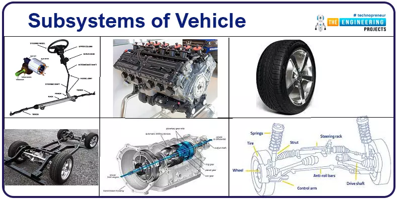
Just like the big bang theory which resulted in the world we live in. If we must mark a big bang for vehicles or the Automotive industry, it would be the invention of wheels. The invention of wheels redefined the aspects in which humans transported goods or traveled across places. Since, the invention of the wheel, transportation has always been contributing to the growth of society we live in. These vehicles later helped in conquering road travel. From its inception, the vehicle industry is technologically driven, pushing its own limits to find answers to challenges such as how can we travel faster? What will help us in making these rides more comfortable? Manually driven vehicles and their restrictions raise the need for a further quest. Quest for aspects such as,

  • How to drive these vehicles automatically?
  • How to reduce traveling time?

The second most important milestone was achieved with the invention of steam engines. Vehicles now can be driven automatically. Followed by steam engines invention of the Internal Combustion engine happened. These engines are used to convert potential energy in the form of water/heat or petrol into mechanical energy which is then transferred to wheels to move vehicles faster. In recent times there is an increased demand for vehicle safety, environmental concerns and intelligent control. Software were also introduced into vehicles to control mechanical aspects more accurately, and Electrical engines are invented to address environmental concerns. Even though we have come across a long way of invention but still there is plenty of room available for improvement as new challenges are coming across. Therefore, it is essential to understand what the vehicle is constituted of and how it will behave provided different scenarios in the outer environment.

Introduction to Vehicle Dynamics

  • Studying the behavior of vehicles or Integrated subsystems of vehicles under given circumstances is referred to as Vehicle Dynamics.

Analysis of Vehicle dynamic response requires implementing vehicles' different subsystems in the form of mathematical representation to understand different forces acting on vehicles. As these mathematical representations are quite complex, we need a tool where we can implement these equations easily and simulate them in a faster way. There are different simulators available that can help us to achieve the same.

  1. ADAMS: The multibody dynamics simulation tool, can help us study systems with multiple moving parts such as robots.
  2. Carmaker & Carsim: These tools can be used to perform analysis of vehicles using different simulations followed by tuning the parameters using the API provided.
  3. MATLAB: Since we will be implementing subsystems of vehicles ourselves, we need a tool that has the capability to represent and solve the equations very easily with its ability to handle trigonometry, linear algebra and kinematics. So, we will take the help of MATLAB to assist us in this analysis.

Along with the above benefits, MATLAB also has advanced toolboxes to understand this topic in further details.

Keywords: Vehicle Dynamics, state space, Bicycle Model, Ackerman’s criteria, OEM, ADAS, Understeer gradient.

Target Audience

Knowledge of vehicle dynamics is helpful to peruse a carrier in the tire, suspension, braking and transmission design. In the Automotive industry to develop ADAS applications. For example, Lane Keep Assist, Lane centering, Automatic cruise control and many more. So Engineering students from Computer science, electronics/electrical and mechanical branch & all those who are enthusiastic about the automotive industry can take this course.

Prerequisites

Along with basic scripting knowledge of MATLAB and Simulink, introductory knowledge of linear algebra and planar geometry will be required to understand the topics throughout. Understanding and state space representation of equations will be described while discussing the demo for each subsystem.

We will start our first lesson by identifying the most important aspects which contribute to vehicles' behavior when it’s on the move. The below section will provide more regarding them. Before explaining the subsystems of vehicles, let us understand a few terminologies involved in vehicles' motion.

  • Vehicle motion along X-Axis is called longitudinal motion, and angle across X-Axis is called roll.
  • And vehicle motion in the direction towards Y-axis is called lateral motion and angle is called Yaw

Since vehicles can travel either to the left or to the right study of motion along the Z-axis is not required to consider.

Subsystems of Vehicle

To simplify the mathematical models involved and describe concepts in their simplistic form we will focus on subsystems that are applicable to both commercial and passenger vehicles. From a broader perspective, the performance of a vehicle can be affected due to 7 different subsystems,

Figure 1: Vehicle Dynamics Subsystems

  • Road – Performance of vehicles on a different set of roads is not shown in the diagram as roads are not part of the vehicle body itself. But as they affect how the vehicles perform. We shall prepare the mathematics model and its elements involved in our study.

1. Lateral Dynamics

To understand the need for lateral dynamics let us take an example, that car is traveling on a circular road.

The force vector shown on the line of the circle can be separated into two components, one component normal to X-Axis and another along the X-axis. The amount of force along the X-axis will be responsible to pull the vehicle towards the center of the circle. Because of which driver will feel that vehicle is going outside of the road. This phenomenon was first observed in the 17th century and a study for Vehicles traveling on the circular road with constant velocity and constant steering was started. To prevent the vehicle from going out of the road, an equal amount of force is needed which will push the vehicle outwards, called centrifugal force.

This behavior in which it appears like the vehicle is going to leave the road due to less steering is called understeering. In a similar way, the oversteering phenomenon can be observed. The output of the lateral or steering subsystem decides how the vehicle will behave in the lateral direction, while in motion. The lateral dynamics of vehicles can be studied by building a kinematic model, by building meaning implementing geometric equations in MATLAB. To understand these kinematic equations we will be referring to planar geometry, where we consider vehicle motion in the (X, Y) axis.

Even if take passenger vehicle, which has 4 wheels, components involved in modeling 4 wheels are complex as the four different delta angles of wheels and their dimensions will have an impact.

Figure 2: Ackerman Criteria for Steering Angle

So, to make the initial study simpler we will make a few assumptions.

  1. Let us assume that the left and right half parts of the vehicle behave in a similar manner.
  2. The second assumption is that only front wheels can move independently, meaning steering can control the movement of front wheels (Popularly known as front-wheel-drive system). Wheels on the rear side will follow the course.

With this assumption, we can combine the left and right parts and consider that the vehicle has only two wheels one on the front side and another at the back.

This model is called a bicycle model as it looks like a bicycle. And as we can observe the complexity involved in the model is also reduced. The bicycle model has a “Two” degree of freedom (Y, ?). Where theta being angle with respect to Y-axis or Yaw of vehicle.

The assumption involved mainly considering both left-hand and right-hand side wheel takes same steering angle, hence represented with a single wheel. However, the steering angle provided to left- and right-hand side wheels are slightly different due to the radius they must cover.

As seen in the image, R corresponds to the radius to be covered resulting in the wheel angle delta provided using steering. Ackerman’s equations will help in analyzing scripted bicycle models on different curvatures. And length “a” is the length of the shaft from the center of gravity to the front wheel. “b” is the length of the driving shaft from the center of gravity to the rear wheel.

2. Longitudinal Dynamics

Just now we had introduced a subsystem of vehicles that affects the behavior of vehicles during lateral motion. Our second subsystem contributes in the longitudinal direction. As shown above, the longitudinal subsystem is made up of 3 parts.

  1. The engine generates the necessary power to drive the vehicle.
  2. Torque converter converts this power to drive mechanical components such as drive shaft, ensuring the comfort of persons sitting inside the vehicle. For example, a torque converter acts to reduce the torque transferred from the engine to the transmission unit when the driver is pressing a break.
  3. A transmission unit: Gears, clutch and torque distribution to wheels.

The torque output performance of the engine can be studied using parameterized models and maps of thrust to exhaust for every paddle position on the accelerator proposed as outputs.

2.1. Engine

The engine serves as a vehicle's power source. Understanding of engine characteristics is tightly coupled with the transmission. In layman’s term engines are characterized by power it provides generated torque at different speed or throttle/accelerator position.

Torque= Generated power X Speed of vehicle

Also, to determine acceleration performance it is important to analyze the power/weight ratio of vehicles. Which can be determined by using Newton’s second law of motion. We shall study braking performance implementing the same law of motion.

2.2. Transmission

Since vehicles may travel on a surface which is having a certain amount of slope. It is very important to ensure that the maximum amount of torque produced by the vehicle is transferred to the wheels. Gears were invented to satisfy this need. These parts having teeth are used to convert the rotational motion of the shaft to a translational one so that it can be provided to wheels. Gears are also used to change the direction of power distribution, which helps in driving a vehicle in the reverse direction.

Above are a couple of examples to understand the importance of transmission to move vehicles in the longitudinal direction. Now let us consider a case, where while traveling in turn vehicle’s outer wheel shall move faster than the inner wheel. It is because the outer wheel needs to travel more distance than the inner wheel as the radius of the curve is different.

  • Distance travelled by inner wheel = 2* Angle of travel * Rin.
  • Distance travelled by inner wheel = 2* Angle of travel * Rout.

To satisfy this constraint differential torque distribution is used by the Transmission unit. We will study how gears help in providing different torque to wheels on each side to meet this demand. This differential torque distribution can be demonstrated using the Simulink Simscape product from the MATLAB family of work products. The image is shown here, enlists a few block sets involved in modeling.

Figure 3: Simscape/Fundamental Blockset

3. Suspensions

As the basic requirements are satisfied with lateral and longitudinal dynamics. The third subsystem focuses on the comfort provided to passengers while moving. Vehicle suspension functionality is to support the body of the vehicle over its chassis. In mechanical terms suspension of a vehicle helps in defining vehicle Ride, Roll and handling. The vehicle is categorized as good or bad comfort based on two aspects. How easy the vehicle is to steer; does it provide a comfortable acceleration and braking experience to the driver.

  • Ride: For better ride comfort vehicle suspension shall isolate the body of the vehicle from the chassis so that acceleration and jerk experience reduce to its minimum.

For example, consider the vehicle is traveling at a speed of 100kph speed. And the driver applies the brake. Now due to inertia, if the vehicle stops very aggressively then it might give an uncomfortable experience to passengers sitting inside, meanwhile, it is also important to stop the vehicle at a minimum distance as possible.

  • Roll: The roll of the vehicle can define how effectively a vehicle can hold the ground at maximum lateral acceleration. It's expected that the vehicle tire on the outside shall always be grounded while corning.

To increase rolling capacity one of the mechanical methods used is “Anti Roll Bar”.

Steering Step Response or vehicle Cornering test is used where the vehicle is driven at different high speeds and the steering wheel is rotated suddenly in one direction to check if the vehicle left the ground.

  • Handling: The suspension model shall provide a comfortable braking experience when the driver applies the brake at high speed. Handling of the vehicle corresponds to the behavior of the vehicle on lateral and longitudinal sides at maximum lateral acceleration and maximum speed.

This series will focus on modeling active and passive suspension models and their differences.

4. Tires

Newton's first law states that if a body is at rest or moving at a constant speed in a straight line, it will remain at rest or keep moving in a straight line at constant speed unless it is acted upon by a force. And as tires are the point of contact to this physical world, we shall study all resultant forces acting on tires, as they will contribute the most in the direction of motion of the vehicle. Study of tire model includes,

  1. Longitudinal tire force is a force acting on the tire in the longitudinal direction, we shall prepare a tire model to understand the effect of these longitudinal forces.
  2. Effect of tire stiffness on vehicles behavior.
  3. Effect of lateral forces due to inside air pressure distribution.
  4. Finally, we will also visit the magic formula used for the tire model. The magic model is an analytical model for the relation between lateral tire force and the variables slip angle, normal force, tire-road friction coefficient and elastic tire properties.

Tires face friction with the road. And as the tire pressure inside it is not uniformly distributed, the displacement of each tire shall differ under similar circumstances. Tire modeling simply corresponds to an in-depth study of lateral and longitudinal forces acting upon the wheel when the vehicle is on move.

Parameters such as tire width, thread design, vehicle load on the tire define how tire behavior will be. One such parament thread design and its effect are explained below. Lateral Displacement:

Due to this behavior of pressure inside of the tire and its threaded manufacturing, the tire builds up with lateral force tire heads in an angle different than the angle at which the vehicle is leading. This difference in angle is called “Slip Angle”. This slip angle is shown as alpha in the image above.

5. Chassis

A good chassis design contributes to vehicles safety by absorbing forces during accidents. It is very important that drivers or passengers’ compartments in vehicles shall stay intent during the crash to protect them. Although from a manufacturing perspective there can be more aspects to look after, here in the study of dynamics, we enlist a few parameters of the vehicle which are defined by vehicle chassis.

Vehicle Length, vehicle width, front overhang, rear overhang, Front and rear axle center, the mass of vehicle etc. Front Over Hand is a distance from the front axle center to the front tip of the vehicle and the same for the rear overhand on the rear side.

Figure 4: Vehicle Parameters for Dynamic Modelling

6. Road Dynamics

To analyze the effects of different forces on vehicles on the move it is important to understand the road model. In newtons words, the road model represents forces that the vehicle shall come across to move forward with the desired speed. These forces can be classified as

  1. Forces faced by vehicle due to air
  2. Forces acting on the tire: Due to friction caused between tire and road, provided friction coefficient constant of road surface and mass of vehicle we can model friction forces applied on tires of the vehicle.

Therefore, Force produced by transmission of vehicle > Air drag + Friction force for the vehicle to move in the forward direction. In upcoming blogs, we can model the road dynamics and determine the amount of acceleration required scripting these equations in MATLAB.

Figure 5: Different Road Surfaces

Verification of Models for Results

To conclude our analysis we continue programming these subsystems in MATLAB, we also need to verify the results we obtain to confirm the model efficiency and our understanding including assumptions we will make. As these prepared dynamics models fall into two categories,

  1. MATLAB scripts to model the mathematical representation
  2. And Simulink models to demonstrate complex concepts which may take more time to model using a script.

To validate mathematical representations writing a script to control the input variables such as desired vehicle speed or curvature will help. The flow of calling “.m” files is mentioned below:

  1. load all constants and parameters
    1. run('DynamicsConstants.m');
    2. run('DynamicsParameters.m');
  2. call initial condition
  3. Call desired trajectory
  4. Simulate model
  5. Capture results and plot.

Understanding and design of vehicle model help in verification if the algorithm follows the kinematics constraint in order to make the driving experience safer and comfortable.

The second approach, the Simulink models can be validated using different inputs. One such example is to use different drive cycles to analyze the behavior of vehicles. Drive cycles contain different velocity points with respect to time. If the velocity change with respect to time is called “Modal Drive cycles”. We can conclude our analysis by observing the model’s response to these drive cycles.

Bottle Filling and Capping Project using PLC Ladder Logic

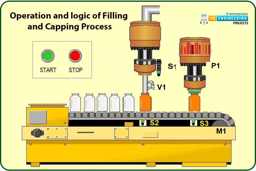
Hi friends, how are you doing? Today will integrate all of what we have learned so far in this series to build the first project based on ladder logic programming. Because we all are interested in industry, we pick one industrial project, Bottle Filling and Capping Projects, which is very common today. The problem we are going to solve today is bottle filling and capping. We have learned all basics of ladder logic including contacts and coils operation, logic gates, rising and falling edges, timers, and counters. So, today we will utilize all of these components to implement a complete ladder program of filling and capping problems.

Operation and Logic of Bottle Filling and Capping Process

For simplifying the operation of the process of filling and capping, fig. 1 shows the process flow which simply contains the main motor that drives the conveyor belt on which the bottles are running starting by hitting the start button. The conveyor belt starts running driven by motor M1 and the bottles move until sensor S2 detects one bottle, then motor M1 stops and the belt does so. At the same time, valve V1 opens to let water get dropped into the bottle until it reaches specific level thanks to level sensor S1. Then valve V1 closes and motor M1 goes on moving. Then when sensor S3 sees a bottle, the piston P1 is activated for capping the bottle and so on.

Fig. 1. The Filling and Capping Process

Process Inputs and Outputs

As you can see, for every single process in the industry, there are inputs and outputs. The inputs represent the sensors and user requests like starting and stopping the process. While the outputs are represented by actuators like motors, valves, and pistons. Table 1 lists the inputs and outputs of the filling and capping process. It shows the process consists of four inputs and three outputs including the function and description of each item.

Table 1: The list of Inputs and outputs of the Process

Logic Design of the Operation

Before going to ladder programming, we should design the logic of the operation to build guidelines on which we can develop the ladder logic. According to the operation description we stated aforementioned above, we can express the logic in lines as follows:

  • If start is ON, no filling is in progress meaning sensor S2 does not see a bottle, and no stop is requested, then motor M1 is ON.
  • If sensor S2 is ON, that means there is a bottle at a position to be filled so motor M1 will be stopped or OFF.
  • If sensor S2 is ON, that means a filling process is in progress, therefore, Valve V1 will open
  • If S1 is ON, that means the liquid in the bottle that is being filled reached the maximum level, So valve V1 closes and motor M1 now goes on running.
  • If S3 is ON, that means there is a bottle that presents at the capping station, So the piston P1 is retracted to process the capping of the bottle.

As you see in these few lines, we just wrote the philosophy of the filling and capping process’s logic. And the process keeps repeating until user requests stop. So now let’s move to convert this written logic into ladder logic rungs and enjoy for sure simulating the process in our lab to verify the logic we designed is correct or we need to amend.

Ladder Logic of Bottle Filling and Capping System

Before getting starting the filling and capping programming, we need to design the list of inputs and outputs of the program and their initial states. Table 2 shows a list of the inputs and outputs with their addresses and initial states.

Table 2: The Inputs and Outputs list with Addresses and Initial States

Figure 2 shows the first network in the designed ladder program. My friends, do not feel it a complicated because the fact is that, it is really simple. First of all, the start button to run the conveyor belt motor coil and latching is considered for letting the belt resumes running even after releasing the start button. Also, you should ask yourself during design two questions. The first is when the motor of the conveyor belt will be running and when to stop it? The answer to these two questions will end up with completing this network. For instance, the first question which inquiries about when to start the conveyor belt can show that the belt should be running by hitting the start push button to represent the request of the user to run the process. But, while the filling process is in progress marked by the activation of sensor S2, the conveyor should stop waiting for the filling process to complete by closing the valve when reaching the filling level limit noted by sensor S1. So, closing the valve is another signal that starts the conveyor once again. On the other hand, the conveyor belt should stop when the stop is requested by the operator in addition to sensor S2 that indicates a presence of a bottle in the filling station. So, you can notice two parallel branches to run the conveyor belt, one by start push button and one for latching. In addition, another parallel branch is added to run the belt by showing the completion of the filling process thanks to the signals of valve V1 status.

Fig. 2: Ladder Logic Network 1

Now, let’s have a look at the valve and ask ourselves the same question as what we have done with the motor of the conveyor belt (M1). what makes the valve V1 get closed and what causes it to open? For those causes to open the valve are the signal of sensor S1 that tells the bottle that is being filled is already filled and all set to move to cap station in addition to the latching consideration. So, we have two parallel branches, one branch for the sensor S1 and the other one from the valve status contact for latching. Those parrel branches connected in series to show “AND” logic with the sensor S2 to make sure of the presence of a bottle in the filling station. On the other hand, the stop push button represents an ending request received at any time from the user to close the valve.

Fig. 3: Ladder logic network 2

Now, the process goes on and the bottle has just left the filling station and has reached to capping station. That has been recognized thanks to sensor S3 that detects a bottle that has just arrived at the capping station. As a result, the piston should be activated. Firstly, a timer has been utilized to let the piston activated for some amount of time that is enough to let the capping process be comfortably completed. So, in-network 3 shown in fig. 4, a timer which is of off-delay type is utilized to activate the capping piston for plenty of time to let the capping process be completed as shown in fig. 5.

Fig. 4: Ladder Logic Network 3

Fig. 5: Ladder Logic Network 4

And finally, in-network 5 shown in fig.6, the falling edge signal of the piston denotes the completion of the capping process. So, a counter which is of type count-up timer is triggered to count up to determine the number of the processed bottle so far. The preset value has been set to a specific value i.e. 100 which can be used to perform maintenance or end a batch process for 100 bottles to be filled and capped.

Fig. 6: Ladder Logic Network 5

Compiling the Ladder Logic of the Project

After translating the writing logic to a ladder program that is composed of a couple of rungs, the second compulsory step is to verify the syntax of the ladder program and make sure that the program is free of error. So, we show you in fig. 7 the compilation results to show there is no error with the written code so far. By doing this verification, we are all set now to upload the program to the controller and check the logic and operations.


Fig. 7: Compiling the Designed Ladder Logic Program

Simulating and Testing

It is time to go to our lab and open the simulator to check the design and written ladder code. Figure 8 shows the initial state of the program before starting the process. It is clear that the conveyor belt is stopped and the status of all sensors, pushbuttons, actuators are as their aforementioned initial states.

Fig. 8: Initial State of the Inputs and Outputs Before Starting the Process

Now, let’s hit the start push button to start the process and watch what is going on. Figure 9 shows good news!!! By hitting the start button, the process correctly started and the motor M1 that drives the conveyor belt starts spinning. But, how about checking to release the start pushbutton by leaving our hand to see what’s going on?

Fig. 9: The status After Hitting Start the Process

WoW!!, well done, latching is working as shown in fig. 10 as the conveyor continues spinning even after releasing the start button thanks to applying the latching technique.

Fig. 10: Conveyor Still Running Even after Release start Push Button Thanks to Latching

Once a bottle is presented at the filling station, sensor S2 is activated. Consequently, the conveyor stops waiting for the filling process to complete. But, when does the filling process ended and how to know it’s done already to go further?

Fig. 11: Conveyor Stops when a Bottle Presents at S2 for Filling

Well! Sensor S1 is there to watch the level to which the liquid reaches in the bottle that is being filled. Once the limit is reached, sensor S1 is activated telling hey here we go, the filling process is over and now we ready to go further to the next step which is the capping station as shown in fig. 12.

Fig. 12: The Valve is Closed by reaching the Limit Level and S1 is ON

Because the valve is closed after the filling limit is reached, the conveyor continues spinning and sensor S2 is deactivated showing the bottle has been filled and left the filling station. However, the conveyor belt keeps running thanks to the latch again as shown in Fig. 12.

Fig. 13: The Conveyor belt Goes Running by Closing The Valve V1

Let’s now my friends check what’s happening by reaching the capping station? Astonishing !!! as we put there our agent to tell us a bottle has arrived for capping which is sensor S3, once that happened, sensor S3 is activated and hence activates the piston to retract and keep retracted for a sufficient amount of time to let the capping process be completed thanks to using a timer of type off-delay timer. So first fig. 14 shows in network number 3, the timer is activated and starts counting the time that is preset to 2 seconds and in the same time activates the piston to keep retracted during that time based on the nature of operation of an off-delay timer.

Fig. 14: The Piston is Activated by Reaching at Capping station When S3 is ON

And finally, the counter is utilized to count the processed bottles which are triggered by the falling edge of the piston denoting completion of a filling and capping process.

Fig. 15: The Counter Counts up Every item After the Capping Process

What’s next

By reaching this line in our tutorial, I would like to congratulate you that you are now all set to think about complete basic problems in the industry and design the logic to solve them and write the ladder code. Is here the end station of our ladder logic tutorial? For sure no, we still have a lot to move forward from the basic level to become experts. So wait for the next tutorial in which we go deeply into details of math and logic functions and data processing.

Syed Zain Nasir

I am Syed Zain Nasir, the founder of <a href=https://www.TheEngineeringProjects.com/>The Engineering Projects</a> (TEP). I am a programmer since 2009 before that I just search things, make small projects and now I am sharing my knowledge through this platform.I also work as a freelancer and did many projects related to programming and electrical circuitry. <a href=https://plus.google.com/+SyedZainNasir/>My Google Profile+</a>

Share
Published by
Syed Zain Nasir