Hello readers, I hope you are all doing great. Welcome to the 2nd lecture of Section 5(ESP32 Sensors) in the ESP32 Programming Series. In the previous tutorial, we discussed the built-in ESP32 Hall Effect Sensor. In this tutorial, we will discuss another inbuilt sensor of the ESP32 i.e. Capacitive Touch Sensor.
ESP32 Board has 10 built-in capacitive touch pins, which generate an electrical signal when someone touches these pins. These ESP32 touch pins are normally used to wake up the board from deep sleep mode. These touch pins are also used to replace the normal mechanical buttons with touch pads, improving the presentation of the IoT projects.
Here's the video demonstration of the ESP32 Capacitive Touch Sensor:
Before going forward, let's first understand how this touch sensor works:
| Where To Buy? | ||||
|---|---|---|---|---|
| No. | Components | Distributor | Link To Buy | |
| 1 | ESP32 | Amazon | Buy Now | |
Capacitance is determined by the geometry of the conductors and the dielectric materials used. Changing any of these factors will result in changing the capacitance.
C = Ad
As we know, the human body also carries a small electric charge. So, when a body approaches the metallic plates(of a capacitor), the mutual capacitance between the two metal plates decreases. This change in capacitance is used to detect the touch in these capacitive sensors.
So, if someone touches any of these pins, ESP32 can easily detect it. The pin mapping of touch-sensitive pins in DOIT ESP32 DevKit V1 with GPIO pins is shown below:
| ESP32 Capacitive Touch Pins | ||||
|---|---|---|---|---|
| No. | Parameter Name | Parameter Value | ||
| 1 |
Touch0 | GPIO4 | ||
| 2 |
Touch1 | GPIO0(not available in DOIT ESP32 Dev-kit V1 30-pin module but available in the 36-pin module) | ||
| 3 |
Touch2 | GPIO2 | ||
| 4 |
Touch3 | GPIO15 | ||
| 5 |
Touch4 | GPIO13 | ||
| 6 |
Touch5 | GPIO12 | ||
| 7 |
Touch6 | GPIO14 | ||
| 8 |
Touch7 | GPIO27 | ||
| 9 |
Touch8 | GPIO33 | ||
| 10 |
Touch9 | GPIO32 | ||
We are using the Arduino IDE development environment for programming ESP32. If you are new to Arduino IDE, read out How to Install ESP32 in Arduino IDE. Let's use the builtin Touch Sensor example in Arduino IDE:
In Arduino IDE there are two example codes available for the ESP32 touch sensor. We will discuss and implement both example codes in this tutorial. So, let's first open the TouchRead Code:
Here's the code for the TouchRead Example:
// ESP32 Touch Test
void setup()
{
    Serial.begin(115200);
    delay(1000); // give me time to bring up serial monitor
    Serial.println("ESP32 Touch Test");
}

void loop()
{
    Serial.println(touchRead(T0)); // get value using T0
    delay(1000);
}Inside the setup() function, the serial monitor is initialized at a baud rate of 115200 to display the sensor readings. Finally, we printed the message(ESP32 Touch Test) on the Serial Monitor:
void setup()
{
    Serial.begin(115200);
    delay(1000); // give me time to bring up serial monitor
    Serial.println("ESP32 Touch Test");
}void loop()
{
Serial.println(touchRead(T0)); // get value using T0
delay(1000);
}These capacitive touch sensor pins are mainly used to generate an external interrupt for waking up ESP32 from low power modes(deep sleep mode). Moreover, can also be used to control external peripherals like LED blinking or tuning on a DC motor, when a capacitive touch-interrupt is observed. So, let's have a look at How to Generate external interrupt by touching the ESP32 capacitive touch pins:
Here's the ESP32 Touch Interrupt Code:
const int CAPACITIVE_TOUCH_INPUT_PIN = T0; // GPIO pin 4
const int LED_OUTPUT_PIN = LED_BUILTIN;
const int TOUCH_THRESHOLD = 40; // turn on light if touchRead value < this threshold
volatile boolean _touchDetected = false;

void setup()
{
    Serial.begin(115200);
    pinMode(LED_OUTPUT_PIN, OUTPUT);
    pinMode(LED_OUTPUT_PIN, LOW);
    touchAttachInterrupt(CAPACITIVE_TOUCH_INPUT_PIN, touchDetected, TOUCH_THRESHOLD);
}

void touchDetected()
{
    _touchDetected = true;
}

void loop()
{
    if(_touchDetected)
    {
        Serial.println("Touch detected.");
        _touchDetected = false;

        Serial.println("blink the LED");
        digitalWrite(LED_OUTPUT_PIN, HIGH);
        delay(1000);
        digitalWrite(LED_OUTPUT_PIN, LOW);
        delay(1000);
    }
}
Let's understand the code by parts:
const int CAPACITIVE_TOUCH_INPUT_PIN = T0; // GPIO pin 4
const int LED_OUTPUT_PIN = LED_BUILTIN;
const int TOUCH_THRESHOLD = 40; // turn on light if touchRead value < this threshold
volatile boolean _touchDetected = false;void setup()
{
Serial.begin(115200);
pinMode(LED_OUTPUT_PIN, OUTPUT);
pinMode(LED_OUTPUT_PIN, LOW);
touchAttachInterrupt(CAPACITIVE_TOUCH_INPUT_PIN, touchDetected, TOUCH_THRESHOLD);
}void touchDetected()
{
_touchDetected = true;
}void loop()
{
if(_touchDetected)
{
Serial.println("Touch detected.");
_touchDetected = false;
Serial.println("blink the LED");
digitalWrite(LED_OUTPUT_PIN, HIGH);
delay(1000);
digitalWrite(LED_OUTPUT_PIN, LOW);
delay(1000);
}
}This concludes the tutorial; I hope you found this helpful and also hope to see you again with a new tutorial on ESP32.
Hello readers, I hope you all are doing great. Welcome to Section 5 of the ESP32 Programming Series. In this section, we are going to interface different Embedded Sensors with the ESP32 Microcontroller Board. ESP32 development board is featured with some inbuilt sensors(i.e. hall effect sensor, capacitive touch sensor) so, in the initial tutorials of this section, we will explore these built-in ESP32 sensors and in the later lectures, we will interface third-party sensors with the ESP32.
In today's lecture, we will discuss the working/operation of the ESP32 built-in Hall Effect Sensor. Hall Effect sensor is used to detect the variation in the magnetic field of its surroundings. So, let's first understand What's Hall Effect:
| Where To Buy? | ||||
|---|---|---|---|---|
| No. | Components | Distributor | Link To Buy | |
| 1 | ESP32 | Amazon | Buy Now | |
The Hall Effect phenomenon was first discovered by Edwin Hall in 1879. When current passes through a conductor, the electrons move in a straight line and thus the voltage difference across the conductor's surface remains zero, as shown in the below figure:
However, when a magnet is placed near the current-carrying conductor in a way that the direction of the magnetic field is perpendicular to the flow of current, the electrons get diverted and don't follow a straight line, which results in generating a small potential difference across the conductor's surface, as shown in the below figure:
This small potential difference generated because of magnetic field presence is called Hall Voltage. This magnetic field influence over the current-carrying conductor is termed the Hall Effect.
A Hall Effect Sensor is a non-contact type embedded sensor, used to detect the presence & intensity of a magnetic field in its surroundings. Different third-party Hall Effect Sensors available in the market are shown in the below figure:
In ESP32, the Hall effect sensor is located inside the ESP-WROOM-32 metallic cover. As the Hall Effect sensor is a non-contact type, it doesn't have to be in contact with the magnet. We just need to place the magnet above this metallic sheet and the ESP32 Hall Effect sensor will detect it.
To understand the working of the Hall sensor with ESP32, let's test the builtin ESP32 example:
Here's the code for this ESP32 Hall Sensor example:
int val = 0;

void setup()
{
   Serial.begin (9600);
}

void loop()
{
   val = hallRead();
   Serial.print ("sensor value = ");
   Serial.println (val);//to graph

   delay(100);
}The code is quite simple, where the hallRead() function is called to read the hall sensor value, store it into a variable and then print it on the Serial monitor. Finally added a small delay to get the next value. Let me explain the code line by line for the beginners:
int val = 0;void setup()
{
Serial.begin (9600);
}void loop()
{
val = hallRead();
Serial.print ("sensor value = ");
Serial.println (val);//to graph
delay(100);
}This concludes the tutorial. I hope you found this helpful, test it out and if feel any difficulty, let me know in the comments. In the next tutorial, we will have a look at another built-in sensor of ESP32 i.e. Capacitive Touch Sensor. Thanks for reading.
Hello readers, I hope you are all doing great. In this tutorial, we are going to discuss the OTA web updater on the ESP32.
We already covered the fundamentals of OTA programming in ESP32, in our previous tutorial where we used the Arduino IDE to upload OTA code into the ESP32 module using the network port.
In the OTA web updater, you need to create a web server page for OTA programming.
Fig.1 ESP32 OTA web updater
| Where To Buy? | ||||
|---|---|---|---|---|
| No. | Components | Distributor | Link To Buy | |
| 1 | ESP32 | Amazon | Buy Now | |
Fig. 2
In this tutorial, we will discuss only the OTA web updater method using Arduino IDE and ESP32 dev-Kit V1 module.
If you want to know more about the basics of ESP32 and how to get started with Arduino IDE, then read Introduction to ESP32 Programming Series.
#include <WiFi.h> #include <WiFiClient.h> #include <WebServer.h> #include <ESPmDNS.h> #include <Update.h> const char* host = "esp32"; const char* ssid = "SSID"; const char* password = "password"; WebServer server(80); /* * Login page */ const char* loginIndex = "<form name='loginForm'>" "<table width='20%' bgcolor='A09F9F' align='center'>" "<tr>" "<td colspan=2>" "<center><font size=4><b>ESP32 Login Page</b></font></center>" "<br>" "</td>" "<br>" "<br>" "</tr>" "<td>Username:</td>" "<td><input type='text' size=25 name='userid'><br></td>" "</tr>" "<br>" "<br>" "<tr>" "<td>Password:</td>" "<td><input type='Password' size=25 name='pwd'><br></td>" "<br>" "<br>" "</tr>" "<tr>" "<td><input type='submit' onclick='check(this.form)' value='Login'></td>" "</tr>" "</table>" "</form>" "<script>" "function check(form)" "{" "if(form.userid.value=='admin' && form.pwd.value=='admin')" "{" "window.open('/serverIndex')" "}" "else" "{" " alert('Error Password or Username')/*displays error message*/" "}" "}" "</script>"; /* * Server Index Page */ const char* serverIndex = "<script src='https://ajax.googleapis.com/ajax/libs/jquery/3.2.1/jquery.min.js'></script>" "<form method='POST' action='#' enctype='multipart/form-data' id='upload_form'>" "<input type='file' name='update'>" "<input type='submit' value='Update'>" "</form>" "<div id='prg'>progress: 0%</div>" "<script>" "$('form').submit(function(e){" "e.preventDefault();" "var form = $('#upload_form')[0];" "var data = new FormData(form);" " $.ajax({" "url: '/update'," "type: 'POST'," "data: data," "contentType: false," "processData:false," "xhr: function() {" "var xhr = new window.XMLHttpRequest();" "xhr.upload.addEventListener('progress', function(evt) {" "if (evt.lengthComputable) {" "var per = evt.loaded / evt.total;" "$('#prg').html('progress: ' + Math.round(per*100) + '%');" "}" "}, false);" "return xhr;" "}," "success:function(d, s) {" "console.log('success!')" "}," "error: function (a, b, c) {" "}" "});" "});" "</script>"; /* * setup function */ void setup(void) { Serial.begin(115200); // Connect to WiFi network WiFi.begin(ssid, password); Serial.println(""); // Wait for connection while (WiFi.status() != WL_CONNECTED) { delay(500); Serial.print("."); } Serial.println(""); Serial.print("Connected to "); Serial.println(ssid); Serial.print("IP address: "); Serial.println(WiFi.localIP()); /*use mdns for host name resolution*/ if (!MDNS.begin(host)) { //http://esp32.local Serial.println("Error setting up MDNS responder!"); while (1) { delay(1000); } } Serial.println("mDNS responder started"); server.on("/", HTTP_GET, []() { server.sendHeader("Connection", "close"); server.send(200, "text/html", loginIndex); }); server.on("/serverIndex", HTTP_GET, []() { server.sendHeader("Connection", "close"); server.send(200, "text/html", serverIndex); }); /*handling uploading firmware file */ server.on("/update", HTTP_POST, []() { server.sendHeader("Connection", "close"); server.send(200, "text/plain", (Update.hasError()) ? "FAIL" : "OK"); ESP.restart(); }, []() { HTTPUpload& upload = server.upload(); if (upload.status == UPLOAD_FILE_START) { Serial.printf("Update: %s\n", upload.filename.c_str()); if (!Update.begin(UPDATE_SIZE_UNKNOWN)) { //start with max available size Update.printError(Serial); } } else if (upload.status == UPLOAD_FILE_WRITE) { /* flashing firmware to ESP*/ if (Update.write(upload.buf, upload.currentSize) != upload.currentSize) { Update.printError(Serial); } } else if (upload.status == UPLOAD_FILE_END) { if (Update.end(true)) { //true to set the size to the current progress Serial.printf("Update Success: %u\nRebooting...\n", upload.totalSize); } else { Update.printError(Serial); } } }); server.begin(); } void loop(void) { server.handleClient(); delay(1); }
Fig. 4
Fig. 6
Fig. 7
Fig. 9
Fig. 10
Fig. 12
Fig. 13
Fig. 14
Fig. 16
Fig. 17
#include <WiFi.h> #include <WiFiClient.h> #include <WebServer.h> #include <ESPmDNS.h> #include <Update.h> const char* host = "esp32"; const char* ssid = "SSID"; const char* password = "password"; //variabls to blink without delay: const int led = 2; unsigned long previousMillis = 0; // will store last time LED was updated const long interval = 1000; // interval at which to blink (milliseconds) int ledState = LOW; // ledState used to set the LED WebServer server(80); /* * Login page */ const char* loginIndex = "<form name='loginForm'>" "<table width='20%' bgcolor='A09F9F' align='center'>" "<tr>" "<td colspan=2>" "<center><font size=4><b>ESP32 Login Page</b></font></center>" "<br>" "</td>" "<br>" "<br>" "</tr>" "<td>Username:</td>" "<td><input type='text' size=25 name='userid'><br></td>" "</tr>" "<br>" "<br>" "<tr>" "<td>Password:</td>" "<td><input type='Password' size=25 name='pwd'><br></td>" "<br>" "<br>" "</tr>" "<tr>" "<td><input type='submit' onclick='check(this.form)' value='Login'></td>" "</tr>" "</table>" "</form>" "<script>" "function check(form)" "{" "if(form.userid.value=='admin' && form.pwd.value=='admin')" "{" "window.open('/serverIndex')" "}" "else" "{" " alert('Error Password or Username')/*displays error message*/" "}" "}" "</script>"; /* * Server Index Page */ const char* serverIndex = "<script src='https://ajax.googleapis.com/ajax/libs/jquery/3.2.1/jquery.min.js'></script>" "<form method='POST' action='#' enctype='multipart/form-data' id='upload_form'>" "<input type='file' name='update'>" "<input type='submit' value='Update'>" "</form>" "<div id='prg'>progress: 0%</div>" "<script>" "$('form').submit(function(e){" "e.preventDefault();" "var form = $('#upload_form')[0];" "var data = new FormData(form);" " $.ajax({" "url: '/update'," "type: 'POST'," "data: data," "contentType: false," "processData:false," "xhr: function() {" "var xhr = new window.XMLHttpRequest();" "xhr.upload.addEventListener('progress', function(evt) {" "if (evt.lengthComputable) {" "var per = evt.loaded / evt.total;" "$('#prg').html('progress: ' + Math.round(per*100) + '%');" "}" "}, false);" "return xhr;" "}," "success:function(d, s) {" "console.log('success!')" "}," "error: function (a, b, c) {" "}" "});" "});" "</script>"; /* * setup function */ void setup(void) { pinMode(led, OUTPUT); Serial.begin(115200); // Connect to WiFi network WiFi.begin(ssid, password); Serial.println(""); // Wait for connection while (WiFi.status() != WL_CONNECTED) { delay(500); Serial.print("."); } Serial.println(""); Serial.print("Connected to "); Serial.println(ssid); Serial.print("IP address: "); Serial.println(WiFi.localIP()); /*use mdns for host name resolution*/ if (!MDNS.begin(host)) { //http://esp32.local Serial.println("Error setting up MDNS responder!"); while (1) { delay(1000); } } Serial.println("mDNS responder started"); /*return index page which is stored in serverIndex */ server.on("/", HTTP_GET, []() { server.sendHeader("Connection", "close"); server.send(200, "text/html", loginIndex); }); server.on("/serverIndex", HTTP_GET, []() { server.sendHeader("Connection", "close"); server.send(200, "text/html", serverIndex); }); /*handling uploading firmware file */ server.on("/update", HTTP_POST, []() { server.sendHeader("Connection", "close"); server.send(200, "text/plain", (Update.hasError()) ? "FAIL" : "OK"); ESP.restart(); }, []() { HTTPUpload& upload = server.upload(); if (upload.status == UPLOAD_FILE_START) { Serial.printf("Update: %s\n", upload.filename.c_str()); if (!Update.begin(UPDATE_SIZE_UNKNOWN)) { //start with max available size Update.printError(Serial); } } else if (upload.status == UPLOAD_FILE_WRITE) { /* flashing firmware to ESP*/ if (Update.write(upload.buf, upload.currentSize) != upload.currentSize) { Update.printError(Serial); } } else if (upload.status == UPLOAD_FILE_END) { if (Update.end(true)) { //true to set the size to the current progress Serial.printf("Update Success: %u\nRebooting...\n", upload.totalSize); } else { Update.printError(Serial); } } }); server.begin(); } void loop(void) { server.handleClient(); delay(1); //loop to blink without delay unsigned long currentMillis = millis(); if (currentMillis - previousMillis >= interval) { // save the last time you blinked the LED previousMillis = currentMillis; // if the LED is off turn it on and vice-versa: ledState = not(ledState); // set the LED with the ledState of the variable: digitalWrite(led, ledState); } }
Fig. 19
Fig. 20
Fig. 21 bin file
Fig. 23 LED blink
This concludes the tutorial. I hope, you found this helpful and I hope to see you soon for the new ESP32 tutorial.
Hello readers, hope you all are doing great. In this tutorial, we are going to discuss a mechanism that allows users to update the ESP32 with a new program wirelessly or over the air (without using a USB cable to upload a new program).
| Where To Buy? | ||||
|---|---|---|---|---|
| No. | Components | Distributor | Link To Buy | |
| 1 | ESP32 | Amazon | Buy Now | |
Fig. 2 OTA programming for IoT
There are two methods of OTA implementation.
In this tutorial, we will discuss only the basic OTA method using Arduino IDE and ESP32 module.
If you want to know more about the basics of ESP32 and how to get started with Arduino IDE, then follow the tutorial Introduction to ESP32 Programming Series.
To implement the Basic OTA method, an example is available is Arduino IDE.
#include <WiFi.h> #include <ESPmDNS.h> #include <WiFiUdp.h> #include <ArduinoOTA.h> const char* ssid = "SSID"; const char* password = "Password"; void setup() { Serial.begin(115200); Serial.println("Booting"); WiFi.mode(WIFI_STA); WiFi.begin(ssid, password); while (WiFi.waitForConnectResult() != WL_CONNECTED) { Serial.println("Connection Failed! Rebooting..."); delay(5000); ESP.restart(); } ArduinoOTA.onStart([]() { String type; if (ArduinoOTA.getCommand() == U_FLASH) type = "sketch"; else // U_SPIFFS type = "filesystem"; // NOTE: if updating SPIFFS this would be the place to unmount SPIFFS using SPIFFS.end() Serial.println("Start updating " + type); }) .onEnd([]() { Serial.println("\nEnd"); }) .onProgress([](unsigned int progress, unsigned int total) { Serial.printf("Progress: %u%%\r", (progress / (total / 100))); }) .onError([](ota_error_t error) { Serial.printf("Error[%u]: ", error); if (error == OTA_AUTH_ERROR) Serial.println("Auth Failed"); else if (error == OTA_BEGIN_ERROR) Serial.println("Begin Failed"); else if (error == OTA_CONNECT_ERROR) Serial.println("Connect Failed"); else if (error == OTA_RECEIVE_ERROR) Serial.println("Receive Failed"); else if (error == OTA_END_ERROR) Serial.println("End Failed"); }); ArduinoOTA.begin(); Serial.println("Ready"); Serial.print("IP address: "); Serial.println(WiFi.localIP()); } void loop() { ArduinoOTA.handle(); }
Fig. 11 Serial monitor
#include <WiFi.h> #include <ESPmDNS.h> #include <WiFiUdp.h> #include <ArduinoOTA.h> const char* ssid = "public"; const char* password = "ESP32@123"; //variabls for blinking an LED with Millis const int led = 2; // ESP32 Pin to which onboard LED is connected unsigned long previousMillis = 0; // will store last time LED was updated const long interval = 1000; // interval at which to blink (milliseconds) int ledState = LOW; // ledState used to set the LED void setup() { pinMode(led, OUTPUT); Serial.begin(115200); Serial.println("Booting"); WiFi.mode(WIFI_STA); WiFi.begin(ssid, password); while (WiFi.waitForConnectResult() != WL_CONNECTED) { Serial.println("Connection Failed! Rebooting..."); delay(5000); ESP.restart(); } ArduinoOTA .onStart([]() { String type; if (ArduinoOTA.getCommand() == U_FLASH) type = "sketch"; else // U_SPIFFS type = "filesystem"; // NOTE: if updating SPIFFS this would be the place to unmount SPIFFS using SPIFFS.end() Serial.println("Start updating " + type); }) .onEnd([]() { Serial.println("\nEnd"); }) .onProgress([](unsigned int progress, unsigned int total) { Serial.printf("Progress: %u%%\r", (progress / (total / 100))); }) .onError([](ota_error_t error) { Serial.printf("Error[%u]: ", error); if (error == OTA_AUTH_ERROR) Serial.println("Auth Failed"); else if (error == OTA_BEGIN_ERROR) Serial.println("Begin Failed"); else if (error == OTA_CONNECT_ERROR) Serial.println("Connect Failed"); else if (error == OTA_RECEIVE_ERROR) Serial.println("Receive Failed"); else if (error == OTA_END_ERROR) Serial.println("End Failed"); }); ArduinoOTA.begin(); Serial.println("Ready"); Serial.print("IP address: "); Serial.println(WiFi.localIP()); } void loop() { ArduinoOTA.handle(); //loop to blink without delay unsigned long currentMillis = millis(); if (currentMillis - previousMillis >= interval) { // save the last time you blinked the LED previousMillis = currentMillis; // if the LED is off turn it on and vice-versa: ledState = not(ledState); // set the LED with the ledState of the variable: digitalWrite(led, ledState); } }
Note: It is required to upload the OTA programming handler code every time you upload a new code into ESP32 over the air. So that, OTA programming remains enabled for future use.
This concludes the tutorial. I hope you found this helpful. In the next tutorial, we will discuss the OTA web updater in ESP32.
Hello readers, hope you all are doing great. In this tutorial, we will discuss low power modes in ESP32, their purpose and their implementation to increase the battery life by reducing power consumption.
| Where To Buy? | ||||
|---|---|---|---|---|
| No. | Components | Distributor | Link To Buy | |
| 1 | ESP32 | Amazon | Buy Now | |
Fig.1
Along with multiple wireless and processing features, ESP32 also provides us with a power-saving feature by offering sleep modes. When you are powering the ESP32 module from the live supply using an adaptor or a USB cable, there is nothing to worry about power consumption. But when you are using a battery, as a power source to ESP32, you need to manage the power consumption for longer battery life.
When ESP32 is in sleep mode, a small amount of power is required to maintain the state of ESP32 in RAM (random access memory) and retain necessary data. Meanwhile, the power supply won’t be consumed by any unnecessary peripheral or inbuilt modules like Wi-Fi and Bluetooth.
ESP32 offers 5 power modes. Each mode is configurable and offers different power-saving capabilities:
Fig. 2
Fig 3
For a better understanding of low power modes in ESP32, we are going to implement deep sleep mode in esp32 and will also discuss how to wake up the device from deep sleep mode.
To implement deep sleep modes we are going to use another ESP32 feature that is Capacitive Touch Sensing pins. These pins can sense the presence of a body that holds an electric charge.
So we are going to use these touch-sensitive pins for waking up ESP32 from deep sleep mode using the Arduino IDE compiler.
In Arduino IDE examples are given for deep sleep mode with various wake-up methods.
#define Threshold 40 /* Greater the value, more the sensitivity */ RTC_DATA_ATTR int bootCount = 0; touch_pad_t touchPin; /* Method to print the reason by which ESP32 has been awaken from sleep */ void print_wakeup_reason(){ esp_sleep_wakeup_cause_t wakeup_reason; wakeup_reason = esp_sleep_get_wakeup_cause(); switch(wakeup_reason) { case ESP_SLEEP_WAKEUP_EXT0 : Serial.println("Wakeup caused by external signal using RTC_IO"); break; case ESP_SLEEP_WAKEUP_EXT1 : Serial.println("Wakeup caused by external signal using RTC_CNTL"); break; case ESP_SLEEP_WAKEUP_TIMER : Serial.println("Wakeup caused by timer"); break; case ESP_SLEEP_WAKEUP_TOUCHPAD : Serial.println("Wakeup caused by touchpad"); break; case ESP_SLEEP_WAKEUP_ULP : Serial.println("Wakeup caused by ULP program"); break; default : Serial.printf("Wakeup was not caused by deep sleep: %d\n",wakeup_reason); break; } } /* Method to print the touchpad by which ESP32 has been awaken from sleep */ void print_wakeup_touchpad(){ touchPin = esp_sleep_get_touchpad_wakeup_status(); switch(touchPin) { case 0 : Serial.println("Touch detected on GPIO 4"); break; case 1 : Serial.println("Touch detected on GPIO 0"); break; case 2 : Serial.println("Touch detected on GPIO 2"); break; case 3 : Serial.println("Touch detected on GPIO 15"); break; case 4 : Serial.println("Touch detected on GPIO 13"); break; case 5 : Serial.println("Touch detected on GPIO 12"); break; case 6 : Serial.println("Touch detected on GPIO 14"); break; case 7 : Serial.println("Touch detected on GPIO 27"); break; case 8 : Serial.println("Touch detected on GPIO 33"); break; case 9 : Serial.println("Touch detected on GPIO 32"); break; default : Serial.println("Wakeup not by touchpad"); break; } } void callback(){ //placeholder callback function } void setup(){ Serial.begin(115200); delay(1000); //Take some time to open up the Serial Monitor //Increment boot number and print it every reboot ++bootCount; Serial.println("Boot number: " + String(bootCount)); //Print the wakeup reason for ESP32 and touchpad too print_wakeup_reason(); print_wakeup_touchpad(); //Setup interrupt on Touch Pad 3 (GPIO15) touchAttachInterrupt(T3, callback, Threshold); //Configure Touchpad as wakeup source esp_sleep_enable_touchpad_wakeup(); //Go to sleep now Serial.println("Going to sleep now"); esp_deep_sleep_start(); Serial.println("This will never be printed"); } void loop(){ //This will never be reached }
Fig 12
Fig. 13 waking up esp32 using capacitive sensitive GPIO pin
We have attached a screenshot from the serial monitor for reference.Fig. 14
#define uS_TO_S_FACTOR 1000000ULL /* Conversion factor for micro seconds to seconds */ #define TIME_TO_SLEEP 5 /* Time ESP32 will go to sleep (in seconds) */ RTC_DATA_ATTR int bootCount = 0; /* Method to print the reason by which ESP32 has been awaken from sleep */ void print_wakeup_reason(){ esp_sleep_wakeup_cause_t wakeup_reason; wakeup_reason = esp_sleep_get_wakeup_cause(); switch(wakeup_reason) { case ESP_SLEEP_WAKEUP_EXT0 : Serial.println("Wakeup caused by external signal using RTC_IO"); break; case ESP_SLEEP_WAKEUP_EXT1 : Serial.println("Wakeup caused by external signal using RTC_CNTL"); break; case ESP_SLEEP_WAKEUP_TIMER : Serial.println("Wakeup caused by timer"); break; case ESP_SLEEP_WAKEUP_TOUCHPAD : Serial.println("Wakeup caused by touchpad"); break; case ESP_SLEEP_WAKEUP_ULP : Serial.println("Wakeup caused by ULP program"); break; default : Serial.printf("Wakeup was not caused by deep sleep: %d\n",wakeup_reason); break; } } void setup(){ Serial.begin(115200); delay(1000); //Take some time to open up the Serial Monitor //Increment boot number and print it every reboot ++bootCount; Serial.println("Boot number: " + String(bootCount)); //Print the wakeup reason for ESP32 print_wakeup_reason(); /* First we configure the wake up source We set our ESP32 to wake up every 5 seconds */ esp_sleep_enable_timer_wakeup(TIME_TO_SLEEP * uS_TO_S_FACTOR); Serial.println("Setup ESP32 to sleep for every " + String(TIME_TO_SLEEP) + " Seconds"); /* Next we decide what all peripherals to shut down/keep on By default, ESP32 will automatically power down the peripherals not needed by the wakeup source, but if you want to be a poweruser this is for you. Read in detail at the API docs http://esp-idf.readthedocs.io/en/latest/api-reference/system/deep_sleep.html Left the line commented as an example of how to configure peripherals. The line below turns off all RTC peripherals in deep sleep. */ //esp_deep_sleep_pd_config(ESP_PD_DOMAIN_RTC_PERIPH, ESP_PD_OPTION_OFF); //Serial.println("Configured all RTC Peripherals to be powered down in sleep"); /* Now that we have setup a wake cause and if needed setup the peripherals state in deep sleep, we can now start going to deep sleep. In the case that no wake up sources were provided but deep sleep was started, it will sleep forever unless hardware reset occurs. */ Serial.println("Going to sleep now"); Serial.flush(); esp_deep_sleep_start(); Serial.println("This will never be printed"); } void loop(){ //This is not going to be called }
Fig 15
Fig. 16
Fig. 17
Fig. 18
Fig. 19
Fig 20
This concludes the tutorial. I hope you found this useful, and I hope to see you soon for the new ESP32 tutorial.
Hello readers, I hope you all are doing great. Welcome to the 3rd Lecture of Section 2 in the ESP32 Programming Series. In this tutorial, we are going to discuss another important feature of ESP32 i.e. PWM(Pulse Width Modulation).
Pulse Width Modulation is a technique to reduce the voltage by pulsating it. In today's lecture, we will first understand the basic concept of PWM, and after that will design two projects to fully grasp it. In the first project, we will control the brightness of an LED, while in the second one, we will control the speed of a DC Motor.
Before going forward, let's first have a look at the PWM working:
| Where To Buy? | ||||
|---|---|---|---|---|
| No. | Components | Distributor | Link To Buy | |
| 1 | ESP32 | Amazon | Buy Now | |
PWM is used to control the power delivered to the load by pulsating the ON-Time of the voltage pulse, without causing any power loss. Let's understand the PWM concept with the help of below image:
Suppose a DC Motor runs at 200RPM over 5V. Now, if we want to reduce its speed to 100 RPM, we need to reduce its input voltage to 2.5V(approx). So, either we can replace the 5V battery with a 2.5V Battery or use a PWM circuit to reduce the voltage level from 5V to 2.5V. In this specific case, the PWM pulse will be ON for 50% of the time and get OFF for the remaining 50% of the time.
The behavior of the PWM signal is determined by the following factors:
As you can see in the below figure, we have taken two signals for a duration of 1 second. The first signal completes 10 Cycles in 1 second, so we can say it has a frequency of 10Hz, while the second one has a frequency of 5Hz as it completes 5 cycles in 1 second. So, I hope now it's clear that the number of cycles per second is the frequency of a signal.
Duty Cycle is the ratio of ON time(when the signal is high) to the total time taken to complete the cycle. The duty cycle is represented in the form of a percentage (%) or ratio. Let's understand the PWM Duty Cycle with the help of below image:
The resolution of a PWM signal defines the number of steps it can have from zero power to full power. The resolution of the PWM signal is configurable for example, the ESP32 module has a 1-16 bit resolution, which means we can configure maximum a of 65536 (2^16) steps from zero to full power.
In the ESP WROOM-32 module, there are 16 PWM channels. All the channels are divided into two groups containing 8 channels in each group. The resolution can be programmed between 1 to 16 bits and frequency also depends upon the programmed resolution of the PWM signal.
Now
For the demonstration of PWM in ESP32 we are going to explain two examples:
We are using Arduino IDE to compile and upload the code into the ESP WROOM-32 board.
// Global variable declaration to set PWM properties
const int ledChannel = 0; // select channel 0
const int resolution = 8; //8-bit resolutin i.e., 0-255
const int frequency = 5000; // set frequency in Hz
int dutyCycle = 0;

void setup()
{
    Serial.begin(115200);
    ledcSetup(ledChannel, frequency, resolution); // configure LED PWM functionalities
    ledcAttachPin(LED_BUILTIN, ledChannel); // attach the channel to the GPIO to be controlled
}

void loop()
{
    while(dutyCycle <200)
    {
        ledcWrite(ledChannel, dutyCycle++); // changing the LED brightness with PWM
        Serial.print(" duty Cycle ++ :");
        Serial.println(dutyCycle); // display the duty cycle on serial monitor
        delay(5);
    }
    while(dutyCycle>0)
    {
        ledcWrite(ledChannel, dutyCycle--); // changing the LED brightness with PWM
        Serial.print(" duty Cycle -- :");
        Serial.println(dutyCycle); // display the duty cycle on serial monitor
        delay(5);
    }
}
// Global variable declaration to set PWM properties
const int ledChannel = 0; // select channel 0
const int resolution = 8; //8-bit resolutin i.e., 0-255
const int frequency = 5000; // set frequency in Hz
int dutyCycle = 0;
Serial.begin(115200);
ledcSetup(ledChannel, frequency, resolution); // configure LED PWM functionalities
ledcAttachPin(LED_BUILTIN, ledChannel); // attach the channel to the GPIO to be controlled
while(dutyCycle <200)
    {
        ledcWrite(ledChannel, dutyCycle++); // changing the LED brightness with PWM
        Serial.print(" duty Cycle ++ :");
        Serial.println(dutyCycle); // display the duty cycle on serial monitor
        delay(5);
    }
while(dutyCycle>0)
{
    ledcWrite(ledChannel, dutyCycle--); // changing the LED brightness with PWM
    Serial.print(" duty Cycle -- :");
    Serial.println(dutyCycle); // display the duty cycle on serial monitor
    delay(5);
}
Fig. 9 Serial plotter PWM output
Fig. 10
In this example, we are going to implement PWM using ESP WROOM-32 to control the speed of a DC motor.
The speed of the DC motor depends upon the input power supply. So, by varying the power input we can also vary (increase or decrease) the speed of DC motor.
Hardware components required:
L298N motor driver: A motor driver is used between the ESP32 board and DC motor to resolve the power compatibility issues.
Both the ESP32 board and DC motor operate at different power ratings due to which you can not connect the two devices directly. So a motor driver is used to receive a low power input from the ESP32 board and drive/run DC motor at slightly high power.
L298N can drive a DC motor that operated between 5 to 35 voltage range and maximum current of 2A.
There are various DC motor drivers available in the market for example L293D, DRV8833, MAX14870 single brushed motor driver etc. You can choose the driver of your choice depending upon the application and power ratings.
Fig. 11
FIG. 12 IC L298N pin-out
| IN_1 | IN_2 | Rotation |
| HIGH | LOW | DC motor rotates in a clockwise direction |
| LOW | HIGH | The motor rotates in an anti-clockwise direction |
| LOW | LOW | Motor STOP |
| HIGH | HIGH | Motor STOP |
Table 1
//configure GPIO pins to connect motor driver
int enable1Pin = 14;
int M_Pin1 = 26;
int M_Pin2 = 27;

// Setting PWM properties
const int freq = 10000;
const int pwmChannel = 0;
const int resolution = 8;
int dutyCycle = 150;

void setup()
{
    Serial.begin(115200);

    // sets the pins as outputs:
    pinMode(M_Pin1, OUTPUT);
    pinMode(M_Pin2, OUTPUT);
    pinMode(enable1Pin, OUTPUT);

    //Configure LED PWM functionalities
    ledcSetup(pwmChannel, freq, resolution);

    // attach the channel to the GPIO to be controlled
    ledcAttachPin(enable1Pin, pwmChannel);

    Serial.print("Testing DC Motor...");
}

void loop()
{
    // Move the DC motor in anti-clockwise direction at maximum speed
    Serial.println("Moving reverse");
    digitalWrite(M_Pin1, LOW);
    digitalWrite(M_Pin2, HIGH);
    delay(500);

    // Move DC motor forward with increasing speed
    Serial.println("Moving Forward");
    digitalWrite(M_Pin1, HIGH);
    digitalWrite(M_Pin2, LOW);

    //----while loop----
    while (dutyCycle <= 255)
    {
        ledcWrite(pwmChannel, dutyCycle);
        Serial.print("Speed increasing with duty cycle: ");
        Serial.println(dutyCycle);
        dutyCycle = dutyCycle +5;
        delay(100);
    }

    while (dutyCycle >150)
    {
        ledcWrite(pwmChannel, dutyCycle);
        Serial.print("Speed decreasing with duty cycle: ");
        Serial.println(dutyCycle);
        dutyCycle = dutyCycle -5;
        delay(100);
    }

    // _____Stop the DC motor
    Serial.println("STOP DC motor");
    digitalWrite(M_Pin1, LOW);
    digitalWrite(M_Pin2, LOW);
    delay(500);
}
//configure GPIO pins to connect motor driver
int enable1Pin = 14;
int M_Pin1 = 26;
int M_Pin2 = 27;
// Setting PWM properties
const int freq = 10000;
const int pwmChannel = 0;
const int resolution = 8;
int dutyCycle = 150;
Serial.begin(115200);
// sets the pins as outputs:
pinMode(M_Pin1, OUTPUT);
pinMode(M_Pin2, OUTPUT);
pinMode(enable1Pin, OUTPUT);
//Configure LED PWM functionalities
ledcSetup(pwmChannel, freq, resolution);
// attach the channel to the GPIO to be controlled
ledcAttachPin(enable1Pin, pwmChannel);
Fig. 20
Fig. 21 Increasing speed
Fig. 22 Reducing speed
Fig. 23 STOP DC motor
Fig. 24 PWM output on serial monitor
Fig. 25 PWM output on Serial Plotter
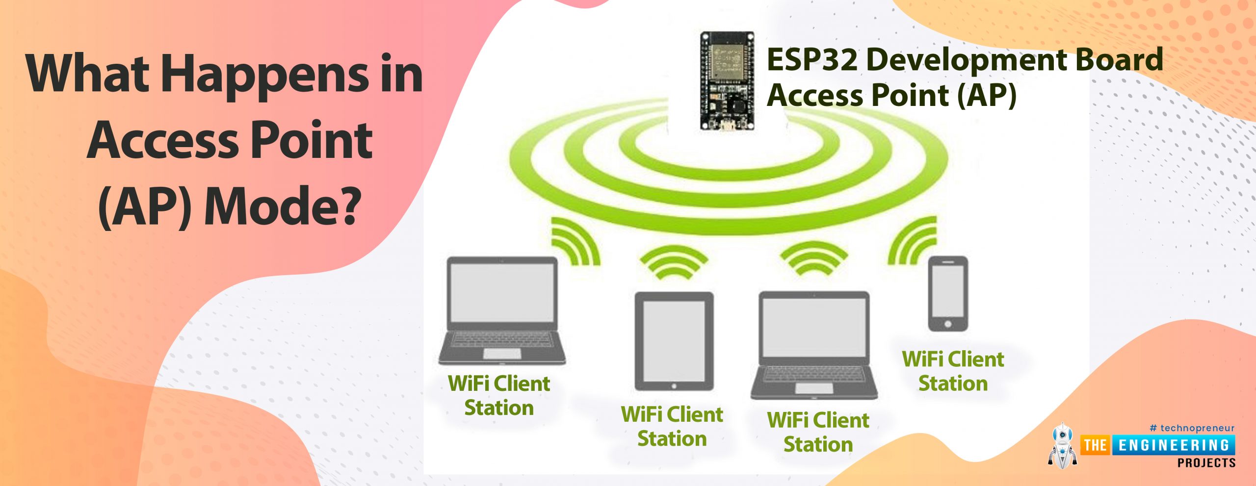
This concludes the tutorial. I hope you found this useful, and I hope to see you soon for the new ESP32 tutorial.ESP32 can be operated as an access point (AP) or a Wi-Fi station (STA mode). So, in this tutorial, we will create an ESP32 web server in access point (AP) mode. Here's the video demonstration of ESP32 WebServer in Access Point Mode:
As I mentioned above, in our 2nd tutorial, we already discussed the basics of the ESP32 web server. So, in this tutorial, we will only discuss how to create the ESP32 in access point mode.
For detailed information about the basics of the ESP32 web server and how client-server communication takes place, follow our previous tutorial (i.e., Create a Web Server with ESP32).
| Where To Buy? | ||||
|---|---|---|---|---|
| No. | Components | Distributor | Link To Buy | |
| 1 | ESP32 | Amazon | Buy Now | |
In Access Point Mode the ESP32 creates its own wireless Wi-Fi network in this mode, similar to the one provided by your existing router. In access point mode, we don't need to connect the ESP2 to a Wi-Fi network. In the Wi-Fi network it creates, the ESP32 Wi-Fi board can connect up to 5 devices.
Fig 1 ESP32 as an Access Point
So, in access point mode, nearby Wi-Fi devices such as mobile phones, laptops, or a secondary ESP32 module acting as a station can connect directly to the AP (ESP32 module) without the need for an external Wi-Fi router.
On the other hand, in Station mode, the ESP32 wi-fi module connects to your Wi-Fi network through a router. The router acts as a conduit for communication between the web client and the ESP32. The Wi-Fi router provides the IP address. This IP address can be used by web clients to connect to the Web server on a local network.
To know about how to set up/operate Arduino IDE for ESP32 compilation, follow our first tutorial i.e., Introduction to ESP32 programming series.
Here we are using an inbuilt example from Arduino IDE(ESP32). You can modify the example code as per your requirements or can write your own code.
A screenshot is attached below to help you find the example code in Arduino IDE.
Fig 2 Wi-Fi access point example
The first task while writing the WiFi code is to add the required wifi header files or libraries in the code.
Here we are adding three libraries.
Fig 3: Libraries
Define the LED pin or a GPIO (for peripheral interface) which we going to control through web server. Here we are using the inbuilt LED which is internally connected with GPIO2
Give a name (SSID) to the ESP32 Access Point and set the password for security purpose ( if you wish to).
While creating a web server we also need to assign a port and usually port 80 is used for local web server.
Inside the setup function, the LED pin is initialized as an output one and then initialized the serial monitor with a baud rate of 115200.
The next task is to configure the ESP32 Wi-Fi module in access point mode. For that, here we are calling a function called WiFi.softAP. Where we are passing two parameters, ssid and password, respectively.
After configuring the AP mode, we need to fetch the IP address of the access point by calling the WiFi.softAPIP() function and printing it on the serial monitor.
Then, after fetching the IP address, we will start the server using the server. perform.
After configuring the Access Point mode and initializing the server, the server will next wait for the station or client connection, which can be a mobile phone, a laptop, or another ESP32 board configured in STA mode.
Once the connection is established between the access point and the client device, the access point will wait for the data input.
A string type variable called currentLine has been defined to hold the incoming data from the client.
If there is a byte to be read from the client, then it will be stored inside the char type variable c.
HTTP header always starts with a response code e.g.: HTTP/1.1 200 ok
An HTML page will be created on the client’s browser, from where the client device can control (ON/OFF) the LED.
Different URLs will be created to turn ON and OFF the LED depending upon the HTML input received from the client device i.e., H (to turn ON the LED) and L ( to turn OFF the LED).
Client.stop() function is responsible for closing the connection between Access Point and client or station device.
Note: If you need any guidance regarding how to upload or compile a code for the ESP32 module in Arduino IDE, follow our first tutorial on the ESP32 programming series.
Here we are going to control the ESP32’s inbuilt LED through an ESP32 web server (AP mode).
We will connect our station or client device through Wi-Fi to the ESP32 module, which (ESP32) is currently acting as an access point (AP).
To establish the connection go to your mobile phone’s Wi-Fi setting.
The Access Point is advertising itself with a pre-defined SSID so that the station devices or clients can find the AP device and can communicate with each other.
If you find a wi-fi device (AP) named ESP32_AP (or as per your SSID) connect to that after entering the assigned password.
Fig. Connected with ESP32 AP
As we are using the inbuilt LED, no external components are required.
After connecting to the access point, you can find the IP address of the AP device printed on the Serial Monitor. As shown in the image below:
Fig.: Serial Monitor
Enter the IP address in the browser. Now you can turn the LED ON or OFF using the web page as shown in the images below.
A web page with URL 192.168.4.1/H will be displayed on the browser when LED is turned ON
Fig.: URL when LED is turned ON
LED is blue color represents the inbuilt LED which is connected to GPIO_2.
Fig.: ESP32 LED ON
Another web page with URL 192.168.4.1/L will be created when the AP will receive the input to turn OFF the inbuilt LED. As shown in the image below:
Fig.: Web page displaying the LED off state.
This concludes today’s tutorial. We hope you find it helpful.
In our next tutorial, we will discuss another ESP32 feature that is BLE (Bluetooth low energy).