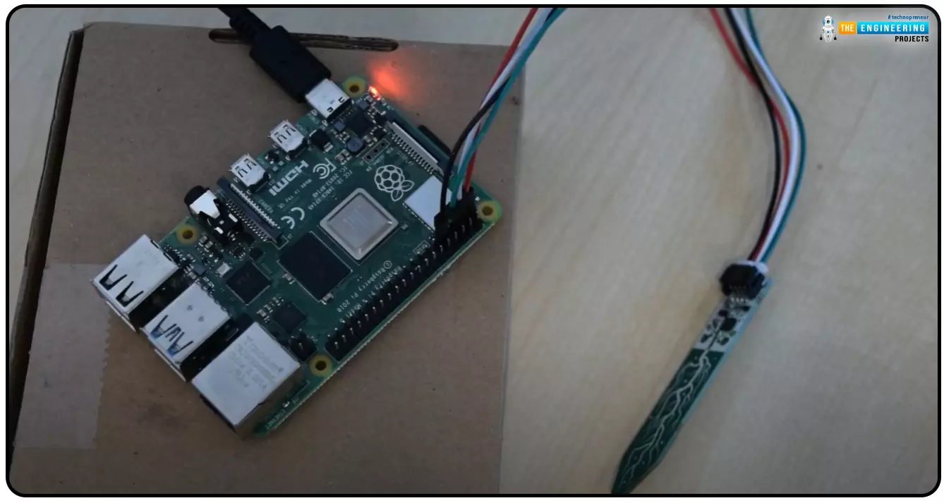
Hello everyone, I hope you all are doing great. Today, we are going to share the second chapter of Section-III in our Raspberry Pi programming course. The previous guide covered how to interface an LDR Sensor with Raspberry Pi 4. This tutorial will cover the basics of hooking up a soil humidity sensor to a Raspberry Pi 4 to get accurate readings. Next, we'll write a Python script to collect the data from the sensors and display it on a Serial monitor.
Are you aware that you can utilize a Raspberry Pi 4 to track the water absorbed by the soil around your houseplants or garden? This helpful guide will show you how to install a soil humidity sensor that will send you a text message when your plant needs watering. A Pi 4, a soil humidity sensor, and a few low-priced components are required. All right, let's get going!
Today, we are going to interface Soil Moisture with Raspberry Pi 4. We will design a simple irrigation system, where we will measure the moisture of the soil and depending on its value, will turn ON or OFF the water pump. We will also use a 20x4 LCD to display values/instructions.
One way to assess soil conditions is with a soil moisture sensor. The electromagnetic signal that the sensor emits travels through the soil. The sensor then evaluates the moisture level based on the signal's reception.
We can use soil moisture sensor has numerous purposes. Saving water is one of them. Adjustments to the watering system can be made based on readings from the sensor that measures the soil's moisture level. This could cut down on both water consumption and waste. Plant health can be enhanced by employing a soil moisture monitor, another perk. We can use this sensor to set off a relay to begin watering the plant if the soil moisture level drops off a given threshold.
The two exposed wires on the fork-shaped probe function as a variable resistor whose resistance changes with the soil's moisture level.
The above figure demonstrates how to use a soil moisture sensor to detect moisture levels. When water is poured into the soil, the voltage of the sensor immediately reduces from 5V to 0V. The module has a potentiometer(blue) that adjusts how sensitively the digital pin changes state from low to high when water is introduced into the soil.
There are typically two components that make up a soil moisture sensor.
Two exposed conductors on a fork-shaped probe are put wherever moisture levels need to be determined. As was previously mentioned, its a variable resistor whose resistance changes as a function of soil moisture.
The sensor also has an electronic module that is interfaced with the microcontroller. The module produces a voltage proportional to the probe's resistance and makes it available through an Analog Output pin. The same signal is then sent to a Digital Output pin on an LM393 High Accuracy Comparator.
The module features a potentiometer (DO) for the fine-tuning of digital output sensitivity. It can be used to establish a threshold i.e. at which threshold the module will output a LOW signal and a HIGH otherwise.
In addition to the IC, the module has two LEDs. When the component is activated, the Power LED will light up, and the Condition LED will light up if the moisture level is above the setpoint.
Four pins are included on the FC-28 soil moisture sensor.
Among the various uses of Moisture Sensors, I am sharing a few here:
As with most things involving the Raspberry Pi, connecting a soil humidity sensor is child's play. we need to connect the soil moisture sensor with Pi 4 GPIO header. This connection requires three wires.
We can now start coding our project because all the pieces are in place. Now is the time to begin.
Here's our hardware setup having soil Moisture Sensor with RPi4:
Here's the Pin's Mapping:
VCC -> 5V
GND -> GND
DATA-> GPIO4
After the sensor has been hooked up, testing it requires the creation of some code. The following code can be copied and pasted into a text editor, then saved as a .py file.
import RPi.GPIO as GPIO
import time
#GPIO SETUP
channel = 4
GPIO.setmode(GPIO.BCM)
GPIO.setup(channel, GPIO.IN)
def callback(channel):
if GPIO.input(channel):
print ("Water Detected!")
else:
print ("Water Detected!")
GPIO.add_event_detect(channel, GPIO.BOTH, bouncetime=300)
GPIO.add_event_callback(channel, callback)
while True:
time.sleep(0)
The below output should be observed if the sensor is operating correctly:
So, there's been a moisture detection! You can change the code to perform any action you like. Once the humidity level is detected, you could activate a motorized or audible alarm, for instance. In the next tutorial, we will Interface a Sharp IR Sensor with RPi4. Stay tuned. Have a good day.
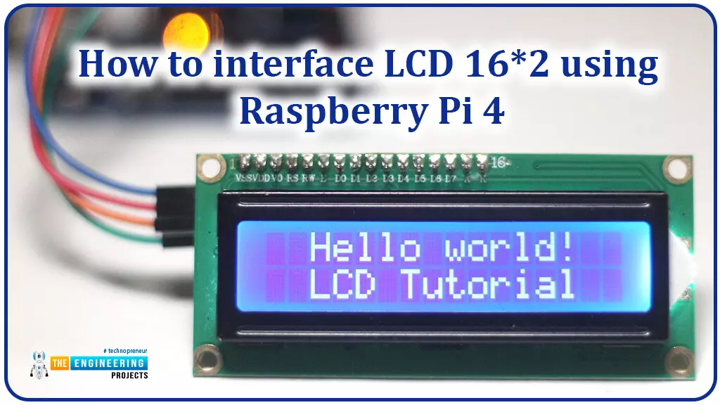
Hello friends, I hope you all are doing great. Today, I am going to share the 6th lecture in the Raspberry Pi 4 Programming series. We're glad you could join us for another lesson in our comprehensive Raspberry Pi programming guide. In today's guide, I'll show you how to interface a 16x2 LCD screen with Raspberry Pi 4.
So, let's get started:
Today, we are going to interface a 16x2 LCD screen with Raspberry Pi 4. At first, we will print the "Hello World" text on the LCD, and in the last section, we will implement the scrolling and blinking of text on the LCD.
We will need the following components for today's project:
The header pins of 16x2 monitors are not pre-soldered. Normally a male header pin is soldered to the LCD pin holes.
We can perform 2 types of communication modes in LCDs, named:
In 8-Bit mode, all 8 data pins are used to send data, while in 4-Bit mode, the last 4 pins(D4-D7) are used for data transmission.
LCDs employ two distinct registers:
You can use the RS pin on LCD to alter the register. If RS is High, we are accessing the data register and if it's Low, we are accessing the command register.
The LCD's command register keeps track of the user's command. Pre-display data is saved in the data register. In order to manipulate the display, one must first load the instruction register with commands and then load the data registers to display the data. If you're working on a Raspberry Pi project and want to avoid learning low-level commands, you can use the Liquid Crystal Library instead.
The screen's brightness can be adjusted from Pin 3, normally a potentiometer is placed at Pin 3 to adjust the brightness. You can also use a resistor if you don't have a potentiometer. If a resistor is used, try one between 5k-10k ohms. You should experiment with a few different values to get the optimal resistance.
LCD works on the principle of light transmission from one layer to the next via molecules. These units vibrate and align themselves in a way that the polarized sheet gets at an angle of 90 degrees, allowing light to pass through. In other words, these molecules inspect the information on every pixel. Every single pixel uses the light absorption technique to display the digits. It is necessary to adjust the molecular orientation to the incident light angle in order to show the value.
The 16x2 LCD screen can easily be connected to the Raspberry Pi 4. There will be a lot of cables to connect because LCD has 16 pins, but nothing too complicated. Here's the schematic of the pin connections between RPi4 and LCD:
Having done so, the screen should power up and establish a connection with the RPi.
The newest Raspbian release has all the necessary packages loaded out of the box to allow for GPIO communication. But we need to install the Liquid Crystal Library to work on the LCD. Let's do that:
git clone https://github.com/pimylifeup/Adafruit_Python_CharLCD.git
cd ./Adafruit_Python_CharLCD
sudo python setup.py install
After the installation, you can use the Adafruit library from any Python program on the Pi. Just paste this line into the beginning of your Python file to make use of the library.
import Adafruit_CharLCD as LCD
The Adafruit LCD library makes it simple to display data from Raspberry Pi to LCD screen. The library package also has several working examples of utilizing the LCD. Before running any of these examples, make sure the pin parameters at the top of the program reflect your setup. My Circuit should yield the following results.
lcd_rs = 25
lcd_en = 24
lcd_d4 = 23
lcd_d5 = 17
lcd_d6 = 18
lcd_d7 = 22
lcd_backlight = 4
lcd_columns = 16
lcd_rows = 2
cd ~/Adafruit_Python_CharLCD/examples/
sudo nano char_lcd.py
Change the values in this section to match the ones described above for the pin configuration. To save the code, hit CTRL+X+Y on your keyboard. To execute this code, open a terminal and type Python followed by the name of the file (including the extension).
python char_lcd.py
In this session, I'll go over the fundamental Python methods for interacting with the screen. To initialize the pins, it is necessary to invoke the following class. Before calling the class, make sure all the parameters have been defined.
lcd = LCD.Adafruit_CharLCD(lcd_rs, lcd_en, lcd_d4, lcd_d5, lcd_d6, lcd_d7, lcd_columns, lcd_rows, lcd_backlight)
After that, you can adjust the screen to your liking. In this short guide, I'll give you a taste of what you can do with the Adafruit library.
The Ardafruit CharLCD.py file in the Adafruit CharLCD folder of the Adafruit Python CharLCD folder will list all the accessible methods.
sudo nano ~/Adafruit_Python_CharLCD/Adafruit_CharLCD/Ardafruit_CharLCD.py
My simple script for displaying user-entered text is included below.
#!/usr/bin/python
# Example using a character LCD connected to a Raspberry Pi
import time
import Adafruit_CharLCD as LCD
# Raspberry Pi pin setup
lcd_rs = 25
lcd_en = 24
lcd_d4 = 23
lcd_d5 = 17
lcd_d6 = 18
lcd_d7 = 22
lcd_backlight = 2
# Define LCD column and row size for 16x2 LCD.
lcd_columns = 16
lcd_rows = 2
lcd = LCD.Adafruit_CharLCD(lcd_rs, lcd_en, lcd_d4, lcd_d5, lcd_d6, lcd_d7, lcd_columns, lcd_rows, lcd_backlight)
lcd.message('Hello\nworld!')
# Wait 5 seconds
time.sleep(5.0)
LCD.clear()
text = raw_input("Type your name in the terminal ")
LCD.message(text)
# Wait 5 seconds
time.sleep(5.0)
LCD.clear()
lcd.message('Goodbye\nWorld!')
time.sleep(5.0)
LCD.clear()
If everything's fine, you will get something printed on your screen, as shown in the below figure:
If your Python script isn't producing any output on the screen, it's probably due to incorrectly configured pins.
This guide walked you through connecting the Pi 4 to a 16x2 LCD. You can accomplish so much more with this sleek screen. You may set up a script to run at boot time and show useful information like the IP address, time, temperature, and more.
You can also incorporate a wide variety of interesting sensors with this screen. A temperature sensor like the DS18B20 would be ideally suited for use with the screen. Refresh the screen every few seconds to reflect the current temperature.
Please let me know how successful you were in putting up a Pi 4 with LCD 16x2 display with the help of this tutorial. In the next tutorial, we will interface Keypad 4x4 with Raspberry Pi 4. Till then, take care. Have fun !!!
We're glad you could join us for another lesson in our comprehensive Raspberry Pi programming guide. I will show you how to install and connect the RFID card chip to your Raspberry Pi through step-by-step instructions.
Modern security systems would only be complete using radio frequency (RFID) devices. To control who can enter a facility or which rooms they can access, RFID chips and card readers are employed. The RFID card's unique identification number can be read wirelessly with a wall-mounted RFID reader. A door will only unlock and allow entry if the RFID card's unique identification number matches a list of approved cards.
It's fun to tinker with this circuit, and it may be used in many other applications, from opening locks to taking attendance. The MFRC522 microcontroller underpins the RFID RC522, a cheap RFID (Radio-frequency identification) reader/writer. The RFID tags can connect with this microcontroller using an electromagnetic field it generates at 13.56MHz and sends to them via the SPI protocol. If you want to use your RFID RC522 with tags, you must ensure that they are 13.56MHz compatible. We'll walk you through the wiring of the RC522 and the creation of Python programs to communicate with the chip, allowing you to read and write RFID tags. Adding a 16x2 LCD to the Raspberry Pi is a simple extension of this tutorial, and it can be helpful if you need to show the user some information or provide a visual prompt.
Where To Buy? | ||||
---|---|---|---|---|
No. | Components | Distributor | Link To Buy | |
1 | Breadboard | Amazon | Buy Now | |
2 | Jumper Wires | Amazon | Buy Now | |
3 | Raspberry Pi 4 | Amazon | Buy Now |
Raspberry Pi
Micro SD Card
Power Supply
RC522 RFID Reader
Breadboard
Breadboard Wire
An RFID reader reads the tag's data when a Rfid card is attached to a specific object. An RFID tag communicates with a reader via radio waves.
In theory, RFID is comparable to bar codes because it uses radio frequency identification. While a reader's line of sight to the RFID tag is preferable, it is not required to be directly scanned by the reader. You can only read an RFID tag up to three feet away from the reader. The RFID tech quickly scans many objects, making it possible to identify a specific product rapidly and effortlessly, even if it is sandwiched between several other things.
Major components of Cards and tags include an integrated circuit (IC) that stores the unique identification value and a copper that acts as the antenna.
Inside the Rfid reader is another copper wire coil. This coil produces a magnetic field when current flows through it. Magnetic flux creates a current inside the wire coil when the card is brought close to the reader. This current can power the card's internal integrated circuit. The reader then takes in the card's serial number. A card reader will send the card's serial number to a central processing unit (CPU) like a Raspberry Pi for further processing.
When you buy an RFID RC522 Reader, you may discover that 90% of them do not have the header pins pre-installed. Due to a lack of pins, you'll have to solder them yourself; however, this is a relatively easy task, even for amateurs. Assuming the header pins that came with your RC522 are too large, you may snap them in half to reduce them to a single column of eight.
Start by inserting the header pins into the RC522 from the top. The circuit may be easily placed on top of the connector pins by inserting the large side of the pins onto a breadboard. The breadboard's secure holding of the pins will make soldering them to the RFID circuit much simpler.
Solder each pin individually by carefully heating your soldering iron and applying it to the pins. Remember that heating the junction slightly before to solder application increases the solder's adhesion and decreases the likelihood of generating a cold joint. When using solder, we advise you to be conservative. When you've finished soldering the header pins onto your RFID circuit, you'll be ready to move on with the guide.
There are eight different connectors on the RFID RC522. Except for the IRQ, we need to connect all these to the GPIO pins on our Raspberry Pi.
This guide shows how to connect an RFID RC522 to a Breadboard and then to the Raspberry Pi's GPIO Pins, although you could also wire the components straight to the Pi.
Simply connecting 7 of the Raspberry Pi's GPIO pins to the RFID RC522 reader is all needed to get it up and to run. Refer to the GPIO pin locations detailed in our tutorial and the table below when deciding how to wire your RC522.
SDA connects to Pin 24.
SCK connects to Pin 23.
MOSI connects to Pin 19.
MISO connects to Pin 21.
GND connects to Pin 6.
RST connects to Pin 22.
3.3v connects to Pin 1.
We need to adjust the Raspberry Pi's settings before we can use the RFID RC522. Inconveniently, our RFID reader circuit relies on the Raspberry Pi's SPI (Serial Peripheral Interface), which is disabled by default. Worry not, though, as it is easy to restore this interface; follow our instructions below to set up your RPi and Raspbian to use the SPI port. Launch the raspi-config utility by opening a terminal and typing the following command.
sudo raspi-config
A menu of choices will appear when you use this tool. You may read up on all of these options in the raspi-config documentation. Choose "5 Interfacing Options" using the arrow keys. Select this choice, and then hit the Enter key. Once "P4 SPI" is selected in the next screen, press Enter once more to confirm your selection. To continue, use the arrow keys to choose "Yes" and then press Enter when prompted to confirm that you want to activate the SPI Interface. For the raspi-config utility to finish enabling SPI, you'll have to be patient for a while.
The raspi-config tool's success in enabling the SPI interface will be shown by the display of the message "The SPI interface is enabled." Activating the SPI Interface requires a full reboot of the Raspberry Pi. Press Enter, and then ESC, to return to the terminal. If you want to restart the RPi, enter the following Unix instruction into the terminal.
sudo reboot
It is time to verify that Raspberry Pi has been activated now that it has rebooted. Checking if spi bcm2835 is available is as simple as running the following command.
lsmod | grep spi
If you get spi bcm2835, you're good to go with the rest of the tutorial. If you tried the preceding command and it didn't work, try the following three things. If the SPI component is not enabled, we can manually modify the boot config file by issuing the following code to our RPi.
sudo nano /boot/config.txt
You can use CTRL + W to search the configuration file for "dtparam=spi=on" If you think you have discovered it, look if it has a number in front of it. If there is, delete it because it disables the code. If you cannot find the line, add "dtparam=spi=on" to the very end of the file. To commit your modifications, use CTRL + X, followed by Y and Enter. You can double-check that the module has been activated by restarting your Raspberry Pi, as in Step 5.
After connecting our RFID circuit to the RPi, we can turn it on and start writing Python scripts to communicate with the chip. You'll learn how to read and write information to RFID chips by composing scripts like the ones we'll provide. These will serve as the foundation for future RFID RC522 tutorials and provide you with a fundamental understanding of how data is handled. The Raspberry Pi must be brought up to date with the most recent software versions before we can begin programming. Get the latest version of Raspbian for your Pi by running these two commands.
sudo apt update
sudo apt upgrade
Installing the python3-dev, python-pip, and git packages is the last thing to do before moving forward. To get your RFID reader set up with this guide, type the following command into your Raspberry Pi's terminal.
sudo apt install python3-dev python3-pip
Now that we have python "pip" installed on our Raspberry Pi, we can install the spidev Python library. An integral part of this guide, the spidev library allows the RPi to communicate with the RFID via the SPI. Run the following command to get spidev set up on your Raspberry Pi via pip. It's important to remember that we're using sudo to guarantee that the package gets installed for everyone's usage, not just the logged-in user.
sudo pip3 install spidev
After getting the spidev library up and running on our Raspberry Pi, we'll move on to setting up the MFRC522 library with pip. Two files, in particular, are used by us, both of which are part of the MFRC522 library:
This library, MFRC522.py, implements the RC522 interface for communicating with RFIDs via Raspberry Pi's SPI port.
Simplifying the MFRC522.py file so that you only need to work with a small subset of its many functions, SimpleMFRC522.py is a significant time saver.
Enter this command into your terminal to have pip setup the MFRC522 library on your Pi 4:
sudo pip3 install mfrc522
Now that the library has been transferred to the Pi, we can start writing code for the RFID RC522. First, we'll explore how to use the RC522 to program your RFID cards. Move on to the following part, where we will write our first Python code.
In this first Python script, we'll go over the steps needed to send information from the RC522 to RFID tags. This is made more accessible by the SimpleMFRC522 script, but we'll still break down the code's individual components for you. To begin, let's create a directory to hold the scripts we'll be using. Create the "pi-RFID" folder by using the following command.
mkdir ~/pi-rfid
To get started, navigate to the folder you just cloned and create the Write.py script in Python.
cd ~/pi-RFID
sudo nano Write.py
Add the following blocks of code to this file. This code prompts you for some text, which it then uses to update the RFID Tag.
#!/usr/bin/env python
import RPi.GPIO as GPIO
from mfrc522 import SimpleMFRC522
The very first line of the code snippet instructs the terminal to use Python rather than another scripting language like Bash to parse and run the file. To guarantee that the GPIO Pins are reset when the script terminates, we must first import the RPi.GPIO package contains all the necessary functions for communicating with the GPIO Pins. The second import is our SimpleMFRC522 library, which will be used to communicate with the RFID RC522. Compared to the standard MFRC522 library, it dramatically simplifies working with the chip.
reader = SimpleMFRC522()
In this line, we make a new instance of the SimpleMFRC522 object, use its setup function, and save the result in our readers variable.
try:
text = input('New data:')
print("Now place your tag to write")
reader.write(text)
print("Written")
We enclose the following section of code with a try statement to ensure that any unforeseen problems are handled, and the code is cleaned up correctly. Python is whitespace sensitive; it uses tabs to distinguish between code sections, so keep them after trying. In this case, the second line reads a command-line input and stores it in a text variable using Python 3's input function.
The third line makes advantage of print() to prompt the user to set the RFID tag onto the reader. After that, on line 4, we utilize our scanner object to instruct the RFID Circuit to write the text field's contents to a certain sector of the RFID tag. On line 5, after successfully writing to the RFID tag, we call print() once more to inform the user.
finally:
GPIO.cleanup()
The script will terminate in the last two lines of code. The finally statement always follows the try statement. Thus the GPIO.cleanup() method is called after each iteration of the try block. These lines are essential because improper cleanup can disrupt the functionality of other programs. Upon completion, your script should be like the example given below.
The file can be saved by pressing CTRL Plus X, Y, then ENTER once you've double-checked the code and are convinced it's correct. Now that the script is written, we need to put it through some testing. Get an RFID tag ready before running the script for testing. When you're ready, open the terminal on your Raspberry Pi and enter the following command.
sudo python3 Write.py
In this situation, we're just going to type in "any word" because it's easy to remember and short. Press the Enter key when you have finished writing and are ready to send. After that, your RFID Tag can be placed directly above your RFID circuit. It will immediately update the tag with fresh information when it does. You'd see the word "Written" on the command prompt if it worked. Now that you have your Write.py script completed, we can move on to explaining how to read information from the RFID RC522.
We have successfully programmed our RC522 to print to RFID tags and can now move on to writing a script to retrieve the data from the tags. First, we'll make sure we're in the correct location by switching directories, and then we'll use nano to start drafting the Read.py script.
cd ~/pi-rfid
sudo nano Read.py
Incorporate the following code into this document. When an RFID tag is placed in the RFID reader, the script will wait until the tag's data has been read before displaying the results.
This file's first line of code instructs the operating system on how to proceed when the user clicks the "Run" button. If you don't specify that it's a Python file, it'll try to run it like any other script. An initial RPi.GPIO import is made. Importing this library ensures that the Raspberry Pi's GPIO pins are cleaned up after script termination, as it contains all the necessary functions. SimpleMFRC522 is the second import. With the assistance functions included in this script, reading and writing to an RFID RC522 is a breeze, whereas, with them, the scripts would quickly grow to be manageable.
This line is crucial because it invokes SimpleMFRC522's creation method, which returns an object that is subsequently stored in our reader variable.
try:
id, text = reader.read()
print(id)
print(text)
The following code section will be encapsulated in a try block to allow us to handle any unforeseen errors gracefully. Because Python is sensitive to whitespace, you must use the 'tabs' as displayed following try:
In this scenario, the second line of this code block initiates a call on our scanner object, instructing the circuits to begin scanning any Rfid card that is positioned on top of the reader. On the third and forth lines, we use print() to display the data we gleaned from the RFID Chip; this includes the tag's unique identifier and any text it may consist of.
finally:
GPIO.cleanup()
The script ends with the last two lines of code. No of what happens inside the try block, the final statement is always executed afterward. No matter what, the GPIO.cleanup() code will be executed thanks to this try statement. It's vitally important, as not doing so can disrupt the proper operation of other scripts that rely on the GPIO. Your completed Read.py script for the RFID RC522 should resemble the example below.
When you've double-checked your code and are satisfied with it, press Ctrl + X, then Y, and finally ENTER to save the file. The time has come to put our completed Read.py script to the test. Get ready to test the script by picking up any of the RFID tags. If you're all set, enter this command into the terminal on your Raspberry Pi.
sudo python3 Read.py
Now that the script is active, you can set your RFID Tag atop your RFID circuit. When the RFID tag is placed on top, the Python program will immediately begin reading the information from the tag and display the results on the screen. What a finished product might look like is shown below as an illustration.
To test whether your Raspberry Pi is properly connected on the RFID RC522 Circuit, run the Read.py script and see if it returns any data that matches the text you wrote to the card in the Write.py script.
Connecting an RC522 RFID module to a Pi 4 makes reading MIFARE chips and cards is now possible. This might be very useful in security systems and other applications where identifying an item or person is required without the user having to physically interact with the device by pressing buttons, switching, or activating any sensors. Eventually, you should be able to use this to decipher the UID encoded on your MIFARE tags. You should know that these cards can be duplicated and assigned a new unique identifier (UID) if you plan on employing this technique in a security system. To ensure the safety of your system, you must ensure that no one learns your UID or gains remote access to your devices. The contactless tags are convenient because they can be attached to a keychain, and the cards are convenient because they can be carried in a wallet. Both things can be concealed inside others to give them a hidden identifier that the Pi can access. With the help of our Pi 4-powered RFID attendance systems guide, you can learn how to set up your RFID Reader/Writer for use in checking attendance. Our exploration of the RFID chip and the scripts above will continue in subsequent guides. A door security system is one of the fantastic DIY Pi ideas we'll look into. The next lesson will teach you how to connect a 16x2 LCD screen to a Raspberry Pi 4.
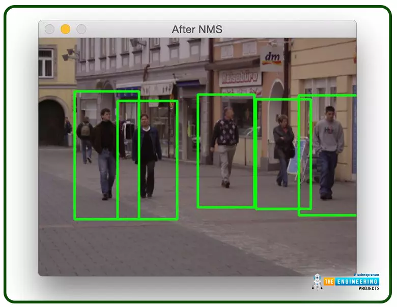
Greetings, and welcome to today's tutorial. In the last tutorial, we learned how to construct a system for tallying individuals using Raspberry Pi, astute subtraction, and blob tracking. We demonstrated the total number of building entrances and exits. Feature computation and HOG theory were also discussed. The tests proved that a device based on the raspberry pi could effectively function as a people counting station. One of the many benefits of the Pi 4 is its internet connectivity, which is especially useful for home automation projects due to its low price and ease of use. We're going to see if we can use a web page's buttons to manage our air conditioner today. With this Internet of Things (IoT) based home automation, you can command your home gadgets from the comfort of your couch. The user can access this web server from any gadget capable of loading HTML apps, such as a smartphone, tablet, computer, etc.
Where To Buy? | ||||
---|---|---|---|---|
No. | Components | Distributor | Link To Buy | |
1 | Breadboard | Amazon | Buy Now | |
2 | Diodes | Amazon | Buy Now | |
3 | Jumper Wires | Amazon | Buy Now | |
4 | LEDs | Amazon | Buy Now | |
5 | Resistor | Amazon | Buy Now | |
6 | Transistor | Amazon | Buy Now | |
7 | Raspberry Pi 4 | Amazon | Buy Now |
The needs of this project can be broken down into two broad classes: hardware and software.
Raspberry Pi 4
Memory card 8 or 16GB running Raspbian Jessie
5v Relays
2n222 transistors
Diodes
Jumper Wires
Connection Blocks
LEDs to test.
AC lamp to Test
Breadboard and jumper cables
220 or 100 ohms resistor
We'll be using the WebIOPi framework, notepad++ on your PC, and FileZilla to transfer files (particularly web app files) from your computer to the raspberry pi and the Raspbian operating system.
As a good habit, I constantly update the Raspberry Pi before using it for the first time. In this project phase, we will handle the web-to-raspberry-pi connection by upgrading the Pi and setting up the WebIOPi framework. The python Flask framework provides a potentially more straightforward alternative, but getting your hands dirty and looking at how things operate makes DIY appealing. When you get to that point, the fun of DIY begins. Use the updated commands below to upgrade your Raspberry Pi and restart the RPi.
sudo apt-get update
sudo apt-get upgrade
sudo reboot
After this is finished, we can set up the webIOPi framework. Using, verify that you are in your home directory.
cd ~
To download the files from the google page, type wget.
wget http://sourceforge.net/projects/webiopi/files/WebIOPi-0.7.1.tar.gz
Then, once the download is complete, unzip the file and enter the directory;
tar xvzf WebIOPi-0.7.1.tar.gz
cd WebIOPi-0.7.1/
Unfortunately, I could not locate a version of WebIOPi that is compatible with the Pi 4; thus, we have to download a patch before proceeding with the setup. Run the instructions below from within the WebIOPi directory to apply the patch.
wget https://raw.githubusercontent.com/doublebind/raspi/master/webiopi-pi2bplus.patch
patch -p1 -i webiopi-pi2bplus.patch
Once we have those things, we can begin the WebIOPi setup installation process by using the;
sudo ./setup.sh
Just click "Yes" when prompted to install more components during setup. Upon completion, restart your Pi.
sudo reboot
Before diving into the schematics and programs, we should power on the Raspberry Pi and ensure our WebIOPi installation is functioning as expected. Execute the command below;
sudo webiopi -d -c /etc/webiopi/config
After running the above command on the pi, open a web browser and navigate to http://raspberrypi.mshome.net:8000 (or HTTP;//thepi'sIPaddress:8000) on the computer that is attached to the pi. When logging in, you'll be asked for a username and password.
Username is webiopi
Password is raspberry
You may permanently disable this login if you no longer need it. Still, it's important to keep unauthorized users from taking control of your home's appliances and Internet of Things (IoT) components. After you've logged in, go to the GPIO header link.
Make GPIO 17 an output; we'll use it to power an LED in this Test.
Following this, attach the led to the Pi 4 as depicted in the schematics.
When you're ready to activate or deactivate the LED, return to the web page where you made the connection and select the pin 11 button. This allows us to use WebIOPi to manage the Raspberry Pi's GPIO pins. If the Test is successful, we can return to the console and exit the program by pressing CTRL + C. Please let me know in the comments if this arrangement has any problems. Once the pilot is finished, we can begin the actual project.
In this section, we will alter the WebIOPi service's standard setup and inject our code to be executed on demand. FileZilla or another FTP/SCP copy program will be the first tool we install on our computer. You'll agree that using the terminal to write code on the Pi is a stressful experience, so having access to Filezilla or another SCP program will be helpful. Let's make a project directory in which all our web scripts will be stored before we begin writing the HTML, CSS, and javascript programs for this Internet - of - things Home automated Web app and transferring them to the RPi.
First, make sure you're in your home directory using; next, create the folder; finally, open the newly constructed folder and make an HTML folder inside it.
cd ~
mkdir webapp
cd webapp
mkdir HTML
Make subfolders inside the HTML folder for scripts, CSS, and graphics.
mkdir html/css
mkdir html/img
mkdir html/scripts
Now that we have our files prepared, we can start coding on the computer and transfer our work to the Pi using Filezilla.
Writing the javascript will be our first order of business. An easy-to-use script for interacting with the WebIOPi server. Our four-button web app will only use two relays in the demonstration, and we only intend to control four GPIO pins for this project.
webiopi().ready(function() {
webiopi().setFunction(17,"out");
webiopi().setFunction(18,"out");
webiopi().setFunction(22,"out");
webiopi().setFunction(23,"out");
var content, button;
content = $("#content");
button = webiopi().createGPIOButton(17," Relay 1");
content.append(button);
button = webiopi().createGPIOButton(18,"Relay 2");
content.append(button);
button = webiopi().createGPIOButton(22,"Relay 3");
content.append(button);
button = webiopi().createGPIOButton(23,"Relay 4");
content.append(button);
});
Once the WebIOPi is ready, the preceding code is executed. To help you understand JavaScript, we've explained below:
webiopi().ready(function()
All this tells our system to make this function and call it once the webiopi is set.
webiopi().setFunction(23,"out")
We can instruct the WebIOPi program to use GPIO23 for output. Four buttons are now available, but you may add more if necessary.
var content, button
With this line, we're instructing the system to make a new variable called content into a button.
content = $("#content")
We will continue using the content variable in our HTML and CSS. As a result, the WebIOPi framework generates everything connected to #content when it is mentioned.
button = webiopi().createGPIOButton(17,"Relay 1")
WebIOPi can make several distinct types of push buttons. This code instructs the WebIOPi program to generate a GPIO key that operates on the GPIO pin identified as "Relay 1" above. The other ones are the same, too.
content.append(button)
Add this code to the button's existing HTML or external code. New buttons can be made that are identical to this one in every respect. This is especially helpful while coding or writing CSS.
If you made your JS files the same way I did, you can save them and then move them with Filezilla to webapp/HTML/scripts after you've finished making them. Now we can move on to developing the CSS.
With the aid of CSS, our Internet of Things (IoT) Rpi 4 home automation website now looks fantastic. So that the website will look like the one in the picture below, I built a custom style sheet called smarthome.css.
I don't want to paste the entire CSS script here, so I'll use a subset for the explanation. If you want to learn CSS, all you have to do is read the code. You can skip this and use our CSS code if you want to.
The first section of the script, displayed below, represents the web application's main stylesheet.
body {
background-color:#ffffff;
background-image:URL('/img/smart.png');
background-repeat:no-repeat;
background-position:center;
background-size:cover;
font: bold 18px/25px Arial, sans-serif;
color:LightGray;
}
The above code, which I hope needs no explanation, begins by setting the background colour to white (#ffffff), adds a background image to the document from the specified folder (remember the one we created earlier? ), makes sure the picture doesn't duplicate by setting the background-repeat to no-repeat, and finally tells the CSS to center the background. Next, we adjust the background's text size, font, and colour.
After finishing the main content, we styled the buttons with CSS.
button {
display: block;
position: relative;
margin: 10px;
padding: 0 10px;
text-align: center;
text-decoration: none;
width: 130px;
height: 40px;
font: bold 18px/25px Arial, sans-serif; color: black;
text-shadow: 1px 1px 1px rgba(255,255,255, .22);
-WebKit-border-radius: 30px;
-Moz-border-radius: 30px;
border-radius: 30px;
}
Everything else in the script is similarly optimized for readability and brevity. You can play with them and see what happens; this kind of learning is known as "learning by doing," I believe. However, CSS's strengths lie in its simplicity, and its rules are written in plain English. The button's text shadow and button shadow are two of the few supplementary features found in the block's other section. To top it all off, pressing the button triggers a subtle transition effect, making it look polished and lifelike. To guarantee optimal page performance on all browsers, these are defined independently for WebKit, firefox, opera, etc.
The following code snippet notifies the WebIOPi service that it is receiving data as input.
input[type="range"] {
display: block;
width: 160px;
height: 45px;
}
Providing feedback on when a button is pressed will be the last element we want to implement. As a result, the screen's colour scheme and button hues provide a quick indicator of progress. To accomplish this, the following line of code is added to each button's HTML.
#gpio17.LOW {
background-color: Gray;
color: Black;
}
#gpio17.HIGH {
background-color: Red;
color: LightGray;
}
The code snippets up top alter the button's color depending on the user's selection. The button's background is gray when it is inactive (at LOW) and red when it is active (at HIGH). Now that we have our CSS under control let's save it as smarthome.css, upload it to our raspberry pi's styles folder using FileZilla (or another SCP client of your choosing), and fix the remaining HTML code.
The HTML code unifies the style sheets and java scripts.
<!DOCTYPE HTML PUBLIC "-//W3C//DTD HTML 4.01 Transitional//EN" "http://www.w3.org/TR/html4/loose.dtd">
<html>
<head>
<meta http-equiv="Content-Type" content="text/html; charset=UTF-8">
<meta name="mobile-web-app-capable" content="yes">
<meta name="viewport" content = "height = device-height, width = device-width, user-scalable = no" />
<title>Smart Home</title>
<script type="text/javascript" src="/webiopi.js"></script>
<script type="text/javascript" src="/scripts/smarthome.js"></script>
<link rel="stylesheet" type="text/CSS" href="/styles/smarthome.css">
<link rel="shortcut icon" sizes="196x196" href="/img/smart.png" />
</head>
<body>
</br>
</br>
<div id="content" align="center"></div>
</br>
</br>
</br>
<p align="center">Push button; receive bacon</p>
</br>
</br>
</body>
</html>
The head tag contains several crucial elements.
<meta name="mobile-web-app-capable" content="yes">
The code line above makes it possible to add the web app to the mobile device's home screen when using Chrome or Safari. You can access this function using the Chrome menu. This makes it so the app may be quickly launched on any mobile device or desktop computer.
The following line of code provides a measure of responsiveness for the web app. Because of this, it can take up the entire display of any gadget on which it is run.
<meta name="viewport" content = "height = device-height, width = device-width, user-scalable = no" />
The web page's title is defined in the following line of code.
<title>Smart Home</title>
The following four lines of code all connect the Html file to multiple resources it requires to function as intended.
<script type="text/javascript" src="/webiopi.js"></script>
<script type="text/javascript" src="/scripts/smarthome.js"></script>
<link rel="stylesheet" type="text/CSS" href="/styles/smarthome.css">
<link rel="shortcut icon" sizes="196x196" href="/img/smart.png" />
The first line above directly connects to the WebIOPi framework JavaScript, which is stored in the server's root directory. This method must be invoked whenever WebIOPi is used.
The second line tells the HTML document where to find our jQuery script, and the third tells where to get our style sheet. The last line prepares an icon for the mobile desktop, which can be useful if we use the website as an app or a favicon.
To ensure that our HTML code displays whatever is contained in the JavaScript file, we include break tags in the body portion of the code. The definition of our button's content was made previously in the JavaScript code, and its id="content" should bring that to mind.
<div id="content" align="center"></div>
Everybody is familiar with the routine of saving an Html file as index.html and then transferring it to the Pi's HTML folder via Filezilla.
Before we can begin sketching out circuit diagrams and running tests on our web app, we need to make a few adjustments to the webiopi service's configuration file, instructing it to look for configuration information in our HTML folder rather than the default location.
Edit the configuration by executing the following commands as root:
sudo nano /etc/webiopi/config
Find the section of the configuration file labelled "HTTP" and look for the line that begins with "#" Modify the directory where HTML and resources are stored by default with doc-root.
Remove the # comments from anything below it, and if your folder is organized like mine, set the doc-root to the location of your project file.
doc-root = /home/pi/webapp/html
Lastly, save your work and exit. If you already have another server installed on the Pi utilizing port 8000, you may easily change it. If not, let's stop saving and call it a day.
It's worth noting that the WebIOPi service password can be changed using the command;
sudo webiopi-passwd
A new login name and password will be required. Getting rid of this entirely is possible, but safety comes first.
Finally, issue the following command to start the WebIOPi service.
sudo /etc/init.d/webiopi start
If you want to see how the server is doing, you can do so by;
sudo /etc/init.d/webiopi status
That's why there's a way to halt its execution:
sudo /etc/init.d/webiopi stop
Setup WebIOPi to start automatically with;
sudo update-RC.d webiopi defaults
To do the opposite and prevent it from starting up automatically, use the following;
sudo update-RC.d webiopi remove
Now that we have everything set up, we can begin developing the schematics for our Web-controlled home appliance.
Whereas I could not procure relay modules, which in my experience, make electronics projects simpler for do-it-yourselfers. So, I'm going to draw some diagrams for regular, single-relay, 5V-powered standalone devices.
Join the components as seen in the fritzing diagram. It's important to remember that your Relay's COM, NO (usually open), and NC (typically Close) contacts could be on opposite sides. Please verify this with a millimetre.
Relays can be found anywhere that electricity is being switched, from a simple traffic light controller to a high-voltage switchyard. Relays, in the broadest sense, are equivalent to any other switch. They can connect or disconnect a circuit and are frequently employed to activate or deactivate an electrical load. However, this is a comprehensive statement; there are many other relays, and each Relay behaves slightly differently depending on the task at hand; as the electromechanical Relay is one of the most widely used relays, we will devote more space to discussing it here. In spite of variations in design, all relays work according to the same fundamental concept, so let's dive into the nuts and bolts of relays and talk about how they function.
A relay is called an electromechanical switch that may either establish or rupture an electrical connection. A relay is like a mechanical switch, except that it is activated and deactivated by an electronic signal rather than by physically flipping a switch. It comprises a flexible movable mechanical portion controlled electrically through an electromagnet. Once again, this Relay operating concept is suitable exclusively for electromechanical relays.
A common and widely used relay consists of electromagnets typically employed as a switch. However, there are many kinds of relays, each with its purpose. When a signal is received on one side of the device, it controls the switching activity on the other, much like the dictionary definition of Relay. That's right, a relay is an electromechanical switch that can open and close circuits. This device's primary function is to establish or sever contact with the aid of a signal to turn it ON or OFF automatically and without human intervention. Its primary use is to allow a low-power signal to exert control over a circuit with a high power consumption. Typically, the high-voltage circuit is controlled by a direct current (DC) signal.
The following diagram depicts the internal structure and design of a Relay.
A coil of copper wire is wound around a core, which is then placed inside a housing. When the coil is electrified, it attracts the movable armature, which is supported by a spring or stand and has a metal contact attached to one end. This assembly is positioned over the core. In most cases, the movable armature is a shared connection point for the motor's internal components and the other wiring harness. The usually closed (NC) pin is linked to the common terminal, while the ordinarily opened (NO) pin is not used in operation. By connecting the armature to the usually open contact whenever the coil is activated, current can flow uninterruptedly through the armature. When the power is turned off, it returns to its starting position.
The picture below shows a schematic of the Relay's circuit in its most basic form.
In the images below, you can see the main components of an electromechanical relay—an electromagnet, a flexible armature, contacts, a yoke, and a spring/frame/stand. They have been thoughtfully placed into a relay.
The workings of a Relay's mechanical components have been outlined below.
Electromagnet
An electromagnet is crucial to the operation of a relay. This metal lacks magnetic properties but can be transformed into a magnet when exposed to an electrical current. It is healthy knowledge that a conductor takes on the magnetic characteristics of the current flowing through it. Thus, a metal can operate as a magnet and attract magnetic objects within its range when wound with a conductive material and powered by an adequate power source.
Movable Armature
A moveable armature is just one piece of metal that can rotate or stand on its own. It facilitates connection-making and -breaking with the contacts attached to it.
Contacts
Internal conductors are the wires that run through a device and hook up to its terminals.
Yoke
It's a tiny metal piece attached to a core that attracts and retains the armature whenever the coil is activated.
Spring (optional)
While some relays can function without a spring, those that do have one attach it to the armature at one end to prevent any snagging or binding. One can use a metal "stand" in place of a spring.
Let's examine the differences between a relay's normally closed and normally open states.
If no current flows through the core, there will be no magnetic field, and the device will not be a magnet. As a result, it is unable to draw in the flexible framework. So, the ordinarily closed position of the armature is the starting point (NC).
When a high enough voltage is supplied to the core, it begins to have a strong magnetic field around itself, allowing it to function as a magnet. The magnetic field produced by the core attracts the movable armature whenever it comes within its field of influence, changing the armature's location. As it has been wired to a normally open relay pin, any external circuits attached to it will no longer operate in the same way.
It is important to connect the relay pins correctly so that the external circuit can do its job. When a coil is powered, the armature is drawn toward it, revealing the switching action; when the power is cut, the coil loses its magnetic property, and the armature returns to its original location. The animation provided below shows the Relay in action.
There is nothing complicated about a transistor, yet there is a lot going on inside it. Okay, so first, we'll tackle the easy stuff. An electronic transistor is a small component that can switch between two functions. It's a switch that can also act as an amplifier.
An amplifier is a device that takes in a little electric current and outputs a significantly larger electric current (called an output current). It can be thought of as a current booster. One of the earliest applications for transistors, this is particularly helpful in devices like hearing aids. A hearing aid contains a microscopic microphone that converts ambient sound into electrical signals. These are then amplified by a transistor and used to power a miniature loudspeaker, which reproduces the ambient noise at a much higher volume.
It is possible to use a transistor as a switch. A transistor is a device that allows for the passage of one electrical current to induce a much larger current to flow through the next part of the device. What this means is that a relatively small current can activate a much larger one. All computer chips function in this general way. As an illustration, a memory chip may have as many as a billion individually controllable transistors. Due to the fact that each transistor can exist in either of two states, it is capable of storing either a zero or a one. A chip's ability to hold billions of zeroes and ones, as well as almost as many regular numbers and letters, is made possible by its billions of transistors.
Diodes can range in size from what's shown in the image up top. They feature a cylindrical body that is usually black with a stripe at one end and certain leads that protrude so that we may plug it into a circuit. The opposite terminal is called the cathode and is opposite the anode.
A diode is an electrical component that restricts current flow in one direction.
To illustrate, picture a swing valve fitted in a water line. The water pressure inside the pipe will force open the swing gate, allowing the water to flow uninterrupted. In contrast, the gate will be forced shut, and water flow will stop if the river alters its course. As a result, there is only one direction for water to flow.
Very much like a diode, which we also employ to alter the current flow through a circuit, it allows us to switch it on and off at will.
We have now animated this process using electron flow, in which electrons move from negative to positive. However, traditional flow, positive to negative, is the norm in electronics engineering. It's usually best to start with the conventional current because it's more familiar to most people, but feel free to use either one; we'll assume you're aware of the difference.
It's important to remember that the light-emitted diode will only light up properly if the diode is connected to the circuit in the correct orientation when adding it to a simple Light emitted diode circuit like the one shown above. Only one direction of current can travel through it. Accordingly, its conductive or insulating properties are determined by the orientation in which it is mounted.
So that it can conduct electricity, you must join the black end to the neutral and the striped end to the positive. The forward bias is the condition in which current can flow. If we invert the diode, it will become an insulator and stop the passage of electricity. The term for this is "the reverse bias."
You probably know that electricity is the transfer of electrons between atoms that are not bound. Because of its high number of unpaired electrons, copper is widely used for electrical wiring. Since rubber is an insulator—its electrons are kept very securely, so they cannot flow between atoms—it is used to wrap around the copper wires for our protection.
In a simplified form of a metal conducting atom, the nucleus is at the center, and the electrons are housed in a series of shells around it. It takes a specific amount of energy for an electron to be absorbed into each shell, and each shell has a max number of electrons it can hold. Those electrons that are furthest from the nucleus are the most energetic. Conductors have between one and three electrons in their outermost "valence" shell.
The nucleus acts as a magnet, keeping the electrons in place. However, there is yet another layer, the conduction band. If an electron gets here, it can leave its atom and travel to another. Because the valence shell and conduction band of a metal atom overlap, the electron can move quickly and easily between the two.
The insulator has a tightly packed outer layer. No free space for electrons to occupy. Because of the strong attraction between the nucleus and the electrons and the great distance between the nucleus and the conduction band, the electrons are trapped inside the nucleus and cannot leave. Because of this, electricity is unable to travel through it.
Of course, a semiconductor is also a different type of material. A semiconductor might be silicon, for instance. This material behaves as an insulator because it has one more electron than is necessary in its outermost shell to be a conductor. However, with enough external energy, a few valence electrons can generate enough momentum to hop across to the conduction band, where they can finally break free. Consequently, this substance can perform the roles of both an insulator and a conductor.
Due to the lack of free electrons in pure silicon, engineers must add a small number of materials (called "doping") to the silicon to alter its electrical properties.
This process gives rise to P-type and N-type doping, respectively. The diode itself is a combination of these doped materials.
Two leads connect the anode and cathode to various thin plates inside the diode. P-Type doped silicon is on the anode side of these plates, and the cathode side is N-Type doped silicon—an insulating and protective resin that coats the entire structure.
Consider the material to be pure silicon before it has been doped. There are four silicon atoms surrounding each one. Because silicon atoms need eight electrons to fill their valence shells but only have four available, they share one with their neighbours. Covalent bonding describes this type of interaction.
Phosphorus, an N-type element, can be substituted for a number of silicon atoms in a compound semiconductor. Phosphorus has a 5-electron valence shell because of this. This extra electron isn't needed because particles are sharing them to reach the magic number of 8. This means there's an extra electrons in the material, and it's free to go wherever it wants.
In P-type doping, a substance like aluminum is introduced. Due to its limited valence electron pool of 3, this atom is unable to share an electron with any of its four neighbours. An electron-sized void is therefore made available.
We now have silicon with either too many or too few electrons, depending on the doping method.
Upon joining, the two substances forge a p-n junction. This is a depletion region, and it forms at the intersection. Here, some of the surplus electrons on the N-type side migrate over to fill the vacancies on the P-type side. By moving in this direction, electrons and holes will accumulate on either side of a barrier. Holes are thought to be positively charged since they are the opposite of electrons, which are negatively charged. The resulting accumulation produces two distinct regions, one slightly negatively charged and the other slightly positively charged. This forms an electric field that blocks the path of any more electrons. In regular diodes, the voltage drop over this area is only 0.7V.
By applying a voltage across the diode with the P-Type anode linked to the positive and the N-Type cathode attached to the negative, a forward bias is established, and current can flow. The electrons can't get over the 0.7V barrier unless the voltage source is higher.
We can achieve this by connecting the positive terminal of the power supply to the cathode of an N-type device and the negative terminal to the anode of a P-type device. The diode functions as a conductor to block current because the barrier expands as holes are drawn toward the negative and electrons are drawn toward the positive.
A resistor is a two-terminal, non-active electrical component that reduces the amount of current in electric and electronic circuits. A certain amount can lower the current by strategically placing a resistor in a circuit. From the outside, most resistors will appear identical. But if you crack it open, you'll find a ceramic rod used for insulation within, with copper wire covering the rest of the structure. Those copper twists are crucial to the resistance. When copper is sliced thinner, resistance rises because electrons have more difficulty penetrating the material. We now know that electrons can move more freely through some conductors than insulators.
George Ohm investigated the correlation between resistor size and material thickness. His proof showed that an object's resistance (R) grows in proportion to its length. Because of this, the resistance offered by the lengthier and thin wires is greater. However, wire thickness has a negative effect on resistance.
Once everything is hooked up, you can start your server by browsing to the IP address of your RPi and entering the port you chose earlier (as mentioned in the previous section), entering your password and username and seeing a page that looks like the one below.
All it takes is a few clicks of your mouse to operate four AC home appliances from afar. This can be controlled from a mobile device (phone, tablet, etc.) and expanded with additional switches and relays. Thank you all for reading to the end.
This guide showed us how to set up a web-based control system for our home automation system based on the Raspberry Pi 4. We have learned how to utilize the WebIOPi API to manage, debug, and use raspberry Pi's GPIO, sensors, and adapters from an internet browser or any application. We have also implemented JavaScript, CSS, and HTML code for the web application. For those who thrive on difficulty, feel free to build upon this base and add whatever demanding module you can think of to the project. The following tutorial will teach you how to use a Raspberry Pi 4 to create a Line Follower robot that can navigate obstacles and drive itself.
Welcome to the next tutorial on our raspberry pi four python programming. In the previous article, we built a system that recognizes when two people are in physical contact using OpenCV and a Raspberry Pi 4. We used the weights from the YOLO version 3 Object Recognition Algorithm to implement the Deep Neural Networks part. Regarding image processing, the Raspberry Pi consistently comes out on top compared to other controllers. A facial recognition program was among the earlier attempts to use Raspberry Pi for sophisticated picture processing. In today's world of cutting-edge technology, digital image processing has expanded rapidly to become an integral feature of many portable electronic gadgets.
Digital image processing is widely used for such tasks as item detection, facial recognition, and people counting. This guide will use a Raspberry Pi 4 and ThingSpeak to create a crowd-counting system based on OpenCV. In this case, we will utilize the pi camera module to take pictures in a continuous loop, and then we will run the images through the Histogram Based Object descriptor to find the things in the photos. Next, we'll compare these images to OpenCV's pre-trained model for facial recognition. The headcount may be seen by anybody, anywhere in the world, because of the public nature of the ThingSpeak channel.
Knowing how many people show up to an event or purchase a newly released product is vital for event management and retail shop owners. Still, it's even more critical that they can use that information to improve future events. To their relief, modern crowd-counting technology has made it simpler for event planners and business owners to acquire actionable data on event attendance that can be used to improve ROI.
Where To Buy? | ||||
---|---|---|---|---|
No. | Components | Distributor | Link To Buy | |
1 | Raspberry Pi 4 | Amazon | Buy Now |
Raspberry Pi 4
Pi Camera
ThingSpeak
Python3
OpenCV3
In this case, the OpenCV framework will make people count. You must first upgrade your Raspberry Pi before you can install OpenCV.
sudo apt-get update
Then, get OpenCV ready for your Raspberry Pi by installing its prerequisites.
sudo apt-get install libhdf5-dev -y
sudo apt-get install libhdf5-serial-dev –y
sudo apt-get install libatlas-base-dev –y
sudo apt-get install libjasper-dev -y
sudo apt-get install libqtgui4 –y
sudo apt-get install libqt4-test –y
Once that is done, use the following command to install OpenCV on your Raspberry Pi.
pip3 install OpenCV-contrib-python==4.1.0.25
We need to get some additional packages on the Raspberry Pi before we can begin writing the code for the Crowd Counting app.
Installing imutils: To perform basic image processing tasks like translating, rotating, resizing, skeletonizing, and displaying Matplotlib images more efficiently in OpenCV, imutils are used. So, run the following command to set up imutils:
pip3 install imutils
matplotlib: The matplotlib library should then be installed. When it comes to Python visualizations, Matplotlib is your one-stop shop for everything from static to animated to interactive.
pip3 install matplotlib
One of the most widely used IoT platforms, ThingSpeak allows us to keep tabs on our data from any location with an Internet connection. The system can also be controlled remotely by using the Channels and web pages provided by ThingSpeak. You must first register for an account on ThingSpeak to create a channel. If you have a ThingSpeak account, please log in with your username and password.
Select Sign up and fill out the required fields.
Double-check your email address and press the "Next" button when you're done. Now that you're logged in, click the "New Channel" button to make a brand-new channel.
When you're ready to begin uploading information, select "New Channel" and give it a descriptive name and brief explanation. One new field, "People," has been added. Any number of areas may be made, as needed. Then, click the "Save Channel" button after entering the necessary information. You'll need to pass your API and channel ID into a Python script whenever you want to submit data to ThingSpeak.
For this OpenCV people-countering project, all you need is a Raspberry Pi and a Pi camera; to get started, plug the camera's ribbon connector into the Raspberry pi's designated camera slot.
The Pi 4 Camera board is a purpose-built expansion board for the Raspberry Pi computer. The Raspberry Pi hardware is connected via a specialized CSI interface. In its native still-capture mode, the sensor's resolution is 5 megapixels. Capturing at up to 1080p and 30 frames/second in video mode is possible. Because of its portability and compact size, this camera module is fantastic for handheld applications.
A ribbon cable connects the camera board to the Raspberry Pi. Camera PCB and Raspberry Pi hardware are associated with a ribbon cable. If you join the ribbon cables correctly, the camera will work. The camera PCB's blue backing must face away from the PCB, while the Raspberry Pi hardware's blue backing must face the Ethernet port.
One example of a feature descriptor is the HOG, similar to the Canny Edge Detector algorithm. Object detection is a typical application of this technique in image processing and computer vision applications. This method uses a count of gradient orientation occurrences in the limited region of an image. There are a lot of similarities between this approach and Scale Invariant Feature Transformation. The HOG descriptor highlights object structure or form. This method of computing features is superior to other edge descriptors because it considers both the magnitude and the angle of the gradient. Histograms are created for the image's regions based on the gradient's intensity and direction.
First, load the image that will serve as the basis for the HOG feature calculation into the system. Reduce the size of the image to 128 by 64 pixels. The research authors utilized and recommended this dimension because improving detection outcomes for pedestrians was their primary goal. After achieving near-perfect scores on the MIT pedestrian's database, the authors of this study opted to create a new, more difficult dataset: the 'INRIA' dataset (http://pascal.inrialpes.fr/data/human/), which includes 1805 (128x64) photographs of individuals cut from a wide range of personal photos.
In this step, we compute the image's gradient. The gradient can be calculated using the image's magnitude and angle. First, we determine Gx and Gy for every pixel in a 3x3 grid. As a first step, we determine the Gx and Gy values for each pixel by plugging their respective values into the following formulas.
Each pixel's magnitude and angle are computed using the following formulae after Gx and are determined.
Once the gradient for each pixel has been calculated, the resulting gradient matrices are each partitioned into eight 8x8 cells that form a block. Each block is assigned a 9-point histogram. Each bin in a 9-point histogram has a 20-degree range, so the resulting histogram has nine bins total. The numbers in Figure 8 are assigned to a 9-bin histogram graphically depicting the results of the calculations. Each of these 9-point graphs can be represented graphically as a histogram whose bins output the relative strength of the gradient across the corresponding intervals. Since a block can have 64 distinct values, the calculation below is carried out for each of the 64 possible combinations of magnitude and gradient. Because 9-point histograms are being used, therefore:
The following terms will define the limits of each jth bin:
The average value of each bucket will be:
Illustration of a histogram with nine discrete bins. For a particular 8x8 block of 64 cells, there will be only one possible histogram. Each of the sixty-four cells will contribute their Vj and Vj+1 values to the array's indices at the jth and (j+1) positions.
When determining the value assigned to cell j in block I, we first determine which bin j will be assigned to it. The following equations will provide the value:
Each pixel's value, Vj, is calculated and stored in the set at the jth and (j+1)the indexes of the bin that serves as the block's bin. Upon completing the preceding steps, the resulting matrix will have dimensions 16 by eight by 9. When the histograms for all blocks have been computed, a new block is formed by joining together four cells of the 9-by-9 histogram matrix (2x2). This chopping is carried out overlappingly, with an 8-pixel stride. We create a 36-feature vector by concatenating the 9-point histograms of each of the four cells that make up the block.
A combined FBI is created from four blocks by traversing a 2x2 grid around the image.
The L2 norm is used to standardize FB values across blocks.
The value of k for normalization is found by applying the following formulae:
Normalizing is performed to lessen the impact of variations in the contrast between photographs of the same object—each section. Data is collected in the form of a 36-point feature vector. Seven blocks line up across the bottom and fifteen at the top. Therefore, the entire length of all histogram-oriented gradient features will be 3780 (7 x 15 x 36). The image's HOG characteristics are extracted.
HOG features are seen parallelly on a single image with the image library.
This page includes the complete Python code for an OpenCV project that counts the people in a crowd. Here, we break down the code's crucial parts so you can understand them better—first, import all the necessary libraries that will be used later in the code.
import cv2
import imutils
from imutils.object_detection import non_max_suppression
import numpy as np
import requests
import time
import base64
from matplotlib import pyplot as plt
from urllib.request import urlopen
Imutils:
For use with OpenCV and either version of Python, this package provides a set of helper functions for everyday image processing tasks such as scaling, cropping, skeletonizing, showing Matplotlib pictures, grouping contours, identifying edges, and more.
Numpy:
You can manipulate arrays in Python with the help of the NumPy library. Matrix operations, the Fourier transform, and linear algebra are all within their purview. Because it is freely available to the public, anyone can use it. That's why it's called "Numerical Python," or "NumPy" for short.
Python's list data structure can replace arrays, but it could be faster. NumPy's intended benefit is an array object up to 50 times quicker than standard Python lists. To make working with NumPy's array object, ndarray, as simple as possible, the library provides several helpful utilities. Data science makes heavy use of arrays because of the importance placed on speed and efficiency.
Requests:
You should use the requests package if you need to send an HTTP request from Python. It hides the difficulties of requests making behind a lovely, straightforward API, freeing you to focus on the application's interactions with services and data consumption.
Time:
In Python, the time module has a built-in method called local time that may be used to determine the current time in a given location depending on the time in seconds that have passed since the epoch (). tm isdst will range from 0 to 1 to indicate whether or not daylight saving time applies to the current time in the region.
Base64:
If you need to store or transmit binary data over a medium better suited for text, you should look into using a Base64 encoding technique. There is less risk of data corruption or loss thanks to this encoding method. Base64 is widely used for many purposes, such as MIME-enabled email storing complicated data in XML and JSON.
Matplotlib:
When it comes to Python visualizations, Matplotlib is your one-stop shop for everything from static to animated to interactive. Matplotlib facilitates both straightforward and challenging tasks. Design graphs worthy of publication. Create movable, updatable, and zoomable figures.
urllib.request:
If you need to make HTTP requests with Python, you may be directed to the brilliant requests library. Though it's a great library, you may have noticed that it needs to be a built-in part of Python. If you prefer, for whatever reason, to limit your dependencies and stick to standard-library Python, then you can reach for urllib.request!
Then, after the libraries have been imported, you can paste in the channel ID and API key for the ThingSpeak account you previously copied.
channel_id = 812060 # PUT CHANNEL ID HERE
WRITE_API = 'X5AQ3EGIKMBYW31H' # PUT YOUR WRITE KEY HERE
BASE_URL = "https://api.thingspeak.com/update?api_key= {}".format(WRITE_API)
Set the default values for the HOG descriptor. Several other uses have been found for HOG, making it one of the most often implemented methods for object detection. In the past, an OpenCV pre-trained model for people detection could be accessed through cv2.HOGDescriptor getDefaultPeopleDetector().
hog = cv2.HOGDescriptor()
hog.setSVMDetector(cv2.HOGDescriptor_getDefaultPeopleDetector())
Raspberry PI is provided with a three-channel color image inside the detector() function. It then uses imutils to scale the image down to the appropriate size. The SVM classification result is then used to inform the detectMultiScale() method, which examines the image to determine the presence or absence of a human.
def detector(image):
image = imutils.resize(image, width=min(400, image.shape[1]))
clone = image.copy()
rects, weights = hog.detectMultiScale(image, winStride=(4, 4), padding=(8, 8), scale=1.05)
If you're getting false positive results or detection failures due to capture-box overlap, try running the below code, which uses non-max suppressing capability from imutils to activate overlapping regions.
for (x, y, w, h) in rects:
cv2.rectangle(image, (x, y), (x + w, y + h), (0, 0, 255), 2)
rects = np.array([[x, y, x + w, y + h] for (x, y, w, h) in rects])
result = non_max_suppression(rects, probs=None, overlapThresh=0.7)
return result
With the help of OpenCV's VideoCapture() method, the image is retrieved from the Pi camera within the record() function, where it is resized with the imultis before being sent to ThingSpeak.
def record(sample_time=5):
camera = cv2.VideoCapture(0)
frame = imutils.resize(frame, width=min(400, frame.shape[1]))
result = detector(frame.copy())
thingspeakHttp = BASE_URL + "&field1={}".format(result1)
Now that everything is hooked up and ready to go, let's put it through its paces. Launch the program by extracting it to a new folder. You'll need to give Python a few seconds to load all the necessary modules. Start the program. A new window will pop up, showing the camera's output after a few seconds. Make sure your Raspberry Pi camera is operational before running the python script. The following command is used to activate the python script after a review of the camera has been completed:
At that point, a new window will appear with your live video feed inside of it. OpenCV will count the number of persons in the first frame that Pi processes. The appearance of a box will indicate the detection of humans:
Now that you know how many people are expected to show up, you can check the crowd size from the comfort of your own home via your ThingSpeak channel.
You can now efficiently conduct crowd counts with OpenCV and a Raspberry Pi. This technology helps with guaranteeing the safety of those attending large-scale events, which is a top priority for event planners. Knowing how people will flow through a venue or store is crucial for offering effective crowd management services. It will also improve efficiency and customer service because it is helpful for event and store managers to track the number of people entering and leaving their establishments at any one time. Additionally, it is important for event planners to understand dwell time in order to ascertain which parts of the venue are popular with attendees and which are completely bypassed. This gives them information about how the guest felt, which lets them better use the space they have.
import cv2
import imutils
from imutils.object_detection import non_max_suppression
import numpy as np
import requests
import time
import base64
from matplotlib import pyplot as plt
from urllib.request import urlopen
channel_id = 812060 # PUT CHANNEL ID HERE
WRITE_API = 'X5AQ3EGIKMBYW31H' # PUT YOUR WRITE KEY HERE
BASE_URL = "https://api.thingspeak.com/update?api_key={}".format(WRITE_API)
hog = cv2.HOGDescriptor()
hog.setSVMDetector(cv2.HOGDescriptor_getDefaultPeopleDetector())
# In[3]:
def detector(image):
image = imutils.resize(image, width=min(400, image.shape[1]))
clone = image.copy()
rects, weights = hog.detectMultiScale(image, winStride=(4, 4), padding=(8, 8), scale=1.05)
for (x, y, w, h) in rects:
cv2.rectangle(image, (x, y), (x + w, y + h), (0, 0, 255), 2)
rects = np.array([[x, y, x + w, y + h] for (x, y, w, h) in rects])
result = non_max_suppression(rects, probs=None, overlapThresh=0.7)
return result
def record(sample_time=5):
print("recording")
camera = cv2.VideoCapture(0)
init = time.time()
# ubidots sample limit
if sample_time < 3:
sample_time = 1
while(True):
print("cap frames")
ret, frame = camera.read()
frame = imutils.resize(frame, width=min(400, frame.shape[1]))
result = detector(frame.copy())
result1 = len(result)
print (result1)
for (xA, yA, xB, yB) in result:
cv2.rectangle(frame, (xA, yA), (xB, yB), (0, 255, 0), 2)
plt.imshow(frame)
plt.show()
# sends results
if time.time() - init >= sample_time:
thingspeakHttp = BASE_URL + "&field1={}".format(result1)
print(thingspeakHttp)
conn = urlopen(thingspeakHttp)
print("sending result")
init = time.time()
camera.release()
cv2.destroyAllWindows()
# In[7]:
def main():
record()
# In[8]:
if __name__ == '__main__':
main()
Crowd dynamics can be affected by several things, such as the passage of time, the layout of the venue, the amount of information provided to visitors, and the overall enthusiasm of the gathering. Managers of large crowds need to be flexible and responsive in case of sudden changes in the environment that affect the situation's dynamics in real-time. Trampling events, mob crushes, and acts of violence can break out without proper crowd management.
The complexity and uncertainty of large-scale events emphasize the importance of providing timely, relevant information to crowd managers. Occupancy control technology helps event planners anticipate how many people will show up to their event, so they can prepare appropriately by ensuring adequate security guards, exits, etc.
Using Raspberry Pi and some smart subtractions and blob tracking, this article describes a system for counting individuals. We show how many people have entered and left a building. The principles of HOG and the calculation of features have also been covered. The testing outcomes demonstrate the viability of using this raspberry pi based device as an essential people-counting station. In the following tutorial, we'll learn how to assemble an intelligent energy monitor based on the Internet of Things and a Raspberry Pi 4.
During the era of Covid-19, social distancing has proven to be an efficient method of reducing the spread of contagious viruses. It is recommended that people avoid close contact as much as possible because of the potential for disease transmission. Many public spaces, including workplaces, banks, bus terminals, train stations, etc., struggle with the issue of keeping a safe distance.
The previous guide covered the steps necessary to connect the PCF8591 ADC/DAC Analog Digital Converter Module to a Raspberry Pi 4. On our Terminal, we saw the results displayed as integers. We dug deeper into the topic, figuring out exactly how the ADC produces its output signals. In this article, however, we will use OpenCV and a Raspberry Pi to create a system that can detect when people are trying to avoid eye contact with one another. We will employ the YOLO version 3 Object Recognition Algorithm's weights to implement the Deep Neural Networks component. Compared to other controllers, the Raspberry Pi always comes out as the best option for image processing tasks. Previous efforts utilizing Raspberry Pi for advanced image processing included a face recognition application.
Where To Buy? | ||||
---|---|---|---|---|
No. | Components | Distributor | Link To Buy | |
1 | Jumper Wires | Amazon | Buy Now | |
2 | PCF8591 | Amazon | Buy Now | |
3 | Raspberry Pi 4 | Amazon | Buy Now |
Raspberry Pi 4
Only a Raspberry pi 4 having OpenCV pre-installed will do for this purpose. Digital image processing is handled with OpenCV. Digital Image Processing is often used for people counting, facial identification, and detecting objects in images.
The savvy YOLO (You Only Look Once) Convolution neural networks (CNN) in real-time Object Detection are invaluable. The most recent version of YOLO, YOLOv3, is a fast and accurate object identification algorithm that can identify eighty distinct types of objects in both still and moving media. The algorithm first runs a unique neural net over the entire image before breaking it up into areas and computing border boxes and probability for each. The YOLO base model has a 45 fps real-time frame rate for processing photos. Compared to other detection approaches, such as SSD and R-CNN, the YOLO model is superior.
In the past, computers relied on input devices like keyboards and mice; today, they can also analyze data from visual sources like photos and videos. Computer Vision is a computer's (or a machine's) capacity to read and interpret graphic data. Computing vision has advanced to the point that it can now evaluate the nature of people and objects and even read their emotions. This is feasible because of deep learning and artificial intelligence, which allow an algorithm to learn from examples like recognizing relevant features in an unlabeled image. The technology has matured to the point where it can be employed in critical infrastructure protection, hotel management, and online banking payment portals.
OpenCV is the most widely used computer vision library. It is a free and open-source Intel cross-platform library that may be used with any OS, including Windows, Mac OS X, and Linux. This will make it possible for OpenCV to function on a mobile device like a Pi, which will have a wide range of applications. Let's dive in, then.
OpenCV and its prerequisites won't run without updating the Raspberry Pi to the latest version. To install the most recent software for your Raspberry Pi, type in the following commands:
sudo apt-get update
Then, use the scripts below to set up the prerequisites on your RPi so you can install OpenCV.
sudo apt-get install libhdf5-dev -y
sudo apt-get install libhdf5-serial-dev –y
sudo apt-get install libatlas-base-dev –y
sudo apt-get install libjasper-dev -y
sudo apt-get install libqtgui4 –y
sudo apt-get install libqt4-test –y
Finally, run the following lines to install OpenCV on your Raspberry Pi.
pip3 install OpenCV-contrib-python==4.1.0.25
OpenCV's installation on a Raspberry Pi can be nerve-wracking because it takes a long time, and there's a good possibility you'll make a mistake. Given my own experiences with this, I've tried to make this lesson as straightforward and helpful as possible so that you won't have to go through the same things I did. Even though OpenCV 4.0.1 had been out for three months when I started writing this lesson, I decided to use the older version (4.0.0) because of some issues with compiling the newer version.
This approach involves retrieving OpenCV's source package and compiling it on a Raspberry Pi with the help of CMake. Installing OpenCV in a virtual environment allows users to run many versions of Python and OpenCV on the same computer. But I'm not going to do that since I'd rather keep this essay brief and because I don't anticipate that it will be required any time soon.
Step 1: Before we get started, let's ensure that our system is up to date by executing the command below:
sudo apt-get update && sudo apt-get upgrade
If there are updated packages, they should be downloaded and installed automatically. There is a 15-20 minute wait time for the process to complete.
Step 2: We must now update the apt-get package to download CMake.
sudo apt-get update
Step 3: When we've finished updating apt-get, we can use the following command to retrieve the CMake package and put it in place on our machine.
sudo apt-get install build-essential cmake unzip pkg-config
When installing CMake, your screen should look similar to the one below.
Step 4: Then, use the following command to set up Python 3's development headers:
sudo apt-get install python3-dev
Since it was pre-installed on mine, the screen looks like this.
Step 5: The following action would be to obtain the OpenCV archive from GitHub. Here's the command you may use to replicate the effect:
wget -O opencv.zip https://github.com/opencv/opencv/archive/4.0.0.zip
You can see that we are collecting version 4.0.0 right now.
Step 6: The OpenCV contrib contains various python pre-built packages that will make our development efforts more efficient. Therefore, let's also download that with the command that is identical to the one shown below.
wget -O opencv_contrib.zip https://github.com/opencv/opencv_contrib/archive/4.0.0.zip
The "OpenCV-4.0.0" and "OpenCV-contrib-4.0.0" zip files should now be in your home directory. If you need to know for sure, you may always go ahead and check it out.
Step 7: Let's extract OpenCV-4.0.0 from its.zip archive with the following command.
unzip opencv.zip
Step 8: Extraction of OpenCV contrib-4.0.0 via the command line is identical.
unzip opencv_contrib.zip
Step 9: OpenCV cannot function without NumPy. Follow the command below to begin the installation.
pip install numpy
Step 10: In our new setup, the home directory would now contain two folders: OpenCV-4.0.0 and OpenCV contrib-4.0.0. Next, we'll make a new directory inside OpenCV-4.0.0 named "build" to perform the actual compilation of the Opencv library. The steps needed to achieve the same result are detailed below.
cd~/opencv
mkdir build
cd build
Step 11: OpenCV's CMake process must now be initiated. In this section, we specify the requirements for compiling OpenCV. Verify that "/OpenCV-4.0.0/build" is in your path. Then, paste the lines below into the Terminal.
cmake -D CMAKE_BUILD_TYPE=RELEASE \
-D CMAKE_INSTALL_PREFIX=/usr/local \
-D OPENCV_EXTRA_MODULES_PATH=~/opencv_contrib-4.0.0/modules \
-D ENABLE_NEON=ON \
-D ENABLE_VFPV3=ON \
-D BUILD_TESTS=OFF \
-D WITH_TBB=OFF \
-D INSTALL_PYTHON_EXAMPLES=OFF \
-D BUILD_EXAMPLES=OFF ..
Hopefully, the configuration will proceed without a hitch, and you'll see "Configuring done" and "Generating done" in the output.
If you encounter an issue during this procedure, check to see if the correct path was entered and if the "OpenCV-4.0.0" and "OpenCV contrib-4.0.0" directories exist in the root directory path.
Step 12: This is the most comprehensive process that needs to be completed. Using the following command, you can compile OpenCV, but only if you are in the "/OpenCV-4.0.0/build" directory.
Make –j4
Using this method, you may initiate the OpenCV compilation process and view the status in percentage terms as it unfolds. After three to four hours, you will see a completed build screen.
The command "make -j4" utilizes all four processor cores when compiling OpenCV. Some people may feel impatient waiting for a 99% success rate, but eventually, it will be worth it.
After waiting an hour, I had to cancel the process and rebuild it with "make -j1," which did the trick. It is advisable first to use make j4 since that will utilize all four of pi's cores, and then use make j1, as make j4 will complete most of the compilation.
Step 13: If you are at this point, congratulations. You have made it through the entire procedure with flying colors. The final action is to run the following command to install libopecv.
sudo apt-get install libopencv-dev python-OpenCV
Step 14: Finally, a little python script can be run to verify that the library was successfully installed. Try "import cv2" in Python, as demonstrated below. You shouldn't get any error message when you do this.
Let's get the necessary packages set up on the Raspberry Pi before we begin writing the code for the social distance detector.
utils are designed to simplify the use of OpenCV for standard image processing tasks like translating, rotating, resizing, skeletonizing, and presenting pictures via Matplotlib. If you want to get the imutils, type in the following command:
pip3 install imutils
The complete code may be found at the bottom of the page. In this section, we'll walk you through the most crucial parts of the code so you can understand it better. All the necessary libraries for this project should be imported at the beginning of the code.
import numpy as np
import cv2
import imutils
import os
import time
Distances between objects or points in a video frame can be determined with the Check() function. The two things in the picture are represented by the a and b points. The Euclidean distance is determined using these two positions as the starting and ending points.
def Check(a, b):
dist = ((a[0] - b[0]) ** 2 + 550 / ((a[1] + b[1]) / 2) * (a[1] - b[1]) ** 2) ** 0.5
calibration = (a[1] + b[1]) / 2
if 0 < dist < 0.25 * calibration:
return True
else:
return False
The YOLO weights, configuration file, and COCO names file all have specific locations that can be set in the setup function. The os.path module is everything you need to do ordinary things with pathnames. The os.path.join() sub-module intelligently combines two or more path components. cv2.dnn.read The net is reloaded with the saved weights using the netfromdarknet() function. Once the weights have been loaded, the network layers can be extracted using the getLayerNames model.
def Setup(yolo):
global neural_net, ln, LABELS
weights = os.path.sep.join([yolo, "yolov3.weights"])
config = os.path.sep.join([yolo, "yolov3.cfg"])
labelsPath = os.path.sep.join([yolo, "coco.names"])
LABELS = open(labelsPath).read().strip().split("\n")
neural_net = cv2.dnn.readNetFromDarknet(config, weights)
ln = neural_net.getLayerNames()
ln = [ln[i[0] - 1] for i in neural_net.getUnconnectedOutLayers()]
In the image processing section, we extract a still image from the video and analyze it to find the distance between the people in the crowd. The function's first two lines specify an empty string for both the width and height of the video frame. To process many images simultaneously, we utilized the cv2.dnn.blobFromImage() method in the following line. The blob function adjusts a frame's Mean, Scale, and Channel.
(H, W) = (None, None)
frame = image.copy()
if W is None or H is None:
(H, W) = frame.shape[:2]
blob = cv2.dnn.blobFromImage(frame, 1 / 255.0, (416, 416), swapRB=True, crop=False)
neural_net.setInput(blob)
starttime = time.time()
layerOutputs = neural_net.forward(ln)
YOLO's layer outputs are numerical values. With these numbers, we may determine which objects belong to which classes with greater precision. To identify persons, we iterate over all layerOutputs and assign the "person" class label to each. Each detection generates a bounding box whose output includes the coordinates of the detection's center on X and Y as well as its width and height.
scores = detection[5:]
maxi_class = np.argmax(scores)
confidence = scores[maxi_class]
if LABELS[maxi_class] == "person":
if confidence > 0.5:
box = detection[0:4] * np.array([W, H, W, H])
(centerX, centerY, width, height) = box.astype("int")
x = int(centerX - (width / 2))
y = int(centerY - (height / 2))
outline.append([x, y, int(width), int(height)])
confidences.append(float(confidence))
Then, determine how far apart the middle of the active box is from the centers of all other boxes. If the rectangles overlap only a little, set the value to "true."
for i in range(len(center)):
for j in range(len(center)):
close = Check(center[i], center[j])
if close:
pairs.append([center[i], center[j]])
status[i] = True
status[j] = True
index = 0
In the following lines, we'll use the model's box dimensions to create a square around the individual and evaluate whether or not they are in a secure area. If there is little space between the boxes, the box's color will be red; otherwise, it will be green.
(x, y) = (outline[i][0], outline[i][1])
(w, h) = (outline[i][2], outline[i][3])
if status[index] == True:
cv2.rectangle(frame, (x, y), (x + w, y + h), (0, 0, 150), 2)
elif status[index] == False:
cv2.rectangle(frame, (x, y), (x + w, y + h), (0, 255, 0), 2)
Now we're inside the iteration function, where we're reading each film frame and analyzing it to determine how far apart the people are.
ret, frame = cap.read()
if not ret:
break
current_img = frame.copy()
current_img = imutils.resize(current_img, width=480)
video = current_img.shape
frameno += 1
if(frameno%2 == 0 or frameno == 1):
Setup(yolo)
ImageProcess(current_img)
Frame = processedImg
In the following lines, we'll utilize the opname-defined cv2.VideoWriter() function to save the output video to the provided place.
if create is None:
fourcc = cv2.VideoWriter_fourcc(*'XVID')
create = cv2.VideoWriter(opname, fourcc, 30, (Frame.shape[1], Frame.shape[0]), True)
create.write(Frame)
When satisfied with your code, launch a terminal on your Pi and go to the directory where you kept it. The following folder structure is recommended for storing the code, Yolo framework, and demonstration video.
The yoloV3 directory is downloadable from the;
https://pjreddie.com/media/files/yolov3.weights
videos from:
https://www.pexels.com/search/videos/pedestrians/
Finally, paste the Python scripts provided below into the same folder as the one displayed above. The following command must be run once you've entered the project directory:
python3 detector.py
I applied this code to a sample video I found on pexels, and the results were interesting. The frame rate was terrible, and the film played back in almost 11 minutes.
Changing line 98 from cv2.VideoCapture(input) to cv2.VideoCapture(0) allows you to test the code without needing a video. Follow these steps to utilize OpenCV on a Raspberry Pi to identify inappropriate social distances.
import numpy as np
import cv2
import imutils
import os
import time
def Check(a, b):
dist = ((a[0] - b[0]) ** 2 + 550 / ((a[1] + b[1]) / 2) * (a[1] - b[1]) ** 2) ** 0.5
calibration = (a[1] + b[1]) / 2
if 0 < dist < 0.25 * calibration:
return True
else:
return False
def Setup(yolo):
global net, ln, LABELS
weights = os.path.sep.join([yolo, "yolov3.weights"])
config = os.path.sep.join([yolo, "yolov3.cfg"])
labelsPath = os.path.sep.join([yolo, "coco.names"])
LABELS = open(labelsPath).read().strip().split("\n")
net = cv2.dnn.readNetFromDarknet(config, weights)
ln = net.getLayerNames()
ln = [ln[i[0] - 1] for i in net.getUnconnectedOutLayers()]
def ImageProcess(image):
global processedImg
(H, W) = (None, None)
frame = image.copy()
if W is None or H is None:
(H, W) = frame.shape[:2]
blob = cv2.dnn.blobFromImage(frame, 1 / 255.0, (416, 416), swapRB=True, crop=False)
net.setInput(blob)
starttime = time.time()
layerOutputs = net.forward(ln)
stoptime = time.time()
print("Video is Getting Processed at {:.4f} seconds per frame".format((stoptime-starttime)))
confidences = []
outline = []
for output in layerOutputs:
for detection in output:
scores = detection[5:]
maxi_class = np.argmax(scores)
confidence = scores[maxi_class]
if LABELS[maxi_class] == "person":
if confidence > 0.5:
box = detection[0:4] * np.array([W, H, W, H])
(centerX, centerY, width, height) = box.astype("int")
x = int(centerX - (width / 2))
y = int(centerY - (height / 2))
outline.append([x, y, int(width), int(height)])
confidences.append(float(confidence))
box_line = cv2.dnn.NMSBoxes(outline, confidences, 0.5, 0.3)
if len(box_line) > 0:
flat_box = box_line.flatten()
pairs = []
center = []
status = []
for i in flat_box:
(x, y) = (outline[i][0], outline[i][1])
(w, h) = (outline[i][2], outline[i][3])
center.append([int(x + w / 2), int(y + h / 2)])
status.append(False)
for i in range(len(center)):
for j in range(len(center)):
close = Check(center[i], center[j])
if close:
pairs.append([center[i], center[j]])
status[i] = True
status[j] = True
index = 0
for i in flat_box:
(x, y) = (outline[i][0], outline[i][1])
(w, h) = (outline[i][2], outline[i][3])
if status[index] == True:
cv2.rectangle(frame, (x, y), (x + w, y + h), (0, 0, 150), 2)
elif status[index] == False:
cv2.rectangle(frame, (x, y), (x + w, y + h), (0, 255, 0), 2)
index += 1
for h in pairs:
cv2.line(frame, tuple(h[0]), tuple(h[1]), (0, 0, 255), 2)
processedImg = frame.copy()
create = None
frameno = 0
filename = "newVideo.mp4"
yolo = "yolov3/"
opname = "output2.avi"
cap = cv2.VideoCapture(filename)
time1 = time.time()
while(True):
ret, frame = cap.read()
if not ret:
break
current_img = frame.copy()
current_img = imutils.resize(current_img, width=480)
video = current_img.shape
frameno += 1
if(frameno%2 == 0 or frameno == 1):
Setup(yolo)
ImageProcess(current_img)
Frame = processedImg
cv2.imshow("Image", Frame)
if create is None:
fourcc = cv2.VideoWriter_fourcc(*'XVID')
create = cv2.VideoWriter(opname, fourcc, 30, (Frame.shape[1], Frame.shape[0]), True)
create.write(Frame)
if cv2.waitKey(1) & 0xFF == ord('s'):
break
time2 = time.time()
print("Completed. Total Time Taken: {} minutes".format((time2-time1)/60))
cap.release()
cv2.destroyAllWindows()
Convincing Workers
Since 41% of workers won't return to their desks until they feel comfortable, installing social distancing detection is an excellent approach to reassure them that the situation has been rectified. People without fevers can still be contagious; hence this solution is preferable to thermal imaging cameras.
Space Utilization
Using the detection program, you can find out which places in the workplace are the most popular. As a result, you'll have all the information you need to implement the best precautions.
The Practice of Keeping Tabs and Taking Measures
The software can also be connected to security video systems outside the workplace, such as in a factory where workers are frequently close to one another. To be able to keep an eye on the office atmosphere and single out those whose personal space is too close to others.
Tracking the Queues
Queue monitoring is a valuable addition to security cameras for businesses in retail, healthcare, and other sectors, where waiting in line is unnecessary. As a result, the cameras will be able to monitor and recognize whether or not people are following the social distance requirements. The system can be configured to function with automatic barricades and digital billboards to provide real-time alerts and health and security information.
The adverse effects of social isolation include the following:
Its efficacy decreases when mosquitoes, infected food or water, or other vectors are predominantly responsible for spreading disease.
If a person isn't used to being in a social setting, they may become lonely and depressed.
Productivity drops, and other benefits of interacting with other people are lost.
This tutorial showed us how to build a social distance detection system. This technology makes use of AI and deep learning to analyze visual data. Incorporating computer vision allows for accurate distance calculations between people. A red box will appear around any group that violates the minimum acceptable threshold value. The system's designers used previously shot footage of a busy roadway to build their algorithm. The system can determine an approximation of the distance between individuals. In social interactions, there are two types of space between people: the "Safe" and "Unsafe" distances. In addition, it shows labels according to item detection and classification. The classifier may be utilized to create real-time applications and put into practice live video streams. During pandemics, this technology can be combined with CCTV to keep an eye on the public. Since it is practical to conduct such screening of the mass population, they are routinely implemented in high-traffic areas such as airports, bus terminals, markets, streets, shopping mall entrances, campuses, and even workplaces and restaurants. Keeping an eye on the distance between two people allows us to ensure sufficient space is maintained between them.
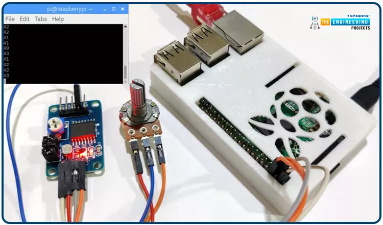
Welcome back to another Python tutorial for the Raspberry Pi 4! The previous tutorial showed us how to construct a Raspberry Pi-powered cell phone with a microphone and speaker for making and receiving calls and reading text messages (SMS). To make our Raspberry Pi 4 into a fully functional smartphone, we built software in Python. As we monitored text and phone calls being sent and received between the raspberry pi and our mobile phone, we experienced no technical difficulties. But in this tutorial, you'll learn how to hook up the PCF8591 ADC/DAC module to a Raspberry Pi 4.
Since most sensors only output their data in analog values, converting them to binary values that a microcontroller can understand is a crucial part of any integrated electronics project. A microcontroller's ability to process analog data necessitates using an analog-to-digital converter.
Some microcontrollers, including the Arduino, MSP430, and PIC16F877A, contain an onboard analog-to-digital converter (ADC), whereas others, like the 8051 and Raspberry Pi, do not.
Where To Buy? | ||||
---|---|---|---|---|
No. | Components | Distributor | Link To Buy | |
1 | Jumper Wires | Amazon | Buy Now | |
2 | PCF8591 | Amazon | Buy Now | |
3 | Raspberry Pi 4 | Amazon | Buy Now |
Raspberry-pi 4
PCF8591 ADC Module
100K Pot
Jumper wires
You are expected to have a Raspberry Pi 4 with the most recent version of Raspbian OS installed on it, and that you are familiar with using a terminal program like putty to connect to the Pi via the Internet and access its file system remotely. Those unfamiliar with Raspberry Pi can learn the basics by reading the articles below.
Each of the ten pins on the PCF8591 module may read analog values as high as 256 on the PCF8591's digital side or vice versa. The board has a thermistor and LDR circuit. Input and output from this module are both analogs. To facilitate the I2C protocol, it has a dedicated serial clock and serial data address pins. The supply voltage ranges from 2.5 to 6V, and the stand-by current is minimal. We can further turn the module's potentiometer knob to control the input voltage. A total of three jumpers can be found on the board. Switching between the thermistor, LDR/photoresistor, and adjustable voltage access circuits is possible by connecting J4, J5, and J6. D1 and D2 are two LEDs on the board, with D1 displaying the strength of the output voltage and D2 indicating the power of the supply voltage. When the supply or output voltage is increased, the brightness of LEDs D1 and D2 are correspondingly enhanced. Potentiometers connected to the LEDs' VCC or AOUT pins also allow testing.
Microprocessors, Arduinos, Raspberry Pis, and other digital logic circuits can interact with the physical environment thanks to Analogue-to-Digital Converters (ADCs). Many digital systems gather information about their settings by analyzing the analog signals produced by transducers such as microphones, light detectors, thermometers, and accelerometers. These signals constantly vary in value since they are derived from the physical world.
Digital circuits use binary signals, which can only be in one of two states, "1" (HIGH) or "0" (LOW), as opposed to the infinitely variable voltage values provided by analog signals (LOW). Therefore, Analogue-to-Digital Converters (A/D) is an essential electronic circuit for translating between constantly varying analog impulses and discrete digital signals.
To put it simply, an analog-to-digital converter (ADC) is a device that, given a single instantaneous reading of an analog voltage, generates a unique digital output code that stands in for that reading. The precision of an A/D converter determines how many binary digits, or bits, are utilized to represent the original analog voltage value.
By rotating the potentiometer's wiper terminal between 0 and VMAX, we may see a continuous output signal with an endless set of output values related to the wiper position. In a potentiometer, the output voltage constantly varies while the wiper is moved between fixed positions. Variations in temperature, pressure, liquid levels, and brightness are all examples of analog signals.
A digital circuit uses a single rotary switch to control the potential divider network, taking the place of the potentiometer's wiper at each node. The output voltage, VOUT, rapidly transitions from one node to the next as the switch is turned, with each node's value representing a multiple of 1.0 volts.
The output is guaranteed at 2-volt, 3-volt, 5 volts, etc., but NOT a 2.5-volt, 3.1-volt, or 4.6-volt output. Using a multi-position switch and more resistive components in the voltage-divider network, resulting in more discrete switching steps, would allow for generating finer output voltage levels.
By this definition, we can see that a digital signal has discrete (step-by-step) values, while an analog signal's values change continuously over time. We are going from "LOW" to "HIGH" or "HIGH" to "LOW."
So the question becomes how to transform an infinitely variable signal into one with discrete values or steps that a digital circuit can work with.
Although several commercially available analog-to-digital converter (ADC) chips exist, such as the ADC08xx family, for converting analog voltage signals to their digital equivalents, a primary ADC can be constructed out of discrete components.
Using comparators to detect various voltage levels and output their switching signal state to an encoder is a straightforward method known as parallel encoding, flash encoding, simultaneous encoding, or multiple comparator converters.
The equivalence output script for a given n-bit resolution is formed by a chain network of accuracy resistors and a series of comparators that are connected but equally spaced.
As soon as an analog signal is provided to the comparator input, it is evaluated with a reference voltage, making parallel converters advantageous because of their ease of construction and lack of need for timing clocks. The following comparator circuit may be of interest.
The LM339N is an analog comparator that compares the relative magnitudes of two voltage levels via its two analog inputs (one positive and one negative).
The comparator receives two signals, one representing the input voltage (VIN) and the other representing the reference value (VREF). The comparator's digital circuits state, "1" or "0," is determined by comparing two output voltages at the input of the comparator.
One input (VREF) receives a reference voltage, and the other input (VIN) receives the input voltage to be compared to it. Output is "OFF" by an LM339 comparator when the input power is lower than (VIN VREF) and "ON" when the input power is higher than the standard voltage (VIN > VREF). A comparator is a device to determine which of two voltages is greater.
Using the potential divider network established by R1 and R2, we can calculate VREF. If the two resistors are identical in value (R1 = R2), then the reference voltage will be half the input power (V/2). Therefore, like with a 1-bit ADC, the output of an open-collector comparator is HIGH if VIN is lower than V/2 and LOW otherwise.
However, by increasing the number of resistors in the voltage divider circuit, we can "divide" the voltage source by an amount equal to the ratio of the resistors' resistances. However, the number of comparators needed increases with the number of resistors in the voltage-divider network.
For an "n"-bit binary output, where "n" is commonly between 8 and 16 bits, a 2n- 1 comparator would be needed in general. As we saw previously, the comparator utilized by the one-bit ADC to determine whether or not VIN was more significant than the V/2 voltage output was 21 minus 1, which equals 1.
If we want to build a 2-bit ADC, we'll need 22-1 or "3" comparators since the 4-to-2-bit encoder circuitry depicted above requires four distinct voltage levels to represent the four digital values.
Where X is a "don't care" statement, representing a logical 0 or 1.
Explain how this analog-to-digital device operates. An analog-to-digital converter (A/D) must generate a faithful digital copy of the Analog input signal to be of any value. To keep things straightforward, we've assumed that VIN is somewhere between 0 and 4 volts and have adjusted VREF and the voltage divider network so that there is a 1 V drop between each resistor in this simple 2-bit Analog - to - digital example.
A binary zero (00) is output by the encoder on pins Q0 and Q1 when the input voltage, VIN, is less than the reference voltage level, which occurs when VIN is between 0 and 1 volts (1V). Since comparator U1's reference voltage input is set to 1 volt, when VIN rises above 1 volt but is below 2 volts, U1's HIGH output is triggered. When the input changes at D1, the priority encoder, used for the 4-to-2-bit encoding, generates a binary result of "1." (01).
Remember that the inputs of a Priority Encoder, like the TTL 74LS148, are all assigned different priority levels. The highest priority input is always used as the output of the priority encoder. So, when a higher priority input is available, lesser priority inputs are disregarded. Therefore, if there are many inputs simultaneously at logic state "1", only the input with high priority will have its output code reflected on D0 and D1.
Thus, now that VIN is greater than 2 volts—the next reference voltage level—comparator U2 will sense the difference and output HIGH. However, when VIN is more than 3 volts, the priority encoder will output a binary "3" (11), as input D2 has a high priority than inputs D0 and D1. Each comparator outputs a HIGH or LOW state to the encoder, generating 2-bit binary data between 00 and 11 as VIN decreases or changes between every reference voltage level.
This is great and all, but commercially available priority encoders, like the TTL, are 8-bit circuits, and if we use one of these, six of the binary numbers will go unused. A digital Ex-OR gate and a grid of signaling diodes can create a straightforward encoder circuit.
Before feeding the diodes, the results of the comparators go through an Exclusive-OR gate to be encoded. Whenever the diode is reverse biased, an external pull-down resistor is connected between the diodes' outputs and ground (0V) to maintain a LOW state and prevent the outputs from floating.
Also, as with the main board, the value of VIN controls which comparator sends a HIGH (or LOW) signal to the exclusive-OR gates, which provide a HIGH output if either of the inputs is HIGH but not both (the corresponding Boolean is Q = A.B + A.B). The AND-OR-NAND gates of combinational logic could also be used to build these Ex-OR gates.
The difficulty with both of these 4-to-2 converter designs is that the input analog voltage at VIN needs to vary by one full volt for the encoder to vary its output code, limiting the precision of the simple two-bit A/D converter to 1 volt. The output resolution can be improved by employing more comparators to convert to a three-bit A/D converter.
The aforementioned parallel ADC takes a voltage reading between 0 and over 3 volts as an analog input and turns it into a binary code with only 2 bits. Since there are 23 = 8 possible digital outputs from a 3-bit digital circuits system, the input analog voltage can be compared to a scale of eight voltages, each of which is one-eighth (1/8) of the voltage supply. This means that we can now measure to an accuracy of 0.5 (4/8) volts and that 23-1 comparators are needed to generate a binary code with a 3-bit resolution (from 000 (0) to 111 (7)).
This will provide us with a three-bit code for each of the eight potential values of the analog input of:
An "X" may be a logic 0 or a logic 1 to indicate a "don't care" state.
Then we can see that more comparators and power levels are required and more output binary bits when the ADC's resolution is increased.
Therefore, an analog-to-digital converter with a 4-bit resolution needs only 15 (24-1) comparators. An eight-bit resolution requires 255 (28-1) comparators. A 10-bit resolution needs 1023 comparators, etc. Therefore, the complexity of this type of Analog-to-Digital Converter circuit increases as the number of output bits increases.
Only if a few binary bits are needed to make a read on a display unit to represent the reference voltage of an input analog signal can a parallel or flashed A/D converter quickly be developed as part of a project due to its fast real-time conversion rate.
As an input interface circuit component, an analog signal from sensors or transducers is converted into a digital binary code by an analog-to-digital converter. Similarly, a digital binary code can be converted into a comparable analog quantity using a Digital-to-Analog Conversion for output interfacing to operate a motor or actuator or, more often, in audio applications.
Knowing the Raspberry Pi's I2C port pins and setting up the I2C connection in the pi 4 are the initial steps in using a PCF8591 with the Pi.
GPIO2 and GPIO3 on the Rpi Model are utilized for I2C communication in this guide.
Raspberry Pi I2C Configuration
Raspberry Pi lacks I2C support by default. Therefore, it must be activated before anything else. Turn on Raspberry Pi's I2C port.
First, open a terminal and enter sudo raspi-config.
The RPi 4 Software Configuration Tool has opened.
Third, activate the I2C by selecting Interfacing options.
Restart the Pi after enabling I2C.
The Raspberry Pi has to know the I2C address of the PCF8591 IC before communication can begin. You may get the address by linking the PCF8591's SDA and SCL pins to the Raspberry Pi's own SDA and SCL jacks. The 5-volts and GND pins should be connected as well.
You may find the address of an attached I2C device by opening a terminal and entering the following command.
sudo i2cdetect –y 1 or sudo i2cdetect –y 0
After locating the I2C address, the next step is constructing the circuit and setting up the required libraries to use PCF8591 and a Raspberry Pi 4.
The circuit diagram to interface the PCF8591 with the Raspberry Pi is straightforward. In this example of interfacing, we'll read the analog signal from any analog inputs and display them in the Raspberry Pi terminal. We have a 100K pot to adjust the settings.
Pi's GPIO2 and GPIO must be connected to the power supply and ground. Then, hook up GPIO3 and GPIO5 to SDA and SCL, respectively. Last but not least, link AIN0 to a 100K pot. Instead of using the Terminal to view the ADC values, a 16x2 LCD can be added.
The complete code and demo video are included after this guide.
To communicate with the I2C bus, you must first import the SMBus library and then use the time library to specify how long to wait before outputting the value.
import smbus
import time
Create some variables now. The I2C bus address is stored in the first variable, and the first analog input pin's address is stored in the second variable.
address = 0x48
A0 = 0x40
Next, we've invoked the library smbus's SMBus(1) function to create an object.
bus = smbus.SMBus(1)
The first line in the while instructs IC to take a reading from the first analog signal pin. Address information read from an Analog pin is saved as a numeric variable in the second line. Exit with the value printed.
While True:
bus.write_byte(address,A0)
value = bus.read_byte(address)
print(value)
time.sleep(0.1)
Finally, put the Python script in a file ending in.py and run it in the Raspberry Pi terminal with the command below.
python filename.py
Ensure that the I2C communication is turned on and that the pins are linked according to the diagram before running the code, or else you will get errors. It's time for the analog readings to appear in the terminal format below. The values gradually shift as you turn the pot's knob. Find out more about getting the software to work in
Here is the full Python script.
import smbus
import time
address = 0x48
bus = smbus.SMBus(1)
while True:
bus.write_byte(address,A0)
value = bus.read_byte(address)
print(value)
time.sleep(0.1)
We rely heavily on electronic gadgets in today's high-tech society. The digital signal is the driving force behind these digital devices. While most numbers are represented digitally, few still use analog notation. Thus, an ADC is employed to transform analog impulses into digital ones. ADC can be used in an infinite variety of contexts. Here are only a few examples of their use:
The digitized voice signal is used by cell phones. The voice is first transformed to digital form using an ADC before being sent to the cell phone's transmitter.
Digital photos and movies shot with a camera can be viewed on any computer or mobile device thanks to an analog-to-digital converter.
X-rays and MRIs are just two examples of medical imaging techniques that use ADC to go from Analog to digital before further processing. Then, they're adjusted so that everyone can follow along.
ADC converters can also transfer music from a cassette tape to a digital format, such as a CD or a USB flash drive.
The Analog-to-Digital Converter (ADC) in a digital oscilloscope converts analog signals to digital ones that can then be displayed and used for other reasons.
The air conditioner's built-in temperature sensors allow for consistent comfort levels. The onboard controller reads the temperature and makes adjustments based on the data it receives from the ADC.
Nowadays, practically everything has a digital counterpart, so every gadget must also include an ADC. For the simple reason that its operations require a digital domain accessible only via an analog-to-digital converter (ADC).
This piece taught us how to connect a Raspberry Pi 4 to a PCF8591 Analogue - to - digital decoder module. We have observed the output being shown as integers on our Terminal. We have also researched how the ADC generates its output signals. Here we will use OpenCV and a Raspberry Pi 4 to create a social distance detector.
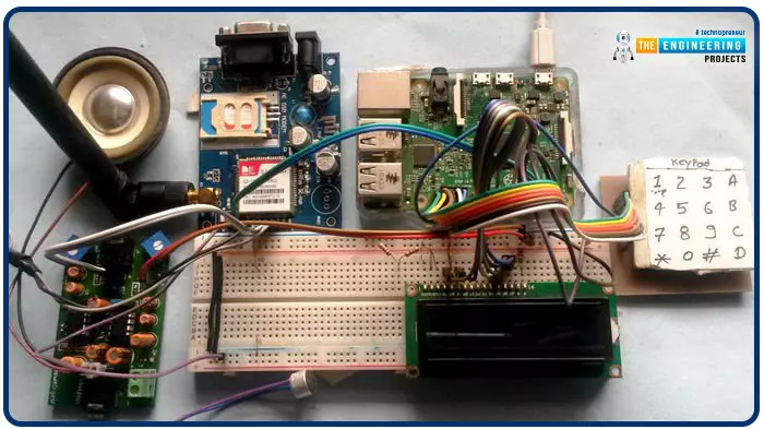
Greetings, and welcome to another tutorial in our series on the raspberry pi 4 Python programming. The previous guide covered the basics of transmitting data over the radio using the nrf24l01 chip in Pi 4. We also learned about interfacing Arduino and raspberry pi 4 and sending radio signals between the two devices. However, this tutorial will walk you through building a Raspberry Pi-based mobile phone with a microphone and speaker for making and receiving calls and reading text messages (SMS). This Project also serves as a proper GSM Module for the Raspberry Pi interface, with all the necessary Code to run the most fundamental features of any modern smartphone. First, we will understand what gsm is, its architecture and how it works, then we will learn how to program it in our pi 4; therefore, let us begin.
Where To Buy? | ||||
---|---|---|---|---|
No. | Components | Distributor | Link To Buy | |
1 | Jumper Wires | Amazon | Buy Now | |
2 | LCD 16x2 | Amazon | Buy Now | |
3 | Raspberry Pi 4 | Amazon | Buy Now |
Raspberry Pi 4
GSM Module
16x2 LCD
4 *4 Keypad
10k pot
Breadboard
Connecting jumper wire
Power supply
Speaker
Microphone
SIM Card
Loudspeaker
The acronym "GSM" refers to the "global system for mobile communication" and is the name of a type of mobile communication modem (GSM). Bell Labs was responsible for conceptualizing GSM in the 1970s. It's one of the most common forms of mobile communication around the globe. The 850MegaHertz, 900MegaHertz, 1800 Megahertz, and 1900 Megahertz frequency bands are utilized by GSM networks, which are part of an open and digital mobile network used to carry voice and data services.
Using the telecommunications method of multiple time division access (TDMA), GSM technology was created as a digital system. For transmission, a GSM converts analog signals to digital ones, compresses them further and delivers them through a channel sharing bandwidth with two data streams from separate clients. The data rates transported by the digital system range from 64 kilobytes per second to 120 Megabytes per second.
In a GSM network, macro, micro, and umbrella cells coexist. The implementation context determines the specifics of each cell. The macro, micro, and umbrella cell sizes are in use in a GSM network. Each cell may have a different range of coverage depending on the setting.
Time-division multiple access (TDMA) works by giving each user a specific amount of time to transmit on the same frequency. It's flexible, supporting data rates from 64kbps to 120Mbps and allowing for clear voice communications.
The following are the primary components of the GSM architecture.
Connectivity and Switching Infrastructure (NSS)
All three of these components—the Base Station (BS), the Mobile Station (MS), and the Operations and Maintenance Subsystem (OSS)—are necessary for proper communication (OSS)
Each component of the GSM system design contributes to what is collectively called the core system/network. In this case, the mobile network system is primarily controlled and interfaced with via a data network consisting of several different components. Listed below are some of the most crucial elements of the underlying network.
One of the essential parts of a GSM network is its core network, where the Mobile Switching Center (MSC) resides. This MSC performs the same functions as a common switching node in an ISDN or PSTN. Still, it provides additional features to accommodate mobile users' requirements, such as authentication, registration, inter-MSC handovers, call localization, and routing.
In addition, it gives users an advantage in connecting their mobile phone networks to the PSTN (public switched telephone network) for making and receiving landline calls. To facilitate mobile-to-mobile calls across different networks, interfaces to all other switched telephone networks ( PSTN center servers are given.
Every subscriber's administrative details, including their last known location, are stored in this HLR database. This manner, calls can be routed over the GSM network to the appropriate mobile switch base station. If a call comes in when an operator has their phone turned on, the network can determine which base transmitter station the call is coming from and link it to the correct phone.
When the phone is turned on but not being used, it nevertheless registers to ensure the HLR system is aware of its current location. Each network has a single HLR, which may be physically split across several data centers for practical reasons.
To facilitate the VLR's desired services for the individual subscriber, it incorporates data from the HLR network. It is possible to run the visitor coordinates register independently, but it is most commonly implemented as a core component of the MSC. Because of this, getting access is more manageable, and it takes less time overall.
The Equipment Identity Register (EIR) is the part of the network infrastructure in charge of deciding whether or not certain pieces of mobile equipment are allowed access. The International Mobile Equipment Identification (IMEI) numbers uniquely identify each mobile technology work.
This IMEI number is permanently embedded within the mobile device and checked by the network after registration. Depending on the data in the EIR, the mobile phone may be given one of three possible network access states: allowed, banned, or monitored.
When users insert their SIM card into their phone, the secret key is stored in a secure file known as the AUC (authentication center). The AUC sees the extensive application as a radio channel coding and verification standard.
In the absence of location information for the mobile station (MS), a call placed by a ME terminates with the GMSC (Gateway Mobile Switching Centre). Using the Mobile Subscriber Identifier Service Data Number (MSISDN) and the HLR, the GMSC can locate the specific MSC that has been visited and connect the call to the appropriate location. It's unclear what the "MSC" part of GMSC stands for, as the gateway procedure does not require relating to an MSC.
Both SMS-Gateways are referred to collectively as the SMS gateway in the GSM specifications. The messages passing via these gateways are directed in various ways.
Sending a short message to mobile equipment (ME) requires the usage of the Short Messaging Service Gateway Switching Center. Short messages sent over a mobile network are routed through the SMS Inter-Working Switching Center. While the SMS-primary GMSC's function concerns the GMSC, the SMS-IWMSC serves as a constant endpoint for access to the Short Message Service Centre.
These were the primary nodes in the GSM system's infrastructure. While they frequently shared physical space, the entire middle network would sometimes be broadcast throughout the country. In the event of a failure, it will provide a degree of leeway.
The connection point between the mobile node and the broader network infrastructure. The radio transceivers and protocol management for mobile devices are housed in the Base Transceiver Station. In addition, a Base Station Controller manages the Base Transceiver and serves as a bridge between mobile devices and the mobile switching hub.
The network subsystem handles connectivity between the network and the mobile stations. The Phone Service Switch Centre is the backbone of the Network Subsystem, allowing users to connect to other networks (ISDN, PSTN, etc.). The GSM system's ability to route calls and allow for roaming depends on two additional components, the Home Location Record and the guest Location Record.
In addition, it stores the Equipment Identity Register, which keeps track of all the mobile devices and their associated IMEI numbers. The acronym IMEI refers to the unique identifier for mobile devices worldwide.
In the second generation of GSM network design, the mobile devices communicate with the BSS, or Base Station Subsystem. These components comprise this subsystem, and each will be examined.
As part of a GSM network, the radio Tx, Rx, and their associated antennas make up the base Transceiver Station, which is used for transmitting, receiving, and communicating directly through mobiles. The base station is the central component of each cell, and it communicates with mobile devices using an interface known as the Um interface and related protocols.
The base station controller (BSC) is employed for the following step back into GSM technology. This controller is typically co-located within one of the base transceiver stations it controls. This controller handles radio resource management, including channel allocation and handover between base station groups. Over the Abis interface, it communicates with the BTSs.
The acceptable radio technology is used by the GSM network's subsystems component in the ground station to ensure that multiple operators can utilize the system at the same time. Each base station can support many operators because each channel can support up to eight users.
The network provider strategically places these to ensure comprehensive coverage. A base station, sometimes known as a "cell," can surround this space. Signals can't be prevented from bleeding into neighbouring cells, and the channels used in one don't transfer to the next.
Mobile phones include a transceiver, a display, and a CPU, all of which are network-connected and operated using a SIM card. In a GSM mobile transmission medium, the operator monitors and controls the mobile station or mobile equipment, which are most commonly represented by cell phones. Their size has shrunk significantly while their functionality has skyrocketed. The benefit of a much longer interval between charges is still another advantage. Phone hardware and the subscriber identity module (SIM) are two of many components.
A mobile device's hardware consists of its primary components, such as the housing, screen, battery, and electronics used to generate the signal and process the signal receiver before transmission. The IMEI is a unique number assigned to each mobile device. This feature can be permanently programmed into a phone throughout its manufacturing process. During the registration process, the network accesses this database to see if the device has been flagged as stolen.
A user's identity on the network is stored in the information contained in their SIMcard. It also includes other data, such as the IMSI number. With this IMSI stored in the Sim, the phone user could easily switch phones by swapping SIM cards. As a result, if switching to a new mobile phone were simple and didn't require a unique phone number, more people would do it, generating more revenue for network operators and contributing to GSM's overall economic triumph.
The OSS is an integral aspect of any functional GSM network. The NSS and BSC parts are linked here. The GSM network and BSS traffic load are the primary areas of focus for this OSS. It is worth noting that some preservation responsibilities are relocated to the base station controller to lower the maintenance expense of the system when the amount of BS increases through the consumer population growth.
The 2G GSM network architecture is predicated on a rational functioning method. This approach is remarkably straightforward compared to today's mobile network architectures, which rely on software-defined units to facilitate highly adaptable operations. However, the 2G GSM architecture will show how the necessary voice and essential operational functions are organized.
The following are some of the functions provided by the GSM module.
Enhanced spectrum efficiency
Features including "international roaming," "integrated services digital network" (ISDN) compatibility, and "support for future services" are also included.
High-quality voice communications; encrypted phone conversations;
Features like a programmable alarm clock, high-quality voice communication, a fixed calling number, a real-time clock, and the ability to send and receive SMS messages are all standard on modern smartphones (SMS)
As a result of its rigorous security measures, the GSM system is currently the safest available for use in the telecommunications industry. Call privacy and subscriber anonymity for GSM users are only protected during transmission, but this is still a massive step toward attaining end-to-end security.
In either its mobile phone or modem form, a Global System for Mobile Communications (GSM) modem enables two computers or processors to connect across a network. A SIM card is needed to run a GSM modem, and it can only be used within the coverage area the network provider has paid for. It has serial, USB, and Bluetooth connectivity options for linking to a personal computer.
Any regular GSM cell phone can double as a GSM modem if you have a suitable cable and driver installed on your PC. It would be best if you used a GSM modem instead of a GSM cell phone. The GSM modem is helpful in many devices, including POS terminals, inventory management systems, surveillance cameras, weather stations, and GPRS-mode remote data loggers.
Below is a circuit showing how to connect a GSM modem to the MC using the level-shifting IC Max232. When a numeric command is received by short message service (SMS) from any mobile device, the SIM card-mounted GSM modem transfers that information to the MC via serial connection. The GSM modem is programmed to respond to the order "STOP" by producing an MC output, the point which is utilized to deactivate the ignition switch.
If the input is driven low, the GSM modem will send a predetermined message (in this case, "ALERT") to the user. A 162 LCD screen displays the entirety of the procedure.
We have utilized a GSM module and a Raspberry Pi 4 to manage the entire system and interface its many parts in this Project. You can input data of any kind, including phone numbers, text messages, and phone calls, read and respond to text messages, and more, using a 4x4 alphanumeric keypad. The SIM900A GSM module connects mobile phones to wireless networks for making and receiving calls and sending and receiving text messages. We've integrated a microphone, a loudspeaker for making and receiving voice calls, and a 16 * 2 liquid crystal displays information like menu options and alarms.
With alphanumeric input, you can use the same keyboard to type in both numbers and letters. For the Code we used to allow alphabets in addition to numbers in this method, scroll down to the "Code in Code" section.
It's simple to put this plan into action. The alphanumeric keypad is used for all functions. Below you'll find a link to the complete Code and a demonstration video. This section will elaborate on the four aspects of the listed projects.
The Pi 4 phone we built requires us to press the letter "C" and provide the cellphone number we wish to call. We'll use an alphanumeric keyboard to enter the number. Once the correct number has been entered, we must hit "C" again. The AT command is now processed by pi 4 to connect the call to a specified number.
ATDxxxxxxxxxx; <Enter> where xxxxxxxxx is entered Mobile Number.
Answering a phone call is simple. When a call comes into the SIM number stored in the GSM Module of your system, the LCD will display the message "Incoming..." along with the caller's number. All that's left to do is hit the 'A' key to answer the call. Pi 4 will send the following command to the GSM Module when the "A" button is pressed:
ATA <enter>
Pressing "D" on our Raspberry Pi phone allows us to send a text message. To whom (or what) should we address the SMS message that the system has just requested? Once the number has been entered, pressing "D" again will prompt the LCD to request a message. To send an SMS, enter the message using the keypad as you would with any other mobile device, and then hit the 'D' key again. Raspberry Pi can send SMS with the following command:
AT+CMGF=1 <enter>
AT+CMGS=”xxxxxxxxxx” <enter> where: xxxxxxxxxx is entered mobile number
Even this component is easy to use. Here, the SIM card is used to receive SMS messages from the GSM. The Raspberry Pi also keeps a close eye on the UART SMS signal. New notes are shown by the LCD displaying the text "New message," and reading them is as simple as pressing the "B" key. This is an SMS Received signal:
+CMTI: "SM," 6 Where 6 is the message location where it is stored in the SIM card.
When the RPi detects the 'SMS received' signal, it will get the SMS storage location and instruct the Global system for mobile to read the message. Moreover, the LCD will flash the words "New Message" in a prominent location.
AT+CMGR=<SMS stored location><enter>
The GSM now delivers the saved message to the Raspberry Pi, and the Pi, having extracted the primary SMS, shows it on the LCD. When it comes to MIC and Speaker, there is no secret code.
The GPIO pins of the Raspberry Pi are wired to the RS, EN, D4, D5, D6, and D7 pins of the 16 * 2 liquid crystal display. A direct connection is made between the GSM module's Rx and Tx pins and the Raspberry Pi's Tx and Rx pins. Connectors R1, R2, R3, and R4 of a 4 * 4 keypad are connected to GPIOs 12, 16, 20, and 21, whereas pins C1, C2, C3, and C4 are connected to GPIOs 26, 19, 13, and 6. If you want to boost the audio volume from the GSM Module, you can join the microphone directly to the mic+ and mic- pins and the loudspeaker to the sp+ and sp- pins. The loudspeaker can be connected directly to the GSM module without using the Audio Amplifier circuit.
This Pi 4 mobile phone's programming interface may be challenging to novices—the programming language of choice for this Project is Python.
Here, we define the keypad() function to be used with a basic numeric keypad. We've also added a def alpha keypad(): for typing alphabets so that you may use the same keypad for both purposes. To make it compatible with the Arduino keypad library, we've given this keypad a wide range of new capabilities. This keypad only takes 10 presses to enter a whole string of text or a numeric value.
For example, if we push key 2 (abc2) once, the LCD will display the letter 'a.' If we press it again, the letter 'b' will take its place, and if we hit it three more times, the letter 'c' will appear in the same spot. After holding down a key for a short time, the LCD pointer will advance to the following available location. We can now proceed to the next character or number. Any other keys can be processed in the same way.
def keypad():
for j in range(4):
gpio.setup(COL[j], gpio.OUT)
gpio.output(COL[j], 0)
ch=0
for i in range(4):
if gpio.input(ROW[i])==0:
ch=MATRIX[i][j]
return ch
while (gpio.input(ROW[i]) == 0):
pass
gpio.output(COL[j],1)
def alphaKeypad():
lcdclear()
setCursor(x,y)
lcdcmd(0x0f)
msg=""
while 1:
key=0
count=0
key=keypad()
if key == '1':
ind=0
maxInd=6
Key='1'
getChar(Key, ind, maxInd)
.... .....
..... .....
To begin, we have declared the pins for the liquid crystal display, the keypad, and other components, as well as included the necessary libraries in this python script:
import RPi.GPIO as gpio
import serial
import time
msg=""
alpha="1!@.,:?ABC2DEF3GHI4JKL5MNO6PQRS7TUV8WXYZ90 *#"
x=0
y=0
MATRIX = [
['1','2','3','A'],
['4','5','6','B'],
['7','8','9','C'],
['*','0','#','D']
]
ROW = [21,20,16,12]
COL = [26,19,13,6]
... .....
..... .....
The pins need to be pointed in the proper direction.
gpio.setwarnings(False)
gpio.setmode(gpio.BCM)
gpio.setup(RS, gpio.OUT)
gpio.setup(EN, gpio.OUT)
gpio.setup(D4, gpio.OUT)
gpio.setup(D5, gpio.OUT)
gpio.setup(D6, gpio.OUT)
gpio.setup(D7, gpio.OUT)
gpio.setup(led, gpio.OUT)
gpio.setup(buz, gpio.OUT)
gpio.setup(m11, gpio.OUT)
gpio.setup(m12, gpio.OUT)
gpio.setup(button, gpio.IN)
gpio.output(led , 0)
gpio.output(buz , 0)
gpio.output(m11 , 0)
gpio.output(m12 , 0)
To begin Serial communication, follow the steps below.
Serial = serial.Serial("/dev/ttyS0", baudrate=9600, timeout=2)
We must now create a liquid crystal display driving function. The def lcdcmd(ch): and def lcdwrite(ch): functions are used to deliver commands and data to the LCD, respectively. The liquid crystal display may also be cleared with def lcdclear(), the cursor position can be set with def setCursor(x,y), and a string can be sent to the liquid crystal display with def lcdprint(Str).
def lcdcmd(ch):
gpio.output(RS, 0)
gpio.output(D4, 0)
gpio.output(D5, 0)
gpio.output(D6, 0)
gpio.output(D7, 0)
if ch&0x10==0x10:
gpio.output(D4, 1)
.... .....
..... ....
def lcdwrite(ch):
gpio.output(RS, 1)
gpio.output(D4, 0)
gpio.output(D5, 0)
gpio.output(D6, 0)
gpio.output(D7, 0)
if ch&0x10==0x10:
gpio.output(D4, 1)
if ch&0x20==0x20:
gpio.output(D5, 1)
.... .....
..... ....
def lcdclear():
lcdcmd(0x01)
def lcdprint(Str):
l=0;
l=len(Str)
for i in range(l):
lcdwrite(ord(Str[i]))
def setCursor(x,y):
if y == 0:
n=128+x
elif y == 1:
n=192+x
lcdcmd(n)
Next, we'll need to code some features for interacting with text messages, phone calls, and incoming calls.
The call is placed using the function def call():. Also, the LCD can display the receiving message and number via the function def receiveCall(data):. Finally, the call is answered with def attendCall():.
The message is composed and sent using the alphaKeypad() method, accessed via the def sendSMS(): function. The SMS is received, and its location is retrieved using the def receive SMS(data) function. And finally, the LCD gets updated with the message thanks to def readSMS(index:).
All of the operations mentioned above are included in the Code that follows.
import RPi.GPIO as gpio
import serial
import time
msg=""
# 0 7 11 15 19 23 27 32 36 414244 ROLL45
alpha="1!@.,:?ABC2DEF3GHI4JKL5MNO6PQRS7TUV8WXYZ90 *#"
x=0
y=0
MATRIX = [
['1','2','3','A'],
['4','5','6','B'],
['7','8','9','C'],
['*','0','#','D']
]
ROW = [21,20,16,12]
COL = [26,19,13,6]
moNum=['0','0','0','0','0','0','0','0','0','0']
m11=17
m12=27
led=5
buz=26
button=19
RS =18
EN =23
D4 =24
D5 =25
D6 =8
D7 =7
HIGH=1
LOW=0
gpio.setwarnings(False)
gpio.setmode(gpio.BCM)
gpio.setup(RS, gpio.OUT)
gpio.setup(EN, gpio.OUT)
gpio.setup(D4, gpio.OUT)
gpio.setup(D5, gpio.OUT)
gpio.setup(D6, gpio.OUT)
gpio.setup(D7, gpio.OUT)
gpio.setup(led, gpio.OUT)
gpio.setup(buz, gpio.OUT)
gpio.setup(m11, gpio.OUT)
gpio.setup(m12, gpio.OUT)
gpio.setup(button, gpio.IN)
gpio.output(led , 0)
gpio.output(buz , 0)
gpio.output(m11 , 0)
gpio.output(m12 , 0)
for j in range(4):
gpio.setup(COL[j], gpio.OUT)
gpio.setup(COL[j],1)
for i in range (4):
gpio.setup(ROW[i],gpio.IN,pull_up_down=gpio.PUD_UP)
Serial = serial.Serial("/dev/ttyS0", baudrate=9600, timeout=2)
data=""
def begin():
lcdcmd(0x33)
lcdcmd(0x32)
lcdcmd(0x06)
lcdcmd(0x0C)
lcdcmd(0x28)
lcdcmd(0x01)
time.sleep(0.0005)
def lcdcmd(ch):
gpio.output(RS, 0)
gpio.output(D4, 0)
gpio.output(D5, 0)
gpio.output(D6, 0)
gpio.output(D7, 0)
if ch&0x10==0x10:
gpio.output(D4, 1)
if ch&0x20==0x20:
gpio.output(D5, 1)
if ch&0x40==0x40:
gpio.output(D6, 1)
if ch&0x80==0x80:
gpio.output(D7, 1)
gpio.output(EN, 1)
time.sleep(0.005)
gpio.output(EN, 0)
# Low bits
gpio.output(D4, 0)
gpio.output(D5, 0)
gpio.output(D6, 0)
gpio.output(D7, 0)
if ch&0x01==0x01:
gpio.output(D4, 1)
if ch&0x02==0x02:
gpio.output(D5, 1)
if ch&0x04==0x04:
gpio.output(D6, 1)
if ch&0x08==0x08:
gpio.output(D7, 1)
gpio.output(EN, 1)
time.sleep(0.005)
gpio.output(EN, 0)
def lcdwrite(ch):
gpio.output(RS, 1)
gpio.output(D4, 0)
gpio.output(D5, 0)
gpio.output(D6, 0)
gpio.output(D7, 0)
if ch&0x10==0x10:
gpio.output(D4, 1)
if ch&0x20==0x20:
gpio.output(D5, 1)
if ch&0x40==0x40:
gpio.output(D6, 1)
if ch&0x80==0x80:
gpio.output(D7, 1)
gpio.output(EN, 1)
time.sleep(0.005)
gpio.output(EN, 0)
# Low bits
gpio.output(D4, 0)
gpio.output(D5, 0)
gpio.output(D6, 0)
gpio.output(D7, 0)
if ch&0x01==0x01:
gpio.output(D4, 1)
if ch&0x02==0x02:
gpio.output(D5, 1)
if ch&0x04==0x04:
gpio.output(D6, 1)
if ch&0x08==0x08:
gpio.output(D7, 1)
gpio.output(EN, 1)
time.sleep(0.005)
gpio.output(EN, 0)
def lcdclear():
lcdcmd(0x01)
def lcdprint(Str):
l=0;
l=len(Str)
for i in range(l):
lcdwrite(ord(Str[i]))
def setCursor(x,y):
if y == 0:
n=128+x
elif y == 1:
n=192+x
lcdcmd(n)
def keypad():
for j in range(4):
gpio.setup(COL[j], gpio.OUT)
gpio.output(COL[j], 0)
ch=0
for i in range(4):
if gpio.input(ROW[i])==0:
ch=MATRIX[i][j]
#lcdwrite(ord(ch))
# print "Key Pressed:",ch
# time.sleep(2)
return ch
while (gpio.input(ROW[i]) == 0):
pass
gpio.output(COL[j],1)
# callNum[n]=ch
def serialEvent():
data = Serial.read(20)
#if data != '\0':
print data
data=""
def gsmInit():
lcdclear()
lcdprint("Finding Module");
time.sleep(1)
while 1:
data=""
Serial.write("AT\r");
data=Serial.read(10)
print data
r=data.find("OK")
if r>=0:
break
time.sleep(0.5)
while 1:
data=""
Serial.write("AT+CLIP=1\r");
data=Serial.read(10)
print data
r=data.find("OK")
if r>=0:
break
time.sleep(0.5)
lcdclear()
lcdprint("Finding Network")
time.sleep(1)
while 1:
data=""
Serial.flush()
Serial.write("AT+CPIN?\r");
data=Serial.read(30)
print data
r=data.find("READY")
if r>=0:
break
time.sleep(0.5)
lcdclear()
lcdprint("Finding Operator")
time.sleep(1)
while 1:
data=""
Serial.flush()
Serial.read(20)
Serial.write("AT+COPS?\r");
data=Serial.read(40)
#print data
r=data.find("+COPS:")
if r>=0:
l1=data.find(",\"")+2
l2=data.find("\"\r")
operator=data[l1:l2]
lcdclear()
lcdprint(operator)
time.sleep(3)
print operator
break;
time.sleep(0.5)
Serial.write("AT+CMGF=1\r");
time.sleep(0.5)
# Serial.write("AT+CNMI=2,2,0,0,0\r");
# time.sleep(0.5)
Serial.write("AT+CSMP=17,167,0,0\r");
time.sleep(0.5)
def receiveCall(data):
inNumber=""
r=data.find("+CLIP:")
if r>0:
inNumber=""
inNumber=data[r+8:r+21]
lcdclear()
lcdprint("incoming")
setCursor(0,1)
lcdprint(inNumber)
time.sleep(1)
return 1
def receive SMS(data):
print data
r=data.find("\",")
print r
if r>0:
if data[r+4] == "\r":
smsNum=data[r+2:r+4]
elif data[r+3] == "\r":
smsNum=data[r+2]
elif data[r+5] == "\r":
smsNum=data[r+2:r+5]
else:
print "else"
print smsNum
if r>0:
lcdclear()
lcdprint("SMS Received")
setCursor(0,1)
lcdprint("Press Button B")
print "AT+CMGR="+smsNum+"\r"
time.sleep(2)
return str(smsNum)
else:
return 0
def attendCall():
print "Attend call"
Serial.write("ATA\r")
data=""
data=Serial.read(10)
l=data.find("OK")
if l>=0:
lcdclear()
lcdprint("Call attended")
time.sleep(2)
flag=-1;
while flag<0:
data=Serial.read(12);
print data
flag=data.find("NO CARRIER")
#flag=data.find("BUSY")
print flag
lcdclear()
lcdprint("Call Ended")
time.sleep(1)
lcdclear()
def readSMS(index):
print index
Serial.write("AT+CMGR="+index+"\r")
data=""
data=Serial.read(200)
print data
r=data.find("OK")
if r>=0:
r1=data.find("\"\r\n")
msg=""
msg=data[r1+3:r-4]
lcdclear()
lcdprint(msg)
print msg
time.sleep(5)
lcdclear();
smsFlag=0
print "Receive SMS"
def getChar(Key, ind, maxInd):
ch=0
ch=ind
lcdcmd(0x0e)
Char=''
count=0
global msg
global x
global y
while count<20:
key=keypad()
print key
if key== Key:
setCursor(x,y)
Char=alpha[ch]
lcdwrite(ord(Char))
ch=ch+1
if ch>maxInd:
ch=ind
count=0
count=count+1
time.sleep(0.1)
msg+=Char
x=x+1
if x>15:
x=0
y=1
lcdcmd(0x0f)
def alphaKeypad():
lcdclear()
setCursor(x,y)
lcdcmd(0x0f)
msg=""
while 1:
key=0
count=0
key=keypad()
if key == '1':
ind=0
maxInd=6
Key='1'
getChar(Key, ind, maxInd)
elif key == '2':
ind=7
maxInd=10
Key='2'
getChar(Key, ind, maxInd)
elif key == '3':
ind=11
maxInd=14
Key='3'
getChar(Key, ind, maxInd)
elif key == '4':
ind=15
maxInd=18
Key='4'
getChar(Key, ind, maxInd)
elif key == '5':
ind=19
maxInd=22
Key='5'
getChar(Key, ind, maxInd)
elif key == '6':
ind=23
maxInd=26
Key='6'
getChar(Key, ind, maxInd)
elif key == '7':
ind=27
maxInd=31
Key='7'
getChar(Key, ind, maxInd)
elif key == '8':
ind=32
maxInd=35
Key='8'
getChar(Key, ind, maxInd)
elif key == '9':
ind=36
maxInd=40
Key='9'
getChar(Key, ind, maxInd)
elif key == '0':
ind=41
maxInd=42
Key='0'
getChar(Key, ind, maxInd)
elif key == '*':
ind=43
maxInd=43
Key='*'
getChar(Key, ind, maxInd)
elif key == '#':
ind=44
maxInd=44
Key='#'
getChar(Key, ind, maxInd)
elif key== 'D':
return
def sendSMS():
print"Sending sms"
lcdclear()
lcdprint("Enter Number:")
setCursor(0,1)
time.sleep(2)
moNum=""
while 1:
key=0;
key=keypad()
#print key
if key>0:
if key == 'A' or key== 'B' or key== 'C':
print key
return
elif key == 'D':
print key
print moNum
Serial.write("AT+CMGF=1\r")
time.sleep(1)
Serial.write("AT+CMGS=\"+91"+moNum+"\"\r")
time.sleep(2)
data=""
data=Serial.read(60)
print data
alphaKeypad()
print msg
lcdclear()
lcdprint("Sending.....")
Serial.write(msg)
time.sleep(1)
Serial.write("\x1A")
while 1:
data=""
data=Serial.read(40)
print data
l=data.find("+CMGS:")
if l>=0:
lcdclear()
lcdprint("SMS Sent.")
time.sleep(2)
return;
l=data.find("Error")
if l>=0:
lcdclear()
lcdprint("Error")
time.sleep(1)
return
else:
print key
moNum+=key
lcdwrite(ord(key))
time.sleep(0.5)
def call():
print "Call"
n=0
moNum=""
lcdclear()
lcdprint("Enter Number:")
setCursor(0,1)
time.sleep(2)
while 1:
key=0;
key=keypad()
#print key
if key>0:
if key == 'A' or key== 'B' or key== 'D':
print key
return
elif key == 'C':
print key
print moNum
Serial.write("ATD+91"+moNum+";\r")
data=""
time.sleep(2)
data=Serial.read(30)
l=data.find("OK")
if l>=0:
lcdclear()
lcdprint("Calling.....")
setCursor(0,1)
lcdprint("+91"+moNum)
time.sleep(30)
lcdclear()
return
#l=data.find("Error")
#if l>=0:
else:
lcdclear()
lcdprint("Error")
time.sleep(1)
return
else:
print key
moNum+=key
lcdwrite(ord(key))
n=n+1
time.sleep(0.5)
begin()
lcdcmd(0x01)
lcdprint(" Mobile Phone ")
lcdcmd(0xc0)
lcdprint(" Using RPI ")
time.sleep(3)
lcdcmd(0x01)
lcdprint("Circuit Digest")
lcdcmd(0xc0)
lcdprint("Welcomes you")
time.sleep(3)
gsmInit()
smsFlag=0
index=""
while 1:
key=0
key=keypad()
print key
if key == 'A':
attendCall()
elif key == 'B':
readSMS(index)
smsFlag=0
elif key == 'C':
call()
elif key == 'D':
sendSMS()
data=""
Serial.flush()
data=Serial.read(150)
print data
l=data.find("RING")
if l>=0:
callstr=data
receiveCall(data)
l=data.find("\"SM\"")
if l>=0:
smsstr=data
smsIndex=""
(smsIndex)=receiveSMS(smsstr)
print smsIndex
if smsIndex>0:
smsFlag=1
index=smsIndex
if smsFlag == 1:
lcdclear()
lcdprint("New Message")
time.sleep(1)
setCursor(0,0)
lcdprint("C--> Call <--A");
setCursor(0,1);
lcdprint("D--> SMS <--B")
Here are some examples of how GSM technology can be put to use.
Automation and Safety via Smart GSM Technology
Nowadays, we can't live without our GSM mobile terminal. The Mobile phone terminal is essentially an extension of ourselves, allowing us to connect with the world in the same way our wallet/purse, keys, or watch does. Many people like not having to worry about being unavailable or who they can call at any given moment.
It's clear from the name that this Project relies on the SMS transmission capabilities of GSM networks. The ability to send and receive text messages is widely utilized to provide access to equipment and facilitate home security breach management. There are two proposed subsystems in the system. Controlling appliances in one's house from afar is made possible by the appliance control subsystem, while the security alert subsystem provides automatic security monitoring.
The system can send consumers instructions via SMS from a designated phone number to adjust the home appliance's state as needed. An automatic SMS can be generated by the system upon detection of an intrusion, warning the user of a potential threat to their data.
The advent of GSM technology will make global, instantaneous, and universal communication possible. GSM's functional architecture employs intelligent networking principles as the first step toward a genuinely personal communication system with sufficient standards to ensure interoperability.
Medical Uses for GSM-Based Systems
Here are two examples of similar situations to think about.
The patient has sustained a life-threatening injury or illness and requires emergency medical attention. A mobile phone is the only thing he (or his companion) has.
After being released from the hospital, the patient plans to rest at home but is reminded that he must return for routine exams. A mobile phone and perhaps some health monitoring or other medical sensor gadgets may be in his possession.
The only way to solve either problem is via a mobile communication system. In other words, the above scenarios are easily manageable with today's communication technology because all that needs to be done is send the patient's information across a network and have it processed at the receiving end, which may be a hospital or the doctor's office.
In the first scenario, the doctor keeps tabs on the patient's information and returns the instructions to him so he can take whatever precautions before getting to the hospital. In the second scenario, the doctor keeps tabs on the patient's test results and, if necessary, proceeds with treatment.
Telemedicine services are the driving force behind this entire operation. The telemedicine system has three different applications.
Video conferencing lets patients in one location have face-to-face contact with their doctors and nurses, speeding up the healing process.
With the help of sensors that constantly report on a patient's condition and direct medical staff on how to proceed with treatment.
By sending the gathered health information for further review and analysis.
A wireless method of communication is used for the three options mentioned above. When providing healthcare, it is necessary to have many data retrieval mechanisms in place. These can be online medical databases or hosts with equipment that aid recovery and health monitoring. Broadband networks, medium-throughput media, and narrowband GSM access are all viable possibilities.
There are several benefits to using GSM technology in a telemedicine setup.
Cost savings and widespread availability of GSM receivers (including cell phones and modems)
It can transfer data quickly.
Typical Telemedical Infrastructure
The four components that make up a standard telemedicine system are as follows:
The Patient Unit: It takes data from the patient, either in its original analog form or after being converted to digital format, and then manages the data stream before sending it. It is made up of several different types of medical sensors, such as those used to track heart rate, blood pressure, body temperature, spirometry, etc., each of which generates an electrical signal that is sent to a processor or controller for analysis before being transmitted over a wireless network.
Communication Network: As such, it is employed for both data transmission and security. Networks, mobile stations, and base stations are all components of the Global System for Mobile Communication (GSM) system. The mobile station, also known as the mobile phone or primary mobile access point, is the device responsible for connecting mobile devices to the global system for mobile communications (GSM) network.
Receiving/Server Side: This is a healthcare system with a GSM modem installed to receive, decode, and forward signals to the presenting device.
Presentation Unit: This is the brains of the operation. This processor saves the data in a standard format for later retrieval and analysis by doctors and from which they can send text messages to the client side if necessary.
To demonstrate the fundamentals of telemedicine, a rudimentary model will suffice. It has a sender and a receiver, both of which are separate components. The sensor input is transmitted by the transmitter and received by the receiver unit for processing.
See below for a simplified telemedicine system to track a patient's heart rate and apply the results as needed.
The data collected by the heartbeat detector (a light-emitting device whose light is modified as it flows through human blood) is transformed into electrical pulses at the transmitter unit. When the Microcontroller picks up on these pulses, it calculates the heart rate and communicates that information and other data collected to the medical team via a Gsm network. An IC called a Max 232 connects the Microcontroller to the GSM modem.
The GSM modem at the receiving end grabs the information and passes it to the Microcontroller. The Microcontroller then performs an analysis using the input from the Personal computer and displays the outcome on the LCD. Medical professionals can keep tabs on the patient and begin the necessary treatment after reviewing the results on the screen.
The following are some real-world applications for GSM technology.
AT&T Health GlowCaps
These plain pill bottles serve as a gentle prompt to the patient to take their prescribed medications. It uses GSM technology to contact the patient on their mobile phone at the specified pill-taking time, at which point the cap will light up, the buzzer will sound, and the patient will be reminded to take their medication. Each time a bottle is uncorked, it is documented.
Ultrasound technology
With the help of a portable ultrasound transducer that connects to a smartphone, it is possible to send ultrasound images captured with a handheld device to a distant location using a global system for mobile communications (GSM).
A Continuous Glucose Monitor (CGM)
The patient's blood sugar levels can be tracked and reported to the doctor. A sensor is implanted under the skin and monitors blood glucose levels, sending the data to a receiver (a mobile phone) at regular intervals.
As part of this guide, we analyzed GSM's architecture and learned how it operates in practice. We wrote a Python program to turn our Raspberry Pi 4 into a fully functional mobile phone. No technical difficulties were encountered as we watched text and phone calls travel between the raspberry pi and our mobile phone. You should feel confident in your ability to apply the ideas and understand the circuits of GSM now. One way to up the difficulty level of this Project is to try to make a live video call using the raspberry pi 4 mobile. Next, we'll look at connecting the pcf8591 ADC/DAC analog-digital converter module to a Raspberry Pi.
Where To Buy? | ||||
---|---|---|---|---|
No. | Components | Distributor | Link To Buy | |
1 | Breadboard | Amazon | Buy Now | |
2 | Jumper Wires | Amazon | Buy Now | |
3 | LCD 16x2 | Amazon | Buy Now | |
4 | nRF24L01 | Amazon | Buy Now | |
5 | Arduino Uno | Amazon | Buy Now | |
6 | Raspberry Pi 4 | Amazon | Buy Now |
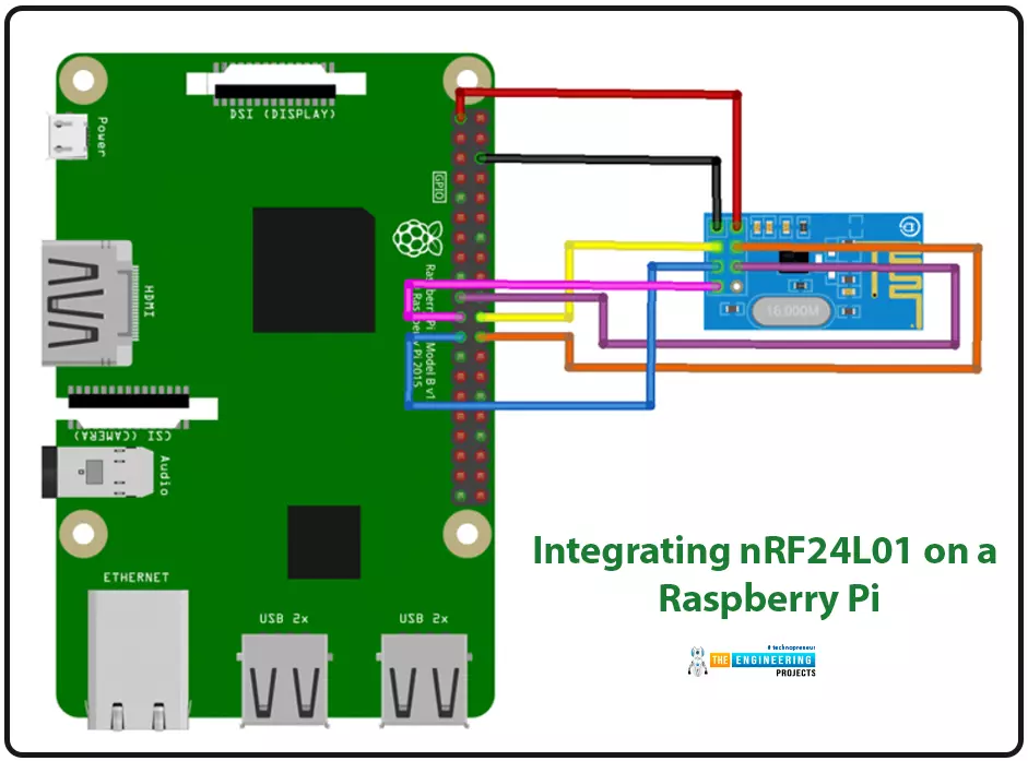
We're glad you could join us for another lesson in our series on programming for the Raspberry Pi 4. The previous chapter covered how to interface the USB barcode scanner with raspberry pi 4. We looked at different types of barcodes and what each stripe represents as well as the different types of barcode scanners available today. We also built a python program for the intelligent shopping cart and now our familiarity with barcodes and scanners and how they function has significantly increased. The benefits and drawbacks of its use were also discussed, but what we're interested in for this article is the transmission of radio frequency signals using the nrf24l01 Module in a raspberry pi 4.
nRF24L01 RF module
Raspberry pi 4
Arduino Uno
Jumper wires
Power supply
16x2 liquid crystal display
Wireless communication systems, such as ESPS266 WiFi modules, are widely used in the design process. Further, the media chosen is determined by the function it will serve. It's no secret that the nRF24L01 is a widely used wireless channel for local area network communication. These modules have a band rate of 250Kbps to 2Mbps and transmit on the 2.4GHz (ISM band), which is permitted in many states and suitable for usage in industrial and healthcare settings. There is also the claim that these modules can communicate at a distance of up to 100 meters with the correct antennae.
This tutorial demonstrates how to set up wireless communication between an Arduino UNO and a Raspberry Pi by utilizing the nRF24L01 - 2.4GHz RF Transceiver module. Raspberry Pi will broadcast data via nRF24L01, and Arduino Board will receive the data and display it on a 16x2 LCD. In addition to its built-in WiFi and Bluetooth Low Energy (BLE) capabilities, the nRF24L01 is also capable of wireless communication via BLE.
Both parts of the tutorial are equally important. In the first, we'll see how to connect the nRF24L01 to an Arduino so that it can function as a receiver, and in the second, we'll do the same thing with a Raspberry Pi can send out signals.
There are many different types of electromagnetic waves. Still, the ones utilized for radar signals and communications fall into roughly 3 kHz to 300 GHz range, known as "radio frequencies."
The term "radio frequency" is more commonly used to refer to electrical than mechanical oscillations. There are, however, examples of mechanical RF systems. Although radio frequency (RF) refers to an oscillation rate, the term "radio frequency" (RF) is sometimes used interchangeably with "radio" to describe the practice of communicating without the need for wires.
Numerous wireless technologies rely on RF fields, including cordless and cell phones, radio and television broadcasting stations, satellite telecommunication networks, Bluetooth communication modules and WiFi, and two-way radios.
External communications include various products like garage doors and microwave ovens, which use radio frequencies. The infrared frequencies of various wireless devices, like TV remote controllers, computer mice, and some wireless computer keyboards, have shorter electromagnetic wavelengths.
The frequency of radio transmission is expressed in hertz (Hz) units, which stand for the count of cycles per second. Radio waves can travel from one thousand hertz (kHz) to several gigahertz (GHz). Microwaves, a form of radio wave, operate at much higher frequencies. Because of this, we can't see radio frequencies (RFs).
The wavelength' of a radio wave is proportional to the square root of the frequency 'f.' The relationship between frequency and wavelength can be expressed in megahertz and meters, respectively.
s = 300/f
At higher frequencies, electromagnetic radiation is manifested as infrared (IR), ultraviolet (UV), visible (Visible), X-ray (XR), and gamma-ray (GJ).
The following are some of the defining features of RF:
Low energy consumption
It has an excellent operational range (three to thirty meters), a data rate of up to two megabits per second, the ability to pass through walls, and can transmit in any direction.
Due to their half-duplex design, the nRF24L01 modules can only send or receive data but not do both. The Module's data transmission and reception are handled by the generic Nordic semi-conductor nRF24L01 IC. The IC uses the simple serial peripheral interface (SPI) protocol for communication, making it compatible with virtually all microcontrollers. Arduino makes things much simpler because there are numerous library resources available. The following table depicts the pin configurations of a typical nRF24L01 module.
The Module is battery efficient, as its operating voltage ranges from 1.9V to 3.6V, and it draws minimal current (only 12mA) during regular operation. Most pins can be connected directly with 5V chipsets like Arduino, even though the voltage rating is 3.3V. Each Module also includes 6 Pipelines, which is a huge time saver. Simply put, each Module can exchange information with up to six others. Therefore, the Module can be used for IoT applications requiring the creation of star or mesh networks. With an extensive network address of 125 unique IDs, we may use 125 such components in a contained space without worrying about them interfering with one another.
Given that the Module supports 125 separate channels, creating a network containing 125 fully available modems at a single location is theoretically possible. Each device can simultaneously interface with up to six others on the same channel.
Transmission with this Module only uses about 12mA of power, less than a single display LED screen. The Module requires a voltage of 1.9V to 3.6V to function. Still, the other pins are 5V logic compatible, allowing us to connect it directly to an Arduino without needing logic-level converters.
Three of these terminals are used for SPI communication and must be hooked up to the SPI pins on the Arduino; however, the SPI pins on different Arduino boards are labelled differently. Connecting the CSN and CE pins to any input pin on the Arduino board toggles between standby and active modes and transmit and command modes for the Module. The last connector is an interrupt pin, which is optional.
The NRF24L01 modules can be found in a wide range of versions. The model with a built-in antenna is the clear frontrunner. This reduces the transmission range of the Module to around 100 meters but allows for a smaller module size.
In the second variant, an SMA connector replaces the onboard antenna, allowing us to use a duck transmitter for enhanced signal strength.
The third variant displayed here also features the duck antenna with an RFX2401C microprocessor with an integrated Power Amplifier and Low-Noise Amplifier). This can increase the NRF24L01's transmission range in open areas by 1000.
The components in the circuit design for linking nRF24L01 to Arduino are few, and the process is straightforward. SPI will be used to link the nRF24l01, and I2C will connect the 16x2 LCD.
Because only the SPI adapter is required to link the Raspberry Pi and the nRF24L01, the corresponding circuit schematic is pretty straightforward.
Python3 will be used for Raspberry Pi's programming. The Arduino platform is not the only one that can use C/C++. However, if you're programming in Python, you can get a library for nRF24l01 that's already been made. Keep in mind that the library and the python program must be in the same folder for the python program to use it. Create a folder to house your applications and library files after you have downloaded and extracted the library. After the necessary libraries have been installed, you can begin coding immediately. Importing libraries like the GPIO library for communicating with the Raspberry Pi's GPIO pins and the time library for using the Pi's clock and date functions are the first steps in writing any program.
import RPi.GPIO as GPIO
import time
import spidev
from lib_nrf24 import NRF24
It would be best if you switched to the "Broadcom SOC channel" for the GPIO setting. Pins are referred to by their "Broadcom SOC channel" numbers, which follow the letters "GPIO" (GPIO01, GPIO02, etc.). The Board Numbers are not these.
GPIO.setmode(GPIO.BCM)
After that, we'll assign a permanent address for the pipe. To send data to Arduino, you'll need to use this address. There will be a hexadecimal representation of the address.
pipes = [[0xE0, 0xE0, 0xF1, 0xF1, 0xE0], [0xF1, 0xF1, 0xF0, 0xF0, 0xE0]]
Start the radio with the CE pin (GPIO08) and the CSN pin (GPIO25).
radio.begin(0, 25)
Change the power levels to minimal, the channel address to 76, the data rate to 1 Mbps, and the payload size to 32 bits.
radio.setPayloadSize(32)
radio.setChannel(0x76)
radio.setDataRate(NRF24.BR_1MBPS)
radio.setPALevel(NRF24.PA_MIN)
Start the data writing process by opening the pipes and displaying some nRF24l01 basics.
radio.openWritingPipe(pipes[0])
radio.printDetails()
Get your message ready to send as a string. Arduino UNO will receive this message.
sendMessage = list("Hi..Arduino UNO")
while len(sendMessage) < 32:
sendMessage.append(0)
Send the string's first character to the stereo and continue doing so until the radio is ready to receive it. In addition, a debug statement detailing the time and date the message was delivered should be printed.
While True:
start = time.time()
radio.write(sendMessage)
print("Sent the message: {}".format(sendMessage))
send
radio.start listening()
A timed-out error message should be printed if the thread is finished and the conduit is closed.
while not radio.available(0):
time.sleep(1/100)
If time.time() - start > 2:
print("Timed out.") # print error message if radio disconnected or not functioning anymore
break
If you want to send another message, turn off the radio and disconnect from the connection for three seconds.
radio.stopListening() # close radio
time.sleep(3) # give a delay of 3 seconds
If you know the fundamentals of Python, you can easily comprehend the Raspberry program. You will find a fully functional Python program at the end of this tutorial.
If you follow the steps below, running the software will be a breeze.
You should keep the Python source code and library files together.
My Sender program file is nrfsend.py, and all the related files are in the same directory.
Access Raspberry Pi's command prompt. Use the cd command to get to the directory containing the python script.
Navigate to the directory, type "sudo python3 your program.py," and hit enter to run the program. In less than a minute, you'll likely see nRf24's essentials laid out, and the broadcaster will begin broadcasting its bulletins at three-second intervals. Once the send is complete, the debug message will appear.
The Arduino UNO will now display the same code as the receiver.
The Arduino UNO can be programmed in a manner not dissimilar to that of the Raspberry Pi. Our procedures will be very similar; however, we'll use a different language for programming and other processes. The procedure will incorporate the nRF24l01 readout. Download the nRF24l01 Arduino library from GitHub. To get started, make sure all required libraries are installed. We're using a 16x2 I2C LCD, so we need to include the Wire.h library; the nRF24l01 communicates via SPI, so we also need the SPI library.
#include<SPI.h>
#include <Wire.h>
Don't forget to add the RF24 and LCD libraries so you may use them.
#include<RF24.h>
#include <LiquidCrystal_I2C.h>
Put the LCD's I2C address—27 in this case, as it's a 16x2 display—into the appropriate function.
LiquidCrystal_I2C lcd(0x27, 16, 2);
Pin 9 serves as the RF24's Common Emitter, and pin 10 serves as its Common Source Negative.
RF24 radio(9, 10) ;
Turn the radio on and tune in to channel 76. In addition, open the pipe for reading by setting the address to that of the Raspberry Pi.
radio.begin();
radio.setPALevel(RF24_PA_MAX) ;
radio.setChannel(0x76) ;
const uint64_t pipe = 0xE0E0F1F1E0LL ;
radio.openReadingPipe(1, pipe) ;
Start the I2C data transfer and initialize the LCD screen.
Wire.begin();
lcd.begin();
lcd.home();
lcd.print("Ready to Receive");
Turn on the radio's receiver and enter a message length of 32.
radio.startListening() ;
char receivedMessage[32] = {0}
The message will be read and saved immediately if a radio is connected. Display the message on the screen and send it to the serial monitor till the following message is received. Put the radio on hold while you tune in, then try again later. Right this way, in ten microseconds.
if (radio.available()) {
radio.read(receivedMessage, sizeof(receivedMessage));
Serial.println(receivedMessage) ;
Serial.println("Turning off the radio.") ;
radio.stopListening() ;
String stringMessage(receivedMessage) ;
lcd.clear();
delay(1000);
lcd.print(stringMessage);
}
Copy and paste the code below into your server and allow time for the response to arrive.
import RPi.GPIO as GPIO # import gpio
import time #import time library
import spidev
from lib_nrf24 import NRF24 #import NRF24 library
GPIO.setmode(GPIO.BCM) # set the gpio mode
# set the pipe address. This address should be entered on the receiver to
pipes = [[0xE0, 0xE0, 0xF1, 0xF1, 0xE0], [0xF1, 0xF1, 0xF0, 0xF0, 0xE0]]
radio = NRF24(GPIO, spidev.SpiDev()) # use the gpio pins
radio.begin(0, 25) # start the radio and set the ce,csn pin ce= GPIO08, csn= GPIO25
radio.setPayloadSize(32) #set the payload size as 32 bytes
radio.setChannel(0x76) # set the channel as 76 hex
radio.setDataRate(NRF24.BR_1MBPS) # set radio data rate
radio.setPALevel(NRF24.PA_MIN) # set PA level
radio.setAutoAck(True) # set acknowledgement as true
radio.enableDynamicPayloads()
radio.enableAckPayload()
radio.openWritingPipe(pipes[0]) # open the defined pipe for writing
radio.printDetails() # print basic detals of radio
sendMessage = list("Hi..Arduino UNO") #the message to be sent
while len(sendMessage) < 32:
sendMessage.append(0)
While True:
start = time.time() #start the time for checking delivery time
radio.write(sendMessage) # just write the message to radio
print("Sent the message: {}".format(sendMessage)) # print a message after succesfull send
radio.startListening() # Start listening the radio
while not radio.available(0):
time.sleep(1/100)
if time.time() - start > 2:
print("Timed out.") # print error message if the radio disconnected or not functioning anymore
break
radio.stopListening() # close radio
time.sleep(3) # give delay of 3 seconds
#include<SPI.h> // spi library for connecting nrf
#include <Wire.h> // i2c libary fro 16x2 lcd display
#include<RF24.h> // nrf library
#include <LiquidCrystal_I2C.h> // 16x2 lcd display library
LiquidCrystal_I2C lcd(0x27, 16, 2); // i2c address is 0x27
RF24 radio(9, 10) ; // ce, csn pins
void setup(void) {
while (!Serial) ;
Serial.begin(9600) ; // start serial monitor baud rate
Serial.println("Starting.. Setting Up.. Radio on..") ; // debug message
radio.begin(); // start radio at ce csn pin 9 and 10
radio.setPALevel(RF24_PA_MAX) ; // set power level
radio.setChannel(0x76) ; // set chanel at 76
const uint64_t pipe = 0xE0E0F1F1E0LL ; // pipe address same as sender i.e. raspberry pi
radio.openReadingPipe(1, pipe) ; // start reading pipe
radio.enableDynamicPayloads() ;
radio.powerUp() ;
Wire.begin(); //start i2c address
lcd.begin(); // start lcd
lcd.home();
lcd.print("Ready to Receive"); // print starting message on lcd
delay(2000);
lcd.clear();
}
void loop(void) {
radio.startListening() ; // start listening forever
char receivedMessage[32] = {0} ; // set incmng message for 32 bytes
if (radio.available()) { // check if message is coming
radio.read(receivedMessage, sizeof(receivedMessage)); // read the message and save
Serial.println(receivedMessage) ; // print message on serial monitor
Serial.println("Turning off the radio.") ; // print message on serial monitor
radio.stopListening() ; // stop listening radio
String stringMessage(receivedMessage) ; // change char to string
lcd.clear(); // clear screen for new message
delay(1000); // delay of 1 second
lcd.print(stringMessage); // print received mesage
}
delay(10);
}
The RF module's performance will be affected by the same factors as any other RF component. For instance, a transmitter's output power can be increased to extend the range of a transmission. However, this will cause a greater consumption of electricity by the transmitters (TX) device, reducing the useful life of battery-operated gadgets. Increasing the system's transmit power also makes it more vulnerable to interference from a second RF source.
Similarly, boosting the receiver's sensitivity increases the usable communication range but increases the risk of an error brought on by interference from other RF equipment. Matching antennas on both ends of a communication link can potentially boost the overall system's performance.
Finally, the regarded remote distance of any given system is typically measured in an open-air line-of-sight outline without any interference; nevertheless, problems such as floors, walls, and dense structures will frequently grasp the radio wave signals; thus, the actual operational distance will typically be less than specified.
The most common uses of radio frequency communication are in the areas of wireless data and voice transfer, home automation, and remote control, as well as in the industrial and commercial sectors.
RF-controlled switches can be used in home automation applications as an alternative to traditional switches. An RF remote allows one to operate lights and other electronics without leaving their current location. Those with mobility issues will benefit the most from this app. RF communication is helpful in industrial settings for directing autonomous robots and motorized vehicles. These robot vehicles are often employed in hazardous tasks humans cannot undertake. A data transmission unit is required to direct the motion of the robotic vehicles.
Multiple factors make radio frequency (RF) transmission preferable to infrared (IR) (infrared). The more extended range of RF signals makes them ideal for long-distance communications. Unlike radio frequency (RF), which can go across obstacles, infrared (IR) generally requires a clear path from transmitter to receiver. The reliability of RF transmission is far greater than that of infrared remote communications. While radio frequency (RF) communications require other IR-emitting devices that can disrupt a precise frequency range, infrared (IR) communications.
These are some of RF's drawbacks.
Preschoolers, expectant mothers, the elderly, those with pacemakers, little birds, flora, wildlife, insects, etc., are all negatively impacted by unregulated RF radiation.
More lightning has been seen in nearby cellular towers that use radio frequency than in other areas.
Some fruit crops in the vicinity of RF towers are also negatively impacted.
Because RF waves are accessible in both line-of-sight (LOS) and non-LOS zones of the transmitter, hackers can easily break into the system and decode sensitive personal or government data.
This problem can be avoided by employing highly protected methods like AES, WEP, WPA, etc., while transmitting data over radio frequency waves. Spread spectrum and frequency hopping modulation methods can also be applied to RF signals to prevent such eavesdropping.
This concludes the comprehensive instruction on wireless communication between a Raspberry Pi and an Arduino UNO via nRf24l01 modules. The 16 * 2 liquid crystal display will show the message. Pipe addresses are crucial on the Arduino UNO and the Raspberry Pi 4. In the following tutorial, we will learn how to Call and Text using Raspberry Pi and GSM Module in pi 4.
Hello friends, I hope you all are doing great. Today, we are going to start a new section in our Raspberry Pi Programming Course. In this section-VIII, we will implement advance protocols in the RPi4 board. Today's our first lecture in this section and we are going to interface a USB Bar Code Scanner with Raspberry Pi 4.
If you have visited any big grocery store, you must have seen, it's quite important as well as difficult to maintain the products in stock at all times. To ease the job, barcode technology is used because it can easily maintain an organized database of your items, costs, and inventory levels in one convenient location. Price changes can be implemented whenever you desire without requiring new labels for previously packaged goods. You can tell exactly when your supply of a particular item is getting low, so you may place a new purchase before you run out. Since the barcode system is so precise, you may assume that any missing (and seemingly unsold) items have been stolen.
Here's the video demonstration of this barcode tutorial:
So, let's get started with the implementation of a barcode scanner with Raspberry Pi 4:
In this post, you'll learn how to read the Barcode scanner's output in the Serial interface of Raspberry Pi 4 and display the scanned code on the 16x2 LCD. When a User reviews an item's code, the LCD will update to reflect the new total number of items in the shopping basket. This configuration allows us to create an intelligent cart with an integrated billing system.
Here's the list of components, used in designing today's project:
Barcode Scanner can read a wide range of linear barcodes. Barcode
scanners are commonly utilized in retail settings like supermarkets,
grocery stores, restaurants, boutiques, warehouse inventory,
invoices for bookkeeping and other retail establishments.
Intelligent shopping carts now use barcode scanners to quickly and
accurately identify products.
Connecting your handheld barcode scanner to a computer is as simple as plugging it into a USB port. Barcode scanners can typically decode at speeds of up to 300 scans/second. Additionally, they can easily read a wide range of scratchy, blurry barcodes.
Serial output through USB is provided in either H.I.D. mode or RS232 mode, depending on the device's configuration. Users can change the Baud rate from 9600 to 115200 and modify the Suffix by adding a C.R., L.F., CR+LF, or no ending characters. And you may set it to read in either Trigger Mode or Continuous Mode. Scanning the included settings sheet's Barcode will also restore the machine to its factory defaults.
As we discussed above, the black & white bars are actually representing a numeric digit. We are hiding the numeric digit in black & white bars because it's difficult for computers to recognize decimal numbers but reading a simple bar is quite easy. The below figure shows the respective bars for numeric digits 0-9:
Looking at a barcode, it might be difficult to determine, where one set of numbers stops and another starts. But in reality, it's pretty easy. There are precisely seven units of horizontal space in each letter. So, in order to get the numeric digit "1", the bar code(starting from left) has two white lines, two black lines, two white lines, and finally one black line, as shown in the above figure.
The barcode printing on the consumer goods has a universal representation i.e. a series of vertical stripes and the numeric code imprinted below, so that, the Barcode can be manually keyed in, if it is incorrectly printed or scratched in the store. Two-dimensional barcodes are also used on some items i.e. postal stamps, as shown in the below figure:
Let's pretend that barcodes are specific on-off binary sequences, with every black stripe representing a one and every white stripe representing a zero. (We've seen that actual barcodes are more complex than this, but for now, simplicity is in order.)
Some scanners use a single photosensitive cell that reads the barcode pixel by pixel as you slide the sensor head over the item (or the product across the reader). The complete Code is detected in a single pass, thanks to a row of photoelectric cells in more complex scanners.
The following are examples of well-known barcode types:
The European Item Numbering Scheme (EAN) is a specialized version of the Uniform Product Code (U.P.C.) for items with a thirteen-digit identifier. There are 13 digits in an EAN13 barcode.
The retail sector heavily uses UPC-A barcodes based on the U.P.C. The Universal Product Code, Extended (UPC-A), comprises 12 digits.
(EAN -8) uses a set of numbers superseding the U.P.C. EAN-8 for compact shipments; these numbers include eight digits.
Like code 128's character set C, Intermingled 2 of 5 (I.T.F.) is an arithmetic barcode used to encode pairs of integers in a space-efficient manner.
The Code 39 Q.R. code is the most straightforward of all the alphanumeric barcodes because it performs its character verification.
Code 128 is a high-density, efficient symbology for encoding alphanumeric data. The checksum digit is incorporated into the symbology, and the Barcode's integrity can be checked by comparing the checksum with the original data or by comparing the Barcode's bytes to the original data's parity.
Since Code 128 is widely utilized for its ability to hold alphanumeric data of a fixed length, we've chosen it to employ in our project.
Pen-type Barcode
This scanner is widely used in retail stores as its cordless. A photodiode and L.E.D. are integrated into its tip. When light is shone on a barcode, its dark bars soak up the rays. In addition, the photodiode's output is reflected in the white areas. Because of this, the scanner can read the generated output waveform. They guarantee low costs and long service life. More specifically, the scanner has to maintain a fixed angle as it moves across the barcodes at a fixed rate. The user may have to spend some time at the gym to get good at this.
Laser-type Barcode
They follow the same principle as traditional pen readers. They use a laser beam as the light source and a revolving prism to detect it. Therefore, they are effective even at a distance of two feet. This allows them to be surface-mounted, eliminating the need for handshakes. Compared to traditional pen-style scanners, these are far superior due to their speed and accuracy.
Light-Emitting Diode Scanner
The ambient light that the Barcode emits is what is measured. The information is translated into a voltage pattern, which is then read by an L.E.D. scanner. Unlike other barcode scanners, this one doesn't come with a light source. Although the C.C.D. systems are pricey, they are more adaptable and accurate than alternatives. They're commonly found in stores.
Camera barcode reader
The two-dimensional Barcode is usually scanned using a barcode scanner with a two-dimensional camera. The camera must be set to auto-focus and maintained at a fixed distance. Multiple small lights are placed to form the camera. The barcodes will be photographed digitally and uploaded to the system.
Imaging barcodes with a cell phone
These days, practically every smartphone has a built-in scanner. Successfully scanning the 2-dimensional Bar code will not necessitate autofocus. These barcodes are unreadable by a regular scanner.
The Barcode detected by the barcode reader will be displayed on a 16x2 LCD screen connected to the Raspberry Pi 4.
The image below illustrates the circuit diagram of Raspberry Pi 4 with an LCD display and barcode scanner.
The Barcode scanner is connected via USB to Raspberry Pi 4, while the LCD is connected to the SPI pins of RPi4. The SPI pinout is as follows:
Here's the circuit diagram of the LCD 16x2 with RPi4:
Here's our hardware setup and as you can see, we have interfaced both LCD and barcode scanner with the Raspberry Pi 4. We also have a sheet of barcodes to scan:
To begin, we need to turn on I2C on the Raspberry Pi. Here is the command to enter in the terminal:
sudo raspi-config
Now, use the down arrow key to access the Interfacing menu, and from there, select the P5 option, which is the I2C Enable/Disable menu item.
Once that's done, it'll inquire whether or not "you want the A.R.M. interface to be enabled." If you want to see "The ARM I2C adapter is enabled," select "Yes>." Select "ok" and then "Complete" to confirm your selections.
To begin working on the Liquid crystal display, you must first verify its I2C address in the Python console.
sudo i2cdetect -y 1
The attached I2C device has address 27, as shown above.
This came together with my barcode scanner. This card will allow us to quickly and easily alter the device's default settings and change the Data rate, Trigger mode, and more.
Make sure the method of data transmission is USB transmission before we begin programming. The reading mode should be set to Triggering, and the Suffix should be C.R.*. The end of a data set information is always signaled by an enter command when a carriage return is used.
Now, access the Pi's command prompt and type pip install RPI LCD to get the software package downloaded and set up. My laptop and Raspberry Pi share the same wifi network; thus, I can control it from here using a V.N.C. viewer. In addition, I used THONNY and Python 3.7.3 to write the Code.
Since we'll be using Delay to show the material on the LCD, we're starting the Program by importing the Sleep object from time. Then, the RPI LCD object, used for integrating the 16 x 2 display, will be imported.
from time import sleep
from rpi_lcd import LCD
The number of objects scanned up until the loop's execution is kept in an item count variable. At first, it is set to 0 so that no invalid values are stored. For the same reason, the scanned Barcode will be saved in a variable called score, which will initially be empty.
item_count=0
scode=""
LCD.text("Scan the Code... ", 1)
As long as the while loop is active, scanning will continue indefinitely unless the controller is reset. Terminal input is required for this loop's input() function, and the resulting String will be saved in the variable scope. Then, we'll get it shown on an LCD screen:
While 1:
scode= str(input())
LCD.text("Scanned Barcode is", 1)
LCD.text(code,2)
sleep(2)
LCD.text(" Item Added", 1)
sleep(2)
item_count=item_count+1
IC=str(item_count)
LCD.text(" Total Item = ",1)
LCD.text(IC,2)
sleep(1)
The initial value of the item count was 0; however, it will be increased while the loop is executed. The item count is currently set to 1. We'll use typecasting to change the item count value from an integer to a string so that it can be shown on the LCD screen through the LCD.text() function.
Viewing the accompanying illustrations may help clarify matters. After two seconds, the LCD will show the total number of items scanned rather than the scanned Barcode itself (which will remain on the screen for two seconds).
from time import sleep
from rpi_lcd import LCD
LCD = LCD()
item_count=0
scode=""
LCD.text("Scan the Code... ", 1)
while 1:
scode= str(input())
LCD.text("Scanned Barcode is", 1)
LCD.text(code,2)
sleep(2) #Delay of 2 seconds
LCD.text(" Item Added", 1)
sleep(2)
item_count=item_count+1
IC=str(item_count)
LCD.text(" Total Item = ",1)
LCD.text(IC,2)
sleep(1)
The following illustration depicts the wiring for connecting a barcode reader, thermal printers, and Liquid crystal display to a Raspberry Pi 4. The following table shows the relationships between these terms for your convenience.
Now that we have all the parts hooked up, we can begin writing the Program for the intelligent cart. Before moving further, let's review the ideas we've covered in our prior assignments. I am compiling a summary of the essential takeaways from the preceding part.
import spread
from time import sleep
from RPLCD.i2c import CharLCD
LCD = CharLCD('PCF8574', 0x27)
from escpos.printer import Serial
from DateTime import DateTime
now = DateTime.now()
dt_string = now.strftime("%b/%d/%Y %H:%M:%S")
lcd.cursor_pos = (0, 0)
LCD.write_string("Initialising...")
#locating the spreadsheet JSON file
GC = spread.service_account(filename='/home/pi/Ali Proj/Proj 4 Shopping Cart with Thermal Printer/Shopping Cart on 20_4 LCD/shop-data-thermal-585dc7bffa1f.json')
#sheet name is to be passed
sh = GC.open("Shop Data for Thermal")
worksheet=sh.get_worksheet(0)
The preceding Code includes imports for all required libraries, including spread for the Google Sheets Application programming interface, time for wait or rest functions, RPLCD for 20X4 Liquid crystal display, escapes for serially controlling the Heated Printer, and date and Time for retrieving the current date.
Using my Google account, I made a spreadsheet titled "Shop Data for Thermal." Please create your own and give it any name you wish. Please see the G spread docs for information on setting up your Google Spreadsheet and JSON for your Google service account.
Next, we'll launch Sheet1 by invoking get worksheet(0) and loading it into the sh editor.
""" 9600 Baud, 8N1, Flow Control Enabled """
p = Serial(devfile='/dev/serial0',
baudrate=9600,
bytesize=8,
parity='N',
stopbits=1,
timeout=1.00,
dsrdtr=True)
This Code will be used to set up and initialize the serial port based on the parameters provided.
count=0
item_cost=0
totalCost=0
SNo=0
scode=""
qty=1
scodePrev=0
item_name=""
entryF=[]
p.set(
align="center",
font="a",
width=1,
height=1,
)
The necessary variables will now be initialized to " " or " 0 " to prevent any invalid data from being stored in them. In addition, the set() function will be used to establish the thermal printer's default printing settings.
def print_receipt():
p.text("\n")
p.set(
align="center",
font="a",
width=1,
height=1,
)
#Printing the image
p.image("/home/pi/Ali Proj/Proj 3 Interfacing thermal printer with pi/CD_new_Logo_black.png",impl="bitImageColumn")
#printing the initial data
p.set(width=2,
height=2,
align="center",)
p.text(" ===============\n")
p.text("Tax Invoice\n")
p.text(" ===============\n")
p.set(width=1,
height=1,
align="left",)
p.text("CIRCUIT DIGEST\n")
p.text("AIRPORT ROAD\n")
p.text("LOCATION : JAIPUR\n")
p.text("TEL : 0141222585\n")
p.text("GSTIN : 08AAMFT88558855\n")
p.text("Bill No. : \n\n")
p.text("DATE : ")
p.text(dt_string)
p.text("\n")
p.text("CASHIER : \n")
p.text(" ===========================\n")
p.text("S.No ITEM QTY PRICE\n")
p.text(" ------------------------------\n")
print(text_F)
p.text(text_F)
p.text(" -------------------------------\n")
p.set(
# underline=0,
align="right",
)
p.text(" SUBTOTAL: ")
p.text(totalCostS)
p.text("\n")
p.text(" DISCOUNT: 0\n")
p.text(" VAT @ 0%: 0\n")
p.text(" ===========================\n")
p.set(align="center",
)
p.text(" BILL TOTAL: ")
p.text(totalCostS)
p.text("\n")
p.text(" --------------------------\n")
p.text("THANK YOU\n")
p.set(width=2,
height=2,
align="center",)
p.text(" ===============\n")
p.text("Please scan\nto Pay\n")
p.text(" ===============\n")
p.set(
align="center",
font="a",
width=1,
height=1,
density=2,
invert=0,
smooth=False,
flip=False,
)
p.qr("9509957951@ybl",native=True,size=12)
p.text("\n")
p.barcode('123456', 'CODE39')
#if your printer has paper cutting facility, then you can use this function
p.cut()
print("printing done")
With the Code above, we can quickly generate a method to output the total due. The invoice's format is also determined in the same procedure. A '123456' barcode can be printed using the p.barcode() method.
Suppose the detected Barcode does not match the database sheet. In that case, a message will be displayed on the terminal's Liquid crystal display and in the terminal's memory reading "Unknown Barcode" or "Item Not Registered," respectively, using the try/except logic. You can view this under the following line of Code.
lcd.cursor_pos = (0, 0)
LCD.write_string('Please Scan...')
while 1:
try:
scode=input("Scan the barcode")
if scode=="8906128542687": #Bill Printing Barcode pasted on the Thermal Printer
print("done shopping ")
LCD.clear()
print(*entryF)
print("in string")
print(len(entryF))
text_F=" "
for i in range(0,len(entryF)):
text_F=text_F+entryF[i]
i=i+1
lcd.cursor_pos = (0, 0)
lcd.write_string("Thanks for Shopping")
lcd.cursor_pos = (1, 7)
lcd.write_string("With Us")
lcd.cursor_pos = (3, 0)
lcd.write_string("Printing Invoice...")
print_receipt()
else:
cell=worksheet.find(code)
print("found on R%sC%s"%(cell.row,cell.col))
item_cost = worksheet.cell(cell.row, cell.col+2).value
item_name = worksheet.cell(cell.row, cell.col+1).value
lcd.clear()
SNo=SNo+1
entry = [SNo,item_name,qty,item_cost]
entryS=str(entry)+'\n'
print("New Item ",*entry)
lcd.cursor_pos = (0, 2)
LCD.write_string(str(SNo))
lcd.cursor_pos = (0, 5)
LCD.write_string("Item(s) added")
lcd.cursor_pos = (1, 1)
LCD.write_string(item_name)
lcd.cursor_pos = (2, 5)
LCD.write_string("of Rs.")
lcd.cursor_pos = (2, 11)
LCD.write_string(item_cost)
item_cost=int(item_cost)
totalCost=item_cost+totalCost
lcd.cursor_pos = (3, 4)
LCD.write_string("Cart Total")
lcd.cursor_pos = (3, 15)
lcd.write_string(str(totalCost))
entryF.append(entryS) #adding entry in Final Buffer
sleep(2)
except:
print("Unknown Barcode or Item Not Registered")
LCD.clear()
lcd.cursor_pos = (0, 0)
LCD.write_string("Item Not Found...")
lcd.cursor_pos = (2, 0)
LCD.write_string("Scan Again...")
sleep(2)
First, you pick out the product you want and scan its Barcode.
Verify the accuracy of the LCD.
Scan something else and perform the same thing
Once you have everything you need, scan the Barcode affixed to the thermal printer to initiate the billing process.
Collect the bill and use the Q.R. code to pay using a U.P.I. account.
Managing libraries is a specialty of library automation.
Each book is equipped with a barcode that the system uses to keep track of its current availability. The barcode scanner provides the librarian with up-to-date information on the books that have been checked out. Books can be checked automatically, allowing for less workforce.
Maintaining a stock-taking system.
Barcodes provide for more efficient product recognition and data deployment. Manually entering data at the front end raises the risk of human error, which can cause delays and financial losses. But the barcode scanner is highly accurate and rarely makes mistakes when processing product orders. Because the data is automatically recorded with each sale, this simplifies stock-taking by cutting down on time spent manually looking for items.
Reservations for travel
The billing procedure can be lengthy and frustrating at movie theaters, motels, and other establishments. Bills generated through electronic billing systems include a barcode or Q.R. code that can be easily decoded using a scanner kept by the relevant authorities.
Billing office
It lessens the likelihood of mistakes occurring during billing's manual data entry process. Barcode scanners have many applications in billing departments, including speedy data gathering and the ability to check pricing and promotions.
For Office Biometrics
A company's employees are obligated daily to record their attendance and clock in/out times. Scan the Barcode on their I.D. cards instead of having them manually enter their information.
For use in the production and logistics sectors
Using a barcode scanner, keeping tabs on company property is possible. A quick snapshot of the warehouse's inventory is provided. Raw materials utilized in production must also be sent to different markets. Consequently, there can be no mistakes in the labeling. As a result, it speeds up transactions and generates more money.
Reducing the likelihood of making mistakes and responding quickly to consumer requests are critical to growing the business. Time constraints can be met with more efficiency when both incoming and leaving shipments are monitored regularly. As industrial processes become increasingly mechanized, the cost of human labor declines.
On campus
The main features include tracking fixed assets like computers, lab equipment, machinery, etc. Teachers or employees responsible for the safety of their assets, such as the craft, can keep tabs on them with this feature. Barcode scanning keeps track of books and supplies that have gone missing in a library. A student's entrance and exit from the library can be quickly and accurately recorded using barcode scanners.
Industry of Health Care
Surgical supplies, patient specimens, pharmaceuticals, etc., must be tracked. Barcodes on patients' wrists allow doctors to quickly and readily verify that their care is being administered properly. These barcodes make it simple to record and monitor the previous distribution of prescriptions.
Governmental and Military Affairs
They take great care to ensure that sensitive information about the country does not leak. Problems with data recording or disclosure could lead to legal trouble. Official data can be kept safe with the use of barcodes.
Logistics
A worker working in logistics could be accountable for juggling multiple products at once, which increases the likelihood of making mistakes and sending out the wrong items. A barcode scanner can be used to automate this process with little room for error.
The Retail Industry
Including a barcode on each item will speed up the billing process by eliminating the need to enter each purchase manually. It will also make it simpler to view stock levels. Theft can be prevented by installing a barcode-based sensor on the exit door. In addition, this technology makes it easy to track the discounts applied to each item and ensure that they are still valid, reducing the need for human labor.
Barcode scanners prove essential for managing a wide variety of administrative processes. It appears that barcode scanning technology will continue to evolve in the future. We have seen how to construct our own "Smart Shopping Cart," complete with a barcode scanner to read the item's Barcode, retrieve the prices from the databases, show the information of the scanned object on an LCD for reference, and print the invoice using a thermal receipt printer. In the next tutorial, we will discuss How to design a Cryptocurrency Miner with Raspberry Pi 4. So, stay tuned. Have a good day.