Control DC Motor with Raspberry Pi 4 using Python

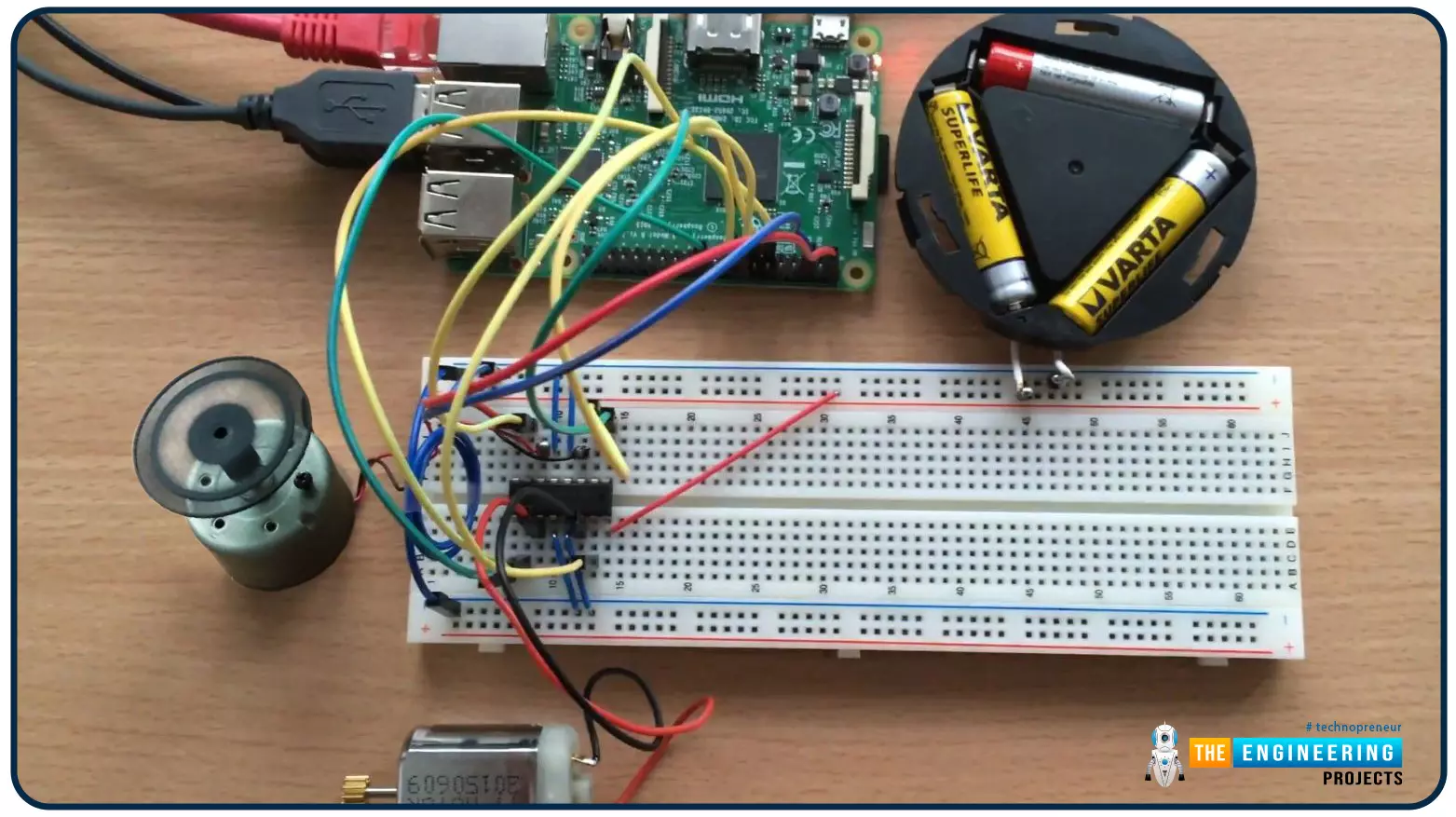
Hello friends, I hope you all are doing well. Welcome to the 9th tutorial of our Raspberry Pi programming course. In the last chapter, we generated a PWM signal from our Raspberry Pi to control the brightness of an LED. We also studied different functions used in Python to perform PWM. In this chapter, we'll get a bit advanced with PWM and use it to control the speed and direction of a DC motor with the help of a motor driver IC.

To control the speed & direction of the DC Motor, we will:

  • Design a Circuit Diagram.
  • Write Python code.

Components Required

We will use the following components to control the DC motor speed:

  • Raspberry Pi 4.
  • DC Motor.
  • Motor driver IC(L293D).
  • Breadboard.
  • Jumper wires.

Controlling DC Motor speed with Raspberry Pi 4

  • In order to control the DC motor with any microcontroller, we need to use the motor drivers i.e. L298, ULN2003 etc.
  • In our project, DC motors are controlled by the L293D motor driver, an intermediate integrated circuit.
  • Raspberry Pi 4 will send the signal to the motor driver, which in turn will control the speed or direction of the DC motor.
  • To regulate the DC motor's speed, we will write Python programs in Raspberry Pi, to control the GPIO pins and will send signals to the motor driver IC.

Control DC motor using PWM

Pulse Width Modulation(we studied in the previous tutorial) will be used to regulate the speed of a DC motor. A quick recall, a  PWM signal is used to generate a variable voltage at the output depending on the duty cycle. The duty cycle refers to the length of time during which the signal is kept at a high level and determines how much power is given to the signal.

As a result of the PWM signal, the speed of a DC motor can be controlled in a non-resistive or non-dissipative manner.


Motor Driver L293D

  • We will use the L293D Motor driver, it will get the signals from Raspberry Pi through its GPIO pins and will control the motor.
  • The Raspberry Pi's low-current signal is amplified by this motor driver into a high-current signal used to drive a motor.

L293D Pinout

The L293D pinout is shown in the following diagram.

  • As you can see in the L293D pinout, it has 4 input/output channels.
  • In order to control the speed of 1 DC motor, we need to use 2 channels of L293D.
  • So, a single L293D IC can control 2 DC motors at a time.
  • It also has 2 Enable Pins and are used as master control pins for these channels.
  • Enable Pin 1 is used to control the first two channels(left side), while Enable Pin 9 is used to control the last two channels(right side).
  • Vss(Pin16) is the reference voltage pin, it should be provided with 3.3V or 5V. It's the reference to the signals provided at Input pins. In our case, we are using RPi4 and its GPIO pins provide 3.3V, so we will give 3.3V at Vss pin.
  • Vs(Pin8) is the source voltage pin, normally a 9V or 12V power is applied at this pin. The voltage at Vs pin is provided to all the output pins by the L293D.

Why do we need a Motor Driver L293D?

The microcontrollers provide either 5V or 3.3V at their GPIO Pins, in the case of RPi4, it's 3.3V. The current rating of these GPIO pins is normally 10-50mA, which is quite low and it's justifiable as their sole purpose is to send the signal.

Now if we talk about DC Motors, they normally operate at 5V-48V and have a current rating from 100mA to 10A. So, we can't connect a DC motor directly to a microcontroller's pin. We need a motor driver to amplify the voltage and current.

Moreover, DC motors also produce back EMF, which may burn the GPIO, so in order to protect the board, we should have a motor driver in between.

L293D Working

  • The PWM signal generated by the Raspberry Pi will be provided to Input1 and Input2.
  • If Input1 is at a High state, while Input2 is at a LOW state, the motor will rotate in one direction, let's say clockwise.
  • If we changed the states i.e. Input1 at a LOW state, while Input2 at a HIGH state, the motor will change its direction and will rotate in the anti-clockwise direction.
  • The motor won't run if you simultaneously supply highs or lows to both inputs.

Controlling DC Motor with Raspberry Pi4

  • As shown in the above figure, we will use three GPIO pins of Raspberry Pi 4, connected to Enable1, Input1 and Input2 of the L293D motor driver.
  • Vss Pin of L293D is provided with 3.3V from RPi4.
  • We will also connect the GND of L293D with that of RPI4(Pin6).
  • Vss of L293D is provided with +9V from the battery and that will be provided at the output and will control the motor's speed.

Python Code for DC Motor Speed Control

We have designed the circuit in the above section and now it's time to get our hands on Python code. We will be using the Thonny IDE in Raspberry Pi 4.

In this code, we will write a simple code to drive the motor forward for 5 seconds, then backward for another 5 seconds at a 50% duty cycle. You can alter any of these values as you see fit.

I will explain the code line by line for better understanding:

  • To use the GPIO pins, you must first import the GPIO module using the import command.

  • We also need to include a sleep instruction, required while making changes to the PWM duty cycle or the direction of the motors.

  • To access the GPIO pins, you'll first need to put them into board mode. To do so, run this command.

  • As we need to send PWM signals to the motor driver, so we need to make these pins OUTPUT, using the below command:

  • Let's create a PWM object by using the PWM GPIO pin, using the below command:

  • LEt's start the PWM object with a 0% duty cycle.

  • Initiating a clockwise movement of the motor by making the first pin HIGH and the second one LOW.

  • Setting the 25% duty cycle to the PWM object:

  • Setting the Enable Pin HIGH:

  • Delay of 5 seconds:

  • Enable Pin is set to LOW to stop the motor.

  • Reverse the motor's polarity:

  • By setting the duty cycle to 50%, the motor will now run at 50% speed in the opposite direction.

  • The enable pin should be set to HIGH.

  • Keep the code running for another five seconds:

  • Reset the Enable pin to turn off the motor.

  • After that, clean up and reset the GPIO channels after disabling the PWM object. It's always recommended to clean up the GPIO pins so that the next program could use them without getting an error, saying the pin you selected is not available to use.

  • If you followed all of the steps correctly, your engine will run for five seconds in the forward direction and then for five seconds in the reverse direction.

  • A variable whose value changes with each iteration of the loop is called an iterative variable. You may adjust the duty cycle such that your motor's speed grows in steps as you observe it.

  • Now as we lowered the duty cycle to 25%, the DC motor speed gets lowered as well.

  • Here's the complete code and the hardware images:

Application of DC motor control systems

DC Series Motor:

Motors from the DC series are commonly employed in electric locomotives and fast transit systems, as well as trolley vehicles. Because of their high starting torque, they're also found in cranes, hoists, and conveyors.

DC Shunt motor:

The use of DC shunt motors in rolling mills is due to their ability to accurately manage speed. They're used for driving lathes at a fixed speed, used in reciprocating and centrifugal pump drives, and also used in blowers, machines, and reciprocating pumps.

Synchronous Motors:

They can be found in a wide variety of machinery, including elevators, conveyors, heavy planers, shears, and punches, as well as intermittently high torque loads and air compressors.

Conclusion

Congratulations! You have made it to the end of this tutorial. We have seen how PWM is used with a motor driver IC to control a DC motor's speed and direction. In the next tutorial, we will have a look at how to Control a Stepper Motor with Raspberry Pi 4 using Python. Till then, take care. Have fun !!!

Create PWM Signal in Raspberry Pi 4 using Python

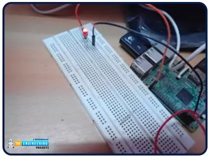
Hello friends, I hope you all are doing great. It's the 8th tutorial in our Raspberry Pi programming course. In the previous lectures, we interfaced LCD 16x2 and Keypad 4x4 with Raspberry Pi 4. In this chapter, we are not going to interface any external module with Pi, instead, we'll create a PWM signal in the raspberry pi using Python. Let's get started:

Components Required

We are going to use the below components in today's PWM project:

  1. Raspberry Pi 4.
  2. LED.
  3. A resistor of 330 ohms.
  4. Breadboard.
  5. Jumper wires.

Before going forward, let's first understand what is PWM:

What is PWM?

  • In PWM(Pulse Width Modulation), we simply turn on and off our power supply at regular intervals and thus reduce the average power of the signal.
  • We have shared a detailed tutorial on Introduction to PWM(Pulse Width Modulation), you should read it once to understand PWM.

Let's understand the working of PWM with an LED example. We can change the brightness of an LED using PWM. If we provide +5V, the LED will have full brightness, but if we provide +2.5V to the LED, its brightness will fade. We achieve +2.5V from a +5V signal by turning it ON and OFF continually. So, in a signal of 1 sec, if we turn it ON and OFF 100 times, the overall power of the signal will be halved as it's in an OFF state for 50% of the duration. This process is called Pulse Width Modulation(PWM).

What is a "duty cycle"?

The percentage for which the signal remains in the ON state during one cycle is called the duty cycle.

To get an ideal square wave, you need a duty cycle of 50%. The signal is always on(full-scale) with a 100% duty cycle, while the signal is always off(Ground) with a 0% duty cycle.

PWM Signal's Frequency

The inverse of the period is the frequency of the signal, which is the number of times a periodic change is accomplished per unit of time. Speed is determined by how quickly a signal goes from high to low i.e. how quickly a PWM completes a cycle. Constant voltage output is achieved by continually turning the digital signal on and off at a high frequency.

PWM Resolution

The 'PWM resolution' refers to the degree of control over the duty cycle. The more 'brightness' levels we can display, the greater our PWM resolution needs to be. Pprecise microcontroller timing is required because the duty cycle is normally around 50Hz. The more powerful the microcontroller, the shorter the time intervals it can keep track of. The microcontroller must not only time the 'interrupt,' which generates the pulse but also run the code that controls the LED output, which must be completed before the next interrupt is called, which is another limiting issue. It's also likely that you'll want your microcontroller to accomplish activities other than controlling the brightness of the LEDs, so you'll need some spare execution time between interrupts.

The fundamental benefit of greater PWM resolutions for LED PWM control is that it reduces the difference between 'off' and the LED's lowest achievable brightness. Suppose we have a duty cycle of 20,000 microseconds and a resolution of 10,000 microseconds. In that case, the difference in brightness between "off" and the lowest possible brightness will be 50 percent of the total brightness. The difference would be 10% at a resolution of 2,000 microseconds. The "PWM resolution" determines the number of brightness levels that we can support between 0% and 100% when it comes to brightness levels. (100 percent). Again, the better the resolution, the more precise the timing, and the more computing power is needed to process the information.

The above diagram shows a PWM resolution of 10%.

Depending on the nature of your application, the resolution and overall duty cycle requirements may be different. There is no need for precision control for simple displays; nevertheless, the ability to manage the brightness level may be crucial (think of the issue of mixing colors using an RGB LED, for example). More control and accuracy necessitate more microcontroller resources; thus, the trade-off is straightforward.

Applications of PWM

  1. Using PWM, you may adjust the screen's brightness.
  2. Use a variety of loudness levels for the buzzer.
  3. Control the motor's speed i.e. DC, Servo, Stepper etc.
  4. Provide a physical outlet for analog signals.
  5. Create an audio output.
  6. Communication: encoding of the message.

Raspberry Pi PWM Signal

  • Raspberry Pi 4 has two PWM channels, PWM0 and PWM1.
  • Four PWM pins are available on the Raspberry Pi, GPIO12 and GPIO18 share the PWM0 channel, whereas GPIO13 and GPIO19 share the PWM1 channel.
  • The following are the pinouts for the PWM channels on the 40-pin header:

  • The Raspberry Pi 40-pin Header's PWM pins are illustrated in the following figure.

  • On a Raspberry Pi, all of the PWM pins are used by the audio subsystem. As a result, we can choose either PWM or Audio output.
  • Hardware PWM signals can only be generated by importing the Pigpio library. The RPi.GPIO library, on the other hand, can be used to generate PWM signals.

Software PWM in Raspberry Pi

  • There are two ways to generate PWM signals with the Raspberry Pi i.e. hardware PWM and software PWM.
  • It is possible to use all 26 GPIO pins on the RPi to generate PWM frequencies of up to a few thousand Hertz using software PWM. The software PWM signals' duty cycle can be adjusted anywhere from 0% to 100%.
  • Software PWM is more adaptable than hardware PWM. However, software-based PWM has the major disadvantage of being less accurate than a hardware-based PWM channel. Because software PWM generation consumes CPU resources, your Raspberry PI's processing capacity will be limited.

Raspberry Pi PWM Circuit Diagram

Even though hardware PWM is the preferred approach for generating PWM from the Raspberry Pi, we will use software PWM in this article.

  • Connect the anode of the LED with GPIO21. After that, connect the LED's cathode to a 330 Ohm series resistor and ground the resistor's other end.
  • Pins 2 and 6 of the Pi board can be used to supply the circuit with Vcc and ground.

Python Code for PWM Signal Generation

The thorny Python IDE on raspberry pi will be used here to write our Python script. If you haven't already done so, please go back to Chapter 4 and read about how to get started with this IDE before reading on.

To keep things simple, we'll create a file called PMW.py and save it to our desktop.

Putting the project into action

We're using a 50 Hz software PWM signal to generate a customized sine wave with RPi. It has a 20-millisecond window at this frequency. During the application, the frequency does not fluctuate.

Increasing the software PWM duty cycle from 0 to 100 is required to produce a rectified sine wave. The PWM signal is applied to the LED in five-pulse trains every 0.1 seconds, with each train lasting 0.1 seconds.

As a result, the duty cycle is lowered from 100 to 1 in steps of minus one. Five PWM pulse trains, each lasting 0.1 seconds, are applied to each increment. Iteration continues indefinitely until a keyboard interrupt is received, at which point the user program terminates.

Code

Import RPi.GPIO then time libraries. Then a simple script is run to begin. The GPIO.setwarnings() method is used to disable the warnings.

To set the RPi's PINs to the number of board, use the GPIO.setmode() function to set the pin numbering. The GPIO.setup() method configures pin 40 of the board as an output. However, the GPIO.PWM() technique is used to instantiate board pin 40 as a software PWM.

It is possible to write a user-defined setup() function to ensure that the software PWM has no duty cycle when it is first started. Only one instance of this function is ever called.

The duty cycle of the PWM signal is altered from 0 to 100 and then back to 0 in a user-defined loop() function. This occurs in increments of one, with a 0.1-second gap between each. For an endless number of times, the LED lights up and fades back down.

The PWM signal is turned off when a keyboard interrupt is received by calling the endprogram() method. The GPIO of the Raspberry Pi is then wiped clean.

Setup() and loop() are the two methods in a try-exception statement, and they are each called once.

Code Syntax

The GPIO.PWM() method

A PWM instance can be created with the help of this function. This is a two-step process:

  • PWM signal must be generated on a specific channel number
  • The frequency in Hertz of the PWM signal. The method must be assigned to a variable before an instance can be generated.

The syntax for this method is:

The number of the channel must be given in accordance with the user-Board program or BCM numbering.

The start() method

This technique can be used with a PWM software instance. PWM duty cycle is all you need to know about this.

PWM instances can be accessed by calling this method from a Python program. A software PWM signal with the specified duty cycle is started at the supplied channel.

The syntax is as follows:

The ChangeFrequency() method

This technique can be used with a PWM software instance. There's only one thing needed: a new Hertz value for the PWM signal's frequency.

The frequency of the PWM output is changed when this method is used on a PWM object in Python.

The syntax is as follows:

The ChangeDutyCycle() method

An instance of PWM software can use this technique. One reason is all that is required: the launch of a new cycle of service.

The duty cycle ranges from 0.0 to 100.0. The duty cycle of the PWM signal is changed when this method is called on a PWM instance in Python.

Here is the syntax of the method:

The stop() method

This technique can be used with a software PWM instance. It doesn't need a response. An instance's PWM signal is paused when this method is called on it.

The syntax for this method is:

Output

Conclusion

Congratulations! You have made it to the end of this tutorial. We have seen how PWM is generated in the raspberry pi. We have also seen how to set up our raspberry pi pins with LEDs to be controlled and wrote a python program that controls the output of these pins. The following tutorial will learn how to control a DC motor with Raspberry Pi 4 using Python.

How to Control Raspberry Pi 4 from Laptop using VNC

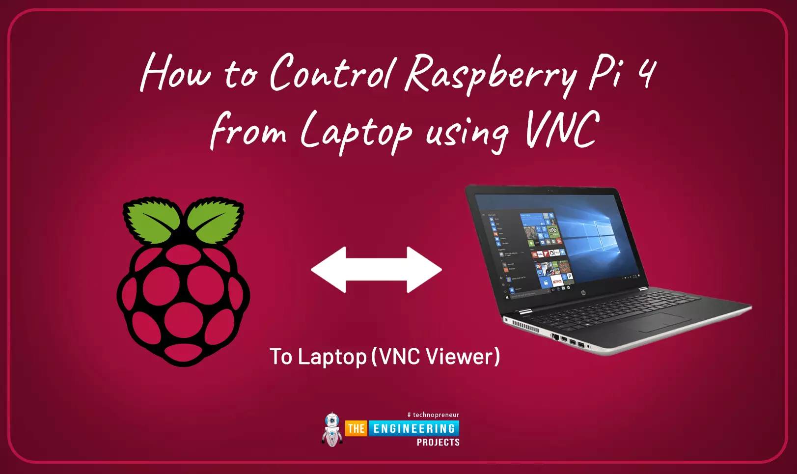
This is the third tutorial in our Raspberry Pi programming course. In the previous chapter, we learned how to install Raspbian on our Raspberry Pi mini-computer. In this chapter, we'll learn how to use a VNC server to remotely control and see its desktop from our computer.

Where To Buy?
No.ComponentsDistributorLink To Buy
1Raspberry Pi 4AmazonBuy Now

What is VNC?

Computing over a network is known as "virtual network computing," or "VNC." To remotely control another computer, you can use this screen-sharing technology, which works on all major operating systems. As a result, a remote user can interact with a computer's display (screen, keyboard, and mouse) as if they were sitting right in front of it.

VNC takes advantage of the client/server concept. Rather than installing a VNC server on the distant device, users will instead use a VNC viewer or client on the device they wish to control. Use a tablet or a smartphone in place of one of the previously mentioned computers. As soon as a viewer and a server are connected, the server gives the viewer a screen copy of the computer on the other side of the world.

Thanks to the application, both the remote user and the connected user can see and control everything on the distant computer's screen using keyboard and mouse instructions from afar.

What’s a VNC Server?

Other programs (referred to as "clients") can access the resources on a computer server. The server can provide services to one or more clients, such as data or resource sharing, in what is known as the "client-server model." The advantage of this strategy is that a single server can service many clients, while a single client can make use of several servers. A server will respond to a request from a client by sending back a response.

When a computer has VNC Server software installed, it can be accessed and controlled remotely from another device. The software makes it possible to stream the device's desktop to another computer running VNC Viewer. Once a connection is established, users using VNC Viewer can view exactly what a person seated in front of the remote computer sees (with permission).

What’s a VNC Viewer?

A viewer is a piece of software that allows you to see the contents of a digital file in its entirety.

Remote control of local PCs and mobile devices is made possible through the usage of VNC Viewer. Using VNC Viewer software, a user can access and operate a machine from another place using a device such as a computer, tablet, or smartphone.

As a desktop sharing system, it delivers keystrokes, mouse clicks, and other input events to a remote computer running VNC Server so that you may control it from your mobile device once connected. It's as if you're sitting directly in front of the computer that you've accessed remotely.

What protocol is used by VNC?

VNC uses a protocol called remote framebuffer to share data between the client and server, which determines the type of data exchanged. Using this, clients can access and control another machine from afar. Because it's compatible with all windowing apps and systems, it may be used on any mainstream operating system, including Windows, macOS, Linux, and others.

User access to a computer's monitor, mouse and keyboard is provided via the RFB client or viewer (also known as a client). Framebuffer updates originate on the RFB server (as in the windowing system). A key goal of Remote Framebuffer is to run on a wide range of hardware and to simplify the process of building a client by requiring as little input from the client as possible.

File transmission, more advanced compression, and stricter security procedures have all been added to RFB since its inception as a basic protocol. When using VNC, clients and servers can agree on the appropriate RFB version to use, as well as the security and compression options that are supported by both parties. Cross-platform interoperability is made possible as a result of this.

Why use VNC?

There are times when you won't be able to use your Raspberry Pi. For instance, you might have forgotten about your Raspberry Pi while away, or it may be buried beneath your TV or other devices. Using Raspbian and the free VNC software, you can connect to your Raspberry Pi wirelessly from any other device running Raspbian. You have the option of connecting to the internet or to your home network.

Prerequisites

  • Raspberry Pi running Raspbian
  • A network connection
  • A VNC server and viewer

Configuring VNC on a local network

Enable VNC

Begin by ensuring that both computers involved are on the same local network.

Select Preferences > Raspberry Pi Configuration from the apps menu icon (raspberry) at the top-left of the screen.

The default password for Raspbian is 'raspberry,' which you should change right away. By clicking the Change Password option, you can set a new password. Select the Enabled radio button next to VNC on the Interfaces tab. OK when you're finished. Menu bar in upper right corner of screen has VNC button at end of menu bar VNC Server will be launched as soon as you click on it.

Note your Ip address for the next steps.

Open VNC Viewer

You can now link your Raspberry Pi to another computer. Instead of a Windows computer, you might use a Mac or Linux computer on the same network or even another Raspberry Pi.

With a web-based interface, VNC Viewer may be used on a variety of platforms including macOS, Linux, Android, and iOS. On the official website of realvnc, download VNC Viewer. To use the software, it must first be downloaded and then installed.

Connect to Raspberry Pi

In the "Enter a VNC Server address or search" box of the VNC Viewer, enter the Raspberry Pi's IP address (the four numbers displayed in VNC Server). RETURN is all that is needed to disconnect when a connection is established. If an error message appears, press the Enter key to proceed.

For security reasons, you'll need to log in with your Raspberry Pi's username and password. To remember your password and access Raspbian, select ‘Forgot Password’ and then OK.

Remote control

The Raspberry Pi window is shown on your windows computer. By dragging the mouse cursor around the screen, you can see the Raspberry Pi's mouse. Remote control of your Raspberry Pi is now possible thanks to this window.

When you hover your mouse over the top of the VNC Viewer window, a menu will appear. Enter The Full Screen option is located to the left of the Options and allows you to have the preview window take over your screen. Because your Raspberry Pi display may not be compatible with your PC display, choose Scale from the menu (such that it is set to Scale Automatically).

Your Raspberry Pi will provide you a desktop PC-like experience.

Looking at properties

Close the VNC preview window and use the VNC Connect menu bar to get to the properties. You can end a session from the drop-down menu.

To access your Raspberry Pi's desktop, simply open VNC Viewer from the Address Book. To reopen the connection, simply double-click on the icon and select Properties from the context menu that appears.

Enter 'Raspberry Pi' in the Name field. This will give your screen a more personal touch. After that, select Options. Automatic is the default setting for Picture Quality on your camera. The lower the setting, the better; if you have a fast connection, the higher it should be.

Make sure to check out the "Experts" section at the bottom. In this section, you'll find configuration options for pretty about everything on your computer. You can change the False to True option in the Fullscreen drop down box. In VNC Viewer, you can preview your Raspberry Pi in full-screen mode. After you've made your options, click OK to keep them.

Remote access in wide area network

You may access your Raspberry Pi from anywhere in the world with a RealVNC account.

Verify your identity in the upper left corner of VNC Viewer when it has been opened. Sign up if you don’t have an account. Set up a password for your account. Keep your password at least eight characters long and difficult to decipher. There is a RealVNC home page that you will be taken to. Verify your email address and you're done setting up.

Sign in

A single account must now be used to sign in to both of these applications.

You should be able to see the VNC Viewer Sign In window from the computer. Your Raspberry Pi must be running VNC Server before you can connect to the cloud.

Go back to the VNC Viewer application on your PC. In the Address Book area, you will find a Raspberry Pi Window, but you'll also notice a Team option immediately below it.

What exactly is the distinction between the two?

This account can be used from different networks and operates remotely.

Send files

Sending and receiving files is possible between the Pi and computer. We've created a new text file called test.txt in our Documents folder.

Connect to the Pi using VNC Viewer to send a file. An option to transfer files can be found in the VNC Viewer preview window's menu.

Sending files is as simple as clicking the Send Files button in the VNC Viewer's File Transfer window and the transfer will begin. Click Open after you've selected a file from your computer's file picker. On your Raspberry Pi's desktop, the file will be saved. The message "Download complete" will appear in the File Transfer window; close it.

Retrieve files

With VNC Viewer, it is possible to download files from your Raspberry Pi's SD card. VNC Server icon can be found in the Raspbian menu bar by right-clicking it. Select File Transfer from the VNC Server drop-down option to open the File Transfer window.

Your Raspberry Pi can now be accessed remotely. The screen and keyboard can now be removed from your Raspberry Pi and left connected to the network. The PC connection will be waiting for you when you're ready.

Connect with Android and iOS

Using your smartphone, you can also remotely connect to the Raspberry Pi. Download the VNC Viewer software from the app store, then, open your VNC Connect account and log in using your email address and password.

Your Raspberry Pi will be listed in the Team drop-down menu. Click it and input your Raspberry Pi's username and password.

On start up, you will have to go through the 'Control the computer' step. The 'How to control' window will open once you click Next. This screen shows you how to use movements like mouse clicks on the touchscreen. Start using Raspberry Pi from your phone by closing this window.

To move the cursor, make use of your smartphone's touchscreen. An on-screen keyboard can be accessed with a simple swipe of your finger on a key at the top of the app.

Even on your phone, you can now access your Raspberry Pi. Remote monitoring has never been easier.

Misconceptions about VNC and VNC Connect

When it comes to deploying new software and systems, there will always be some trepidation, and there is a lot of misinformation floating about that influences how people feel about doing so. However, this has the drawback of preventing individuals and organizations from reaping the full benefits of new technologies.

In this article, we'll debunk some of the most popular myths regarding VNC Connect, many of which can be traced back to VNC's open-source roots.

  1. VNC is open source. Open-source software is common among recent adaptations of the VNC protocol; however, this does not apply to all VNC-based software. As of 2016, VNC Connect, which uses RFB protocol version 6, is not open source.
  2. It is not safe to use VNC-based software. Out of the box, open source VNC-based remote access is vulnerable to attack. Secure connections are built into VNC Connect right out of the box, and remote PCs are secured by default with a password or system login credentials.
  3. VNC doesn't work with the cloud. The majority of open-source VNC-based applications is only available for use offline. Offline (commonly known as "direct") and cloud connections are also available through VNC connect, so you can select the one that best suits your company needs.
  4. The VNC protocol is out of date. VNC technology has been around for more than 20 years, but it has undergone a major transformation. VNC Connect is continually checked and updated to correct any faults that may arise and to meet the ever-changing needs of its users. The software roadmap is based on user feedback to ensure that it incorporates the designs and features that are most frequently requested.

Conclusion

Because buying two keyboards, monitors, and mice for your computer and Raspberry Pi would be prohibitively expensive, VNC is a great option to gain access to your raspberry pi remotely. The two computers can be used at the same time, and you don't have to switch between them. So far, we've learned how to set up our mini-computer for VNC and how to establish a remote connection to the VNC viewer. Our first project will be to use Python to control the GPIO pins of a Raspberry Pi 4, which we will cover in the next topic.

Installation of Raspbian in Raspberry Pi 4

Welcome to the second chapter of our beginner's course on the Raspberry Pi. In the previous tutorial, we learned about the components of this little computer. We also considered its uses, as well as the most important advantages and disadvantages. Let's get started with setting up our little computer to run the Raspbian operating system in this lesson.

Where To Buy?
No.ComponentsDistributorLink To Buy
1Raspberry Pi 4AmazonBuy Now

How to Install Raspbian using an imager

The next step is to make sure you have your board and SD card. The Raspberry Pi has an operating system because it is a full computer. For those who prefer a GUI desktop experience, a headless mode is still an option. Most people use Raspbian, a Debian-based operating system tailored specifically for the Raspberry Pi. However, there are other options. An excellent starting point is this operating system, which is likely to support other Linux packages that you are already familiar with.

Other means to install and run an operating system on the Raspberry Pi are also available. The imager installer is the most convenient method. As long as you're familiar with the operating system ISO, you may download it to your SD card, format your SD card and mount the ISO, and then boot the Pi. Follow the imager installation option if that's all gibberish to you.

Download imager

For this process, we will open our browser and navigate to the raspberry pi website and down to the software option, you will see a download for windows. This button allows you to download the imager for windows which in my case I am using. If you are using another operating system like mac and ubuntu there are also imagers for those particular operating systems.

The executable imager file will be downloaded to your computer as seen below.

This software allows us to flash our operating system into the micro-SD card which will be used in the mini-computer.

Flashing the operating system into the storage card

Connect the card reader with an sd card in it to your computer through USB or a regular card slot.

Launch the imager

On your computer, navigate to the location you downloaded the imager software and run it. In windows just double-click on it and it should startup.

Once the installation is done, go ahead and run the application:

Selecting the SD card

On the pi imager window, there are two options and when we click the choose storage, our SD card is detected since we plugged it into our pc.

If you have any other drive plugged into your pc, they will also appear on the window therefore be careful to select the right one otherwise you will override the wrong drive and lose your saved files.

Select the operating system

We will click on the other button "choose os" that is on the pi imager window to select the operating system we want to flash into our SD card. You will see different types of operating systems available for installation and we will go ahead and select the 32-bit raspberry pi os.

Write to SD card

Once all the required parameters are set, i.e., the os and storage, go ahead and click the write button. The flashing process begins and it takes a minimum of 5 minutes to complete.

How to Install Raspbian with etcher

NOOBS (New Out of the Box Software) is an automated installer provided by the Pi Foundation, but for this article, we're going to forego it for now.

To complete numerous projects, it is a good idea for you to learn about "flashing" the SD card yourself. Despite NOOBS's reputation as a beginner's tool, I found this one to be easier to use.

You'll need an image file and an application to put it to your SD card to install an operating system. However, you can use any operating system of your choice for this guide. For example LibreELEC for a media box; RetroPie for retro gaming; and so on.

Because it's accessible for Windows, macOS, and Linux, Etcher is my go-to tool for writing to the SD card. There may be partitions that aren't visible in Windows, but these may be cleaned out with diskpart if you've previously used the SD card in a Pi.)

The full Raspbian image with suggested software is what I'm running, so go ahead and download it if that's what your Pi model calls for. It will either be an IMG file or an IMG compressed into a ZIP file (which you don't have to do if you're using Etcher).

It's as simple as opening Etcher and clicking the Select Image button to select your downloaded file. Flash your SD card by selecting it as the target. Selecting a destination drive should only be done with extreme caution, as the operation will wipe whatever disk you select.

Once the SD card has been ejected, you can insert it into your Pi, connect the HDMI wire to a display or TV, and turn on the Pi by plugging it into the wall. Once you've landed on the Raspbian desktop, you can begin fiddling with your Wi-Fi and software installations with apt.

Booting the raspberry pi

Now that flashing is complete, with the pi powered off, we will go ahead and eject the storage SD from the pc and put it back to the raspberry pi SD slot. Then we will go ahead and plug the power cord back in and our mini computer should start. If you mouse, keyboard and screen go ahead in the previous tutorial and see how they are connected since they are necessary for this step.

The mini-computer boots up into the os and you will find a window with instructions on what to do. Follow through the graphical user interface, provide a password, location, screen, and Wi-Fi connection.

Then go ahead and install updates and the raspberry pi will reboot. A couple of issues will be solved when it boots up such as window dimensions and resolution.

We will do some more configurations in the terminal, therefore go ahead and start the terminal.

Configuration

Preferences on the menu can be found in the Configuration tool, which enables you to change most of your Pi's settings, including the password.

Several options are available, as illustrated in the screenshots below. We'll enable vnc and ssh for the time being. The Raspberry Pi's fundamental system settings can be modified in this area.

It's a good idea to change the factory default "raspberry" password for the pi user. When your Raspberry Pi boots up, choose between using Desktop or CLI (command line interface), and enable Auto Login.

You can set your Raspberry Pi to wait until a network connection is available before starting up, by selecting network at boot.

You can choose whether or not your Raspberry Pi boots up with a splash screen.

Interfaces

There are numerous ways to connect your Raspberry Pi to other devices and components. For your Raspberry Pi to recognize that a specific type of connection has been made to it, you must use the Interfaces tab to enable or disable the various connections.

To use the camera on the Raspberry Pi, you must first enable it.

A Raspberry Pi can be accessed remotely through SSH or VNC.

To enable the SPI, I2C, and Serial (Rx, Tx) GPIO pins, go to the SPI menu. To enable the 1-Wire GPIO pins, go to the 1-Wire menu. To enable the 1-Wire GPIO pin, go to the 1-Wire menu. To enable Remote GPIO, go to the Remote GPIO menu.

Performance

We can alter the performance settings of our Raspberry Pi on this tab if we need to do so for any specific project.

Caution: Changing the performance parameters on your Raspberry Pi could cause it to behave strangely or stop working altogether.

If you want to boost your computer's performance, you can overclock the CPU and adjust its voltage.

Localization

This enables you to customize your Raspberry Pi's settings based on where you live.

To configure your Raspberry Pi's locale, select the language, nation, and character set you want to use.

For example, you may want to change your time zone, or you may want to switch to a different type of keyboard layout.

Go ahead and finalize the configuration and reboot now that you've completed the setup.

Setting up remote connections

  1. On Windows, connecting to the Raspberry Pi via RDP is a straightforward process.

You don't need much more than a remote desktop program and the IP address of your Raspberry Pi to get started.

Open Remote Desktop Connection on your Windows computer to get started. The app will appear as seen in the image below.

In the "Computer:" field, type in the local IP address of your Raspberry Pi (1.), and then click the "Connect" button (2.).

  1. After connecting to your Raspberry Pi, the xrdp software will present you with this screen.

Enter the account's "username" and "password" from your Raspberry Pi.

If you're logging in as the default pi user, your username and password should be "pi" and "raspberry," respectively.

  1. You should now be able to connect to your Raspberry Pi using the Windows remote desktop program.

Have trouble connecting to the Raspberry Pi? Double-check that your IP address is accurate. TeamViewer or TightVNC are two other options.

I hope you can now access the Raspberry Pi's remote desktop using the tool of your choice.

Installing Python on the Raspberry Pi

Python will be installed on your Raspberry Pi, and you'll see how simple it is to do so. This can be accomplished in a few simple steps thanks to Python's default package repository.

  • We should check our package list and existing packages for updates before we install Python. The following instructions can be used to update both of these on your device. Let's go on to the next phase now that we've completed this one.
  • Next, we'll set up our Raspberry Pi with the Python package we downloaded earlier. Python 3 will be the focus of this guide because it is the most recent version that is still widely supported. Installing Python is as simple as running the following command.
  • Once this process completes, you will now have Python installed on your Raspberry Pi. This will provide you with the minimal essentials of Python, but that is all you will need for now. Later on, you will end up using package management such as pip to extend the capabilities of Python.

Using the Thorny Desktop IDE

Thonny, a Python IDE, is pre-installed on desktop versions of Raspberry Pi OS. It is much easier, faster, and more pleasant to write code when using an IDE. Open Thonny on your Raspberry Pi, and then learn a little bit of Python in the process.

  • The Thonny IDE must first be opened before we can proceed. On your computer's desktop, go to Start, and then click "Raspberry". Next, you'll need to click on the "Programming" option on the left-hand side of the page. Lastly, select the "Thonny Python IDE" option to launch the Python editor on your Raspberry Pi".
  • Since you're probably using Thonny for the first time, let's go through the basics of how it works.

The toolbar is located at the very top of the screen. All the buttons you'll ever need to work with the editor are right here. The "Save" and "Run" buttons are the only ones you'll need (1.)

It's time for the center box. All of your Python code can be written here. (2.)

Finally, the Python shell is at the bottom. You can use this to directly communicate with Python. The output of your code can also be found here (3.).

Conclusion

You should now have a better understanding of how to get started with Python on your Raspberry Pi. This instruction explains how to install the Raspbian operating system, configure its interface, and install the Python interpreter with a few basic command lines. On the Raspberry Pi, we also demonstrated how to start a Python code editor to develop code.

Getting Started with Raspberry Pi Programming Series

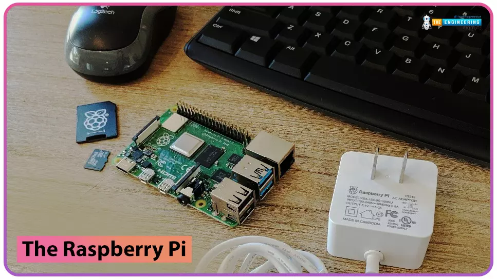
to our new beginner’s course on Raspberry Pi. This course is appropriate for anyone using either a traditional Raspberry Pi board or the new Raspberry Pi 400 board that includes an integrated keyboard and display. Learning how to code, building robots, and doing plenty of other strange and exciting things are all possible with this low-cost computer setup. The Raspberry Pi can do everything a computer can do, from surfing the web to viewing movies and music, and playing video games.

Raspberry Pi is much more than a modern computer. It`s created to educate young people on how to program in languages such as Scratch and Python, and it comes with all of the major programming languages pre-installed. The world is in desperate need of programmers now more than ever, and Raspberry Pi has sparked a new generation's interest in computer science and technology. Raspberry Pi is used by people of all ages to build intriguing projects ranging from old-school gaming systems to internet-connected weather equipment.

Where To Buy?
No.ComponentsDistributorLink To Buy
1Raspberry Pi 4AmazonBuy Now

What are the aims of this course?

In this course, we'll learn how to make games, build robots, or hack all kinds of fantastic projects. The Raspberry Pi 4 Model B will be covered in this course. In the event that you're working with a different model of Raspberry Pi, don't be worried. whatever is taught here can be applied to any other model in the family.

What is this mini-computer?

It is a small computer about the size of a credit card that can run the Linux operating system. It uses a "system on a chip," which combines the CPU, GPU, RAM, USB ports, and other components into a single chip.

To distinguish it from traditional computers that conceal their internal components behind a casing, the Raspberry Pi's ports and functions are fully exposed, a protective case is available to buy. If you want to know how different computer components work and where to put the various peripherals, this is a great resource.

Features

All Raspberry Pi models share one feature in common:

  • Software written for one model can be used on another, as they are interchangeable.
  • Raspberry Pi operating system can even run on a pre-release Model B prototype. Although it will take longer, still run.

With this, what are you able to accomplish?

Now you've got a little machine that runs a lot of free software, so that's good. Exactly what can you do with it? Fortunately, I've got a simple and fun Python project that I used to teach middle school children in a coding lesson.

  • It's possible to create a weather station, a calculator, a gaming gadget, and a lot more out of the same thing. If you have a Raspberry Pi, you can even make a customized espresso machine that is secure like a Raspberry Pi locked door lock, as this one.
  • Can be used as a game server
  • Controller for robots
  • Webserver
  • Cryptocurrency Mining

Advantages of using this mini-computer

  • Low price
  • High computing power in a small board
  • Numerous interfaces
  • Linux and Python are supported

Disadvantages

  • Windows cannot be installed on the computer.
  • Inconvenient to use as a Desktop PC.
  • There is no graphics processor.
  • Internal eMMC storage is not present.
  • We can't attach external RAM as in a normal computer.

Components in a Raspberry pi

The Raspberry Pi features a number of parts that can be used to control the Raspberry Pi as well as other devices. The following ports will be available on your Raspberry Pi:

  1. System-on-chip

The majority of the Raspberry Pi's system resides on an integrated circuit, which is what the term "system-on-chip" refers to. Included in this is the CPU, which is referred to as a computer's 'brain,' as well as the graphics processing unit (GPU).

  1. Random-access memory (RAM)

A brain is useless without memory, therefore you'll notice another chip to the side of the SoC, tiny and black plastic, like a cube where RAM is located. When you're working on a Raspberry Pi, the RAM stores your work; it's only when you save it to the microSD card that it's written to the microSD card. The volatile and non-volatile memories of the Raspberry Pi are made up of these components. When the Raspberry Pi is turned off, the volatile RAM loses its contents, however, the non-volatile microSD card retains them.

  1. Raspberry pi`s radio module

A metallic lid covers the Raspberry Pi's radio component, which allows it to communicate wirelessly with other devices. In actuality, the radio has two main functions. Wi-Fi and Bluetooth are built-in, so you can use them to communicate with your computer and other nearby smart devices, sensors or cellphones.

  1. power management integrated circuit (PMIC)

Just behind the middle row of USB ports, an additional black, plastic-covered chip is seen towards the board's bottom border. The USB controller manages the four USB ports. The network controller is positioned next to this chip. An integrated circuit (PMIC) is also located on the upper left side of this board. It is in charge of converting power from a USB port to the precise voltage that the Raspberry Pi needs.

  1. Ports for connecting USB devices

The circuit board contains a variety of ports, beginning with four ports in the right side of the bottom edge. You can connect any USB-compatible device to your Raspberry Pi using these ports, including keyboards, mice, digital cameras, and flash drives. One of the two types of USB ports is a USB 2.0 port, which uses version two of the USB standard; the other is a USB 3.0 port, which uses version three.

  1. Ethernet port

There is an Ethernet port. Using an RJ45 cable, a Raspberry Pi can be linked with a wired computer network via this port. You'll notice two LEDs at the bottom, which indicate the connection is operational.

  1. Raspberry Pi AV jack

There is a 3.5 mm audio-visual jack. Connecting to amplified speakers rather than headphone jacks improves sound quality, but the headphone jack can still be used. Audio and video signals can be transmitted using the TRRS (tip-ring-ring-sleeve) adapter, which connects the 3.5 mm AV jack with projectors, tv, and other displays that can receive composite video signals.

  1. Camera connector

The camera serial interface (CSI), or camera connector, as it is most commonly called, is located above the AV jack and has a strange-looking plastic flap that may be pulled up (CSI). This allows you to connect a camera, which you'll learn later in this course.

  1. micro-HDMI ports

There are two micro HDMI connections available, which are a scaled-down version of the connectors seen on gaming consoles, set-top boxes, and televisions. Multimedia denotes that it can transport both audio and video information, and high-definition indicates that the quality will be excellent. A computer monitor, television, or projector will be needed to connect the Raspberry Pi to these adapters.

  1. Type-C port

The port above the HDMI ports is where you'll plug in the Raspberry Pi's power supply. USB Type-C ports can be found on smartphones, tablets, and other mobile devices. Instead of a standard mobile charger, employ the certified Raspberry Pi USB Type-C Power Supply for the best results.

  1. Display connector (DSI)

There is a strange-looking connector at the top of the board, which appears to be the camera connector at first sight, but it's not. It is for usage with a Raspberry Pi Touch Display.

  1. Raspberry Pi’s GPIO header

In two rows of 20 pins each, you'll find 40 metal pins along the right edge of the board. To communicate with peripherals such as LEDs and buttons to temperature sensors, joysticks, and pulse rate monitors, the Raspberry Pi includes a function known as GPIO (general-purpose input/output).

  1. Raspberry Pi’s microSD card connector

The Raspberry Pi has one more port, the micro-SD connector, which is on the other side of the circuit board. The MicroSD card is inserted here and you'll find all the files you've saved and installed as well as the operating system that makes your Raspberry Pi work.

What can you expect from the Raspberry Pi?

  • 1GB of RAM, and dual-band 802.11ac wireless LAN
  • This device has a Bluetooth 4.2 connection; it also has four USB 2.0 connections, an HDMI port, a composite video port, and 40 GPIO pins.
  • 3D graphics, Camera interface (CSI), Display interface, and Micro SD card slot (DSI)

What operating system is it using?

Unfortunately, the Raspberry Pi lacks the ability to run either Macintosh or Windows. Instead, it uses Raspbian, a Linux distribution. Installing Raspbian on your own micro-SD card is also possible using the NOOBS installation. You'll see this loading screen when you insert in the microSD card with Raspbian installed and turn on the Raspberry Pi.

As you've seen, the desktop on your huge PC looks exactly like the one you are used to. A web browser, terminal, picture viewer, calculator, and a slew of other tools are all included by default.

Requirements before you begin

The Raspberry Pi is the heart of your project, but without a power supply or storage, it won't be able to go very far. To get started, you'll need the following:

  1. The Raspberry Pi

      1. A Power Supply

The power supply standard for the Raspberry Pi 4 has been upgraded from microUSB to USB-C, which is an improvement. Powering your Raspberry Pi is best done with a dedicated power adapter from the Raspberry Pi Foundation.

      1. MicroSD Card

The later Pi models use microSD cards instead of the normal SD cards that were used in the original Pi models A and B. However, not all SD cards function correctly, therefore it's preferable to acquire a pre-loaded operating system with the original Raspberry Pi microSD card or a tested suitable card, such as the SanDisk Ultra 32GB.

      1. Case

This is technically optional, but we strongly advise it. It is a good idea to use a case to protect your bare board rather than leaving it exposed. The FLIRC case has a built-in heatsink, making it an excellent choice for older models of the Raspberry Pi.

      1. Mouse, Keyboard, and HDMI Cable

You can control your Raspberry Pi using a keyboard and a mouse. Raspberry Pi can utilize almost any USB-connected keyboard and mouse, wired or wireless. However, don`t use 'gaming' keyboards with flashing lights since they consume too much power to be used successfully.

USB gamepads are also necessary when you are building consoles like a gaming rig, therefore, don't forget about them.

First time set up

We are now going to set up our minicomputer therefore follow these simple steps to get yours up and running:

  • An SD card should be inserted into the SD card slot on the pi board. For the time being, we strongly advise you to stick with Raspbian until you are more comfortable with its features.
  • Use one of the USB ports to connect a mouse and a keyboard to the system. When using 'gaming' mice or other high-end equipment that requires software and drivers, it might waste power and place additional strain on the system. Just use 'plug-and-play' equipment to keep things easy and hassle-free.
  • Using the HDMI port, connect a monitor. Connect the monitor to a wall outlet, and then turn the power on and off as necessary. If you turn on the Raspberry Pi right now, nothing will happen. Adapters for non-HDMI monitors that don't impede access to the USB ports should be used.
  • In order to use Ethernet instead of Wi-Fi, you will need to connect an Ethernet cable as well. The speaker or headphones should be plugged in as well if you wish to hear sound from the speakers. However, to get the Raspberry Pi up and running, you don't need either of these items.
  • Finally, insert the micro-USB cable into the power source and into the wall socket. The Raspberry Pi's red LED will light up, and you'll be able to see it booting up on the monitor. Once you get back to your computer, you'll see a desktop screen.

Congratulations! You've successfully assembled your Raspberry Pi! I hope you have something like this:

Conclusion

At this point in the course, we've learned about the Raspberry Pi computer and what each component does. Our minicomputer has now been set up, and in the next tutorial, we'll learn how to use the python programming language with the Raspbian operating system.

Introduction to Raspberry Pi

Hello friends, I hope you all are doing great. Today, I am going to start a new tutorial series on Raspberry Pi 4. It's our first lecture today, so I will explain the basics of Raspberry Pi boards.

In this tutorial series, I will teach you each and everything about Raspberry Pi and its programming. I have designed this guide for beginners, so we will start from the very basics and will slowly move toward complex concepts. Python programming language is used in Raspberry Pi boards, so we will study Python as well.

So, we will learn both programming and hardware circuit designing in this tutorial series. Let's first have a look at What is Raspberry Pi?

What is Raspberry Pi?

Raspberry Pi is a series of Single Board Computer, developed by the Raspberry Pi Foundation in England, to teach computer science in schools. When you buy the Raspberry Pi board, you only get the board. There are other components i.e. power adapter, HDMI cable and memory card etc. required to run the Raspberry Pi board. After these basic components are provided, the operating system must be installed on the Micro SD card.

A Single board computer(such as Raspberry Pi) is a computer that contains basic units i.e. ram memory, input-output unit, microprocessor but unlike normal computers, it is not possible to expand the hardware features. For example, it does not contain a SLOT to increase the RAM memory from 1GB to 2GB. Since Raspberry Pi is designed as a single board and does not have a structure open to development for extra hardware to be installed on it, its cost is quite low. Single-board computers are not used as personal computers but are used in engineering projects where heavy computing is required i.e. robotics, IoT, image processing etc.

Components i.e. memory, video card, network card, sound card etc. are usually integrated on-board in a single-board computer. The operating system is installed on the Micro SD card. Pictured is the Dyna-micro MMD1, the first single-board computer produced in 1976.

Figure 1: DYNA-MICRO MMD1- First single board

There are many alternatives to Raspberry Pi i.e. Orange Pi, Banana Pi, Asus Tinker Board etc. When examined in terms of features, Raspberry Pi boards are preferred, thanks to the community support behind them, even if the hardware features of the alternatives are better.

The official operating system of the Raspberry Pi card is Raspberry Pi OS, but other operating systems can also be installed on Raspberry Pi boards.

Raspberry Pi 4 is the latest version and it allows the use of both 32-bit and 64-bit operating systems.

Figure 2: Raspberry pi os versions

Figure 3: Recommended 3rd party operating systems for raspberry pi

There is a processor with ARM architecture on the Raspberry Pi. The processor is based on the RISC(reduced instruction set computer) architecture developed by Advanced RISC Machines(ARM).

Figure 4: Raspberry pi 4 -4gb version

ARM-based processors are used in mobile devices, handheld terminals, mobile phones, media players, calculators, disk drives, VCDs, DVDs, cameras and even cars. To give a percentage, 75% of 32-bit processors in the world are ARM-based processors. The reason why this architecture is so preferred is the power saving, low cost and performance features of ARM-based processors.

Figure 5: The processor used in the Raspberry pi4 version is a BCM2711-ARm based processor.

The table shows the hardware comparison of all raspberry pi boards ever produced.

When you buy the Raspberry Pi card, a power adapter and Micro SD card are needed to run the card and load the operating system into it. For Raspberry Pi 3 and previous versions, the power adapter must be micro-USB compatible and at least 2 Amps and 5 Volts. For Raspberry Pi 4 and above versions, the power adapter must be USB-Type C and at least 2.5 Amps.

Figure 7: Raspberry Pi 4 power adapter

Figure 8: While the USB-Type C connection shown on the left is used for Raspberry Pi 4, the micro USB connection is used for previous version cards.

Figure 9A microSD card is needed to install an operating system. It is recommended to use a Class 10 type card.

HDMI cable is used to interface card, monitor/display, keyboard, mouse etc. with Raspberry Pi 3 and previous versions, while micro HDMI cable is required for Raspberry Pi 4.

Raspberry Pi 4 Applications

Raspberry Pi 4 has a vast range of applications because of its portability, ability to produce integrated solutions, ram memory, internet connection, processor speed etc. Few applications of Raspberry Pi 4:

  • IoT Products.
  • Cryptocurrency Mining.
  • Printing on Servers.
  • Raspberry Pi Media Center.
  • Retro gaming station.
  • Control & Robotics.
  • Animations i.e. stop-motion camera, time-lapse video etc.
  • Build a Raspberry Pi web server.
  • Home automation & Security Systems.
  • Network monitoring system.
  • Stream live video on youtube.
  • Learn how to code( Python, C++, Code blocks etc.)
  • Bluetooth and Wifi Projects.
  • AI Projects.

Raspberry Pi OS Installation

Installing an operating system on the Raspberry Pi card to use it required. A minimum 8GB Micro SD card is required to install the Raspberry Pi OS operating system. https://www.raspberrypi.com/software/operating-systems/

You can install the 32-bit or 64-bit raspbian os operating system on the Raspberry pi card. Especially if you have the Raspberry pi 4 8GB version, it would be appropriate to choose 64 bit OS. Because with a 32-bit operating system, you can only use up to 4GB of the RAM memory of the raspberry pi.

Figure 10: Preferable operating systems for raspberry pi 4

In Raspberry Pi OS installation, the image file (iso extension) must be downloaded to the computer and installed on the micro SD card via Win32 Disk Imager or a program that does the same job. In this step, we will examine how to upload the image file to the microSD card.

A-Raspbian os installation steps with Raspberry pi imager

The first step is to download the appropriate version of the imager application for our operating system to the PC.

https://www.raspberrypi.com/software/ When we log in to the address, the imager application can be downloaded by clicking the "download for windows" button.

https://downloads.raspberrypi.org/imager/imager_latest.exe

Installation Steps:
  • When the imager application is run, the screen will appear as follows.

Figure 11: Raspberry pi imager application screen

In the first step, the operating system selection button is clicked. Select the operating system from the pop-up window. Here I prefer Raspbian os 32 bit operating system. If you want, you can choose other operating systems that you can use for different purposes from this menu.

Figure 12: Choose OS screen

If you want the operating system and all the applications that need to be installed on the raspberry pi, you can choose the Full version. For this, the Raspberry pi os (Other) tab is selected. Raspberry pi os Full tab is selected from the window that opens.

Figure 13: full version raspbian os 32 bit version selection

The settings button can be seen in the lower right corner of the opening screen. By clicking this button, we can change various settings that the raspberry pi will need during installation.

Figure 14: The required settings can be changed during installation using the settings button.

Many settings can be made, such as activating the SSH connection, wifi connection settings, entering the user name and password.

If you do not have hardware for raspberry pi at the time of installation, such as monitor, keyboard, mouse, it is enough that your raspberry pi and your personal computer are connected to the same network. ssh connection can be used for this purpose. Thanks to the wifi setting we will make in the settings section, we can provide a remote connection to the raspberry pi card, which is on the same network as your pc.

Figure 15: Setup settings window

2-Select microSD Card: Your microsd card must be formatted in fat32 format.

3-Write Button : All files in your selected microsd card will be deleted and after the work is finished, you will receive the operating system loaded.

B- Installation using iso file

In this section, the installation of the “Raspberry Pi OS with desktop and recommended software” version will be explained. In other versions, there are not some applications to be used as many packages have been removed to reduce the size. The MU Editor application will be used for programming the Raspberry Pi board. This application is only available in the "Raspberry Pi OS with desktop and recommended software" version. In addition, applications such as Scratch are only available in this version for the user to use.

For installation, the file must be downloaded and extracted from the compressed folder. Looking at the extracted file, it will be seen that the file is a mirror file.

Figure 16: Raspberry Pi disk image (ISO file)

After downloading your preferred iso file to your computer, you need a program that will allow you to install your operating system on your sd card. For this purpose, you can choose the win32 imager application. Download this application from https://win32diskimager.org/#download and install it on your computer.

Figure 17: Writing .img file to sd card.

After the image file is loaded on the SD card, the operating system can be started by inserting the SD card into the Raspberry Pi.

Raspberry Pi as Internet of Things(IoT)

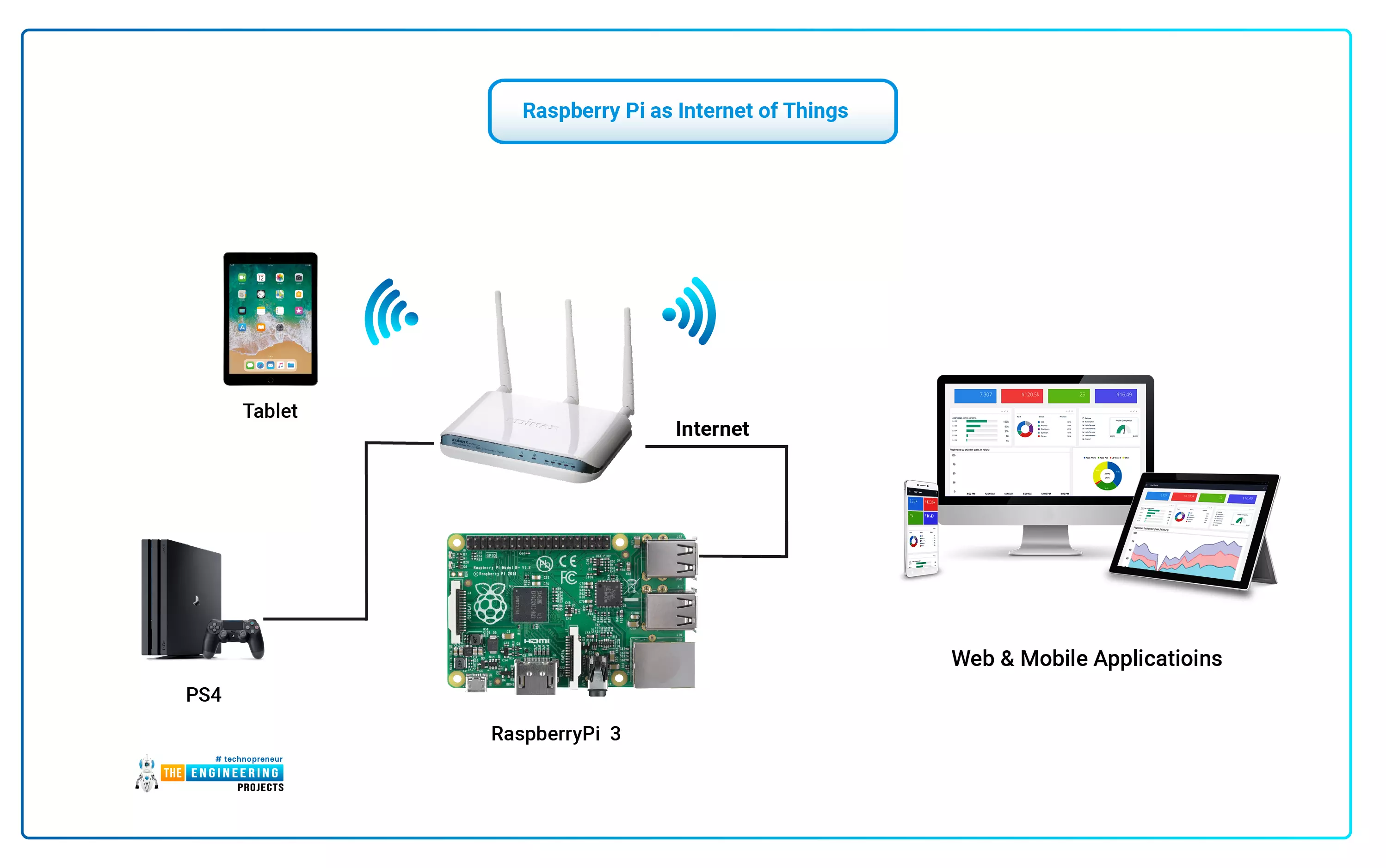
The Internet of Things (IoT) philosophy may be viewed as a highly dynamic and radically dispersed networked system comprised of a huge number of identifiable smart devices. These objects may communicate and interact with one another, as well as with end-users and other network entities. As the Internet of Things era begins, the usage of small, inexpensive, and flexible computer hardware that allows end-user programming becomes more prevalent. The Raspberry Pi, a fully configurable and programmable tiny computer board, is one of them discussed in this article. Although there are certain limitations, the Raspberry Pi remains a low-cost computer that has been used effectively in a wide range of IoT vision research applications despite its few shortcomings.

Introduction:

Introductory Notes The Internet of Things - IoT – may be viewed as a highly dynamic and widely dispersed networked system. For example, it is a network of linked smart objects that may communicate and interact with one another, as well as with end-users or other network entities, such as users or other entities in the network. Safety, security, comfort, convenience, and energy savings are maximised when smart devices can perceive physical phenomena and transform them into data streams, as well as when smart devices can trigger actions. These systems should:

  • allow new applications to be built on existing systems,
  • allow new systems to be deployed in parallel with existing systems,
  • allow an adequate level of interoperability so that innovative and competitive cross-domain systems and applications can be developed.
  • The IoT systems will be designed, managed, and used by multiple stakeholders, each with its own business model.
  • The above figure shows Raspberry Pi Model A (left) and Model B (right) board:
  • The Raspberry Pi’s core components are shown in the above figure.

While internet access can be achieved through an Ethernet/LAN cable or a USB dongle (WiFi connectivity), a USB connector is required [5, 6]. Figure 1 shows an example of a formalised formalised formalised formal Model A (left) and Model B (right) Raspberry Pi boards Figure 2: The Raspberry Pi's essential components The Raspberry Pi, like any other computer, is powered by an operating system. Raspbian is a fantastic Linux alternative for Raspberry Pi since it is free and open-source, keeping the platform's price cheap and making it more hackable. There are a few non-Linux OS alternatives available as well [5]. The Raspberry Pi offers a wide range of applications, which is one of its best features. The remainder of the article will discuss what allows it, as well as the performance and limits of the Raspberry Pi. The performance of the Raspberry Pi will be compared against the following IoT prototype platforms (Fig. 3): Arduino is an open-source physical computing platform that is built on a basic microcontroller board and includes a programming environment for creating software for the board (Fig. 3 a). It can accept information from a number of sensors and operate lights, motors, and other actuators to influence its environment. The Arduino programming language and the Arduino Integrated Development Environment may be used to programme the microcontroller on the hardware board (IDE). Arduino has two operating modes: stand-alone and linked to a computer via USB cable [3]. BeagleBone Black Is a single-board computer based on low-power Texas Instruments processors and the ARM architecture.

TABLE I

  • COMPARISON OF PLATFORMS’ SIZE, WEIGHT AND COST

B. Strength and Memory The suggested platforms' major objective is low power consumption in order to fulfil the multi-year application requirements. Only by combining low-power hardware components and low-duty-cycle operating approaches can ultra-low-power operation be accomplished.

As previously indicated, the Raspberry Pi requires up to 700mA to operate. The Raspberry Pi device may be powered by a variety of power sources (provided they can deliver adequate current 700mA), such as a computer USB port or powered USB hub (depending on power output), special wall warts with USB ports, mobile phone backup battery (depending on power output), cell phone solar charger, alkaline batteries (six rechargeable AA batteries and a voltage regulator). The Raspberry Pi's main power supply constraint is that no external device should use more than 100mA from any of its USB ports.

In terms of storage, the gadget should have enough memory to store the gathered data. In addition to storage capacity, programme memory should be sufficient to execute simple computations and send just the necessary data and routing information if the device is connected to a network. It is crucial to understand that the Raspberry Pi does not have a hard drive and that everything is saved on a Secure Digital (SD) Card. The minimum needed SD card capacity is 2 GB, however larger SD cards with capacities of 32 GB, 64 GB, or more are available but frequently prohibitively costly. This storage may be increased by employing devices that supply an extra hard drive through USB ports. These are referred to as USB Mass Storage (UMS) devices and can be traditional hard drives, solid-state drives (SSDs), or even tiny pocket-sized flash drives. Table II provides a comparative study of platform CPU, memory, and power.

TABLE II

  • COMPARISON OF PLATFORMS’ CPU, MEMORY AND POWER

C. Adaptability To be useful in a wide range of applications, the architecture must be adaptable and versatile. Furthermore, for economic considerations, it must make it simple to build precisely the correct mix of software and hardware components. As a result, these devices need an extraordinary level of hardware and software flexibility while being efficient [10]. The adaptability and universality of any gadget, on the other hand, are its strengths. One of the best things about the Raspberry Pi is its versatility; there is no one way to utilise it. It can, for example, be used for: broad purpose computing, capable of interfacing with other electronic boards and communicating with other computing devices using a range of various protocols such as Serial Peripheral Interface (SPI) and Inter-Integrated Circuit (I2C): o I2C – low-speed interface – Inter-Integrated Circuit (I2C) is a serial bus interface that can communicate with numerous devices using only two wires. It operates at relatively modest speeds. o Serial Peripheral Interface Bus (SPI) – Serial Peripheral Interaction Bus (SPI) is a synchronous full-duplex (two-way) serial connection. The Raspberry Pi Model B Rev 2 features an enhanced variety of connections in addition to the usual GPIO port [13]. P5 header has 8 pins (+3.3 V, +5 V, two ground pins, and four GPIO pins that can offer the second I2C protocol) and P6 header has two pins — their short-circuiting enables soft reset of BCM2835. Table III examines the expansion connections used by the Raspberry Pi and other platforms to connect to a broad range of external devices.

TABLE III

  • COMPARISON OF PLATFORMS’ EXPANSION CONNECTORS

The Ethernet connector on the Raspberry Pi serves as the primary interface for communicating with other devices. It is auto-sensing, so it may be linked to a router or directly to another computer (without the use of a crossover connection) [5, 6]. Model B features a conventional RJ45 Ethernet connector, but model A lacks one but may be linked to a wired network using a USB Ethernet adapter. The USB Ethernet adapter offers two speeds: 10 Mb/s and 100 Mb/s (Table IV). When you attach a cable to the Raspberry Pi, it will immediately get the information it needs to connect to the Internet when it loads its operating system through the Dynamic Host Configuration Protocol (DHCP). This gives the Raspberry Pi an Internet Protocol (IP) address and informs it which gateway to use to connect to the Internet (typically the IP address of router or modem). The Raspberry Pi's drawback is the absence of an inbuilt WiFi module, however, this functionality may be added via USB dongles. As a result, the Raspberry Pi may be used to create ad-hoc networks or to connect to a variety of wireless networks, including those that utilise the newest 802.11n high-speed standard [11]. Raspberry Pi can serve static webpages, but it can also produce dynamic content by utilising databases and web apps. It can also offer access to its GPIO ports via web technologies. In addition, Raspberry Pi may be used as a Sensor Web node by connecting it to a network and making it accessible to other computers.

Emerging user programming trends enable non-professional end-users to customise products to meet their unique demands. There are hundreds of products available now that allow end-user programming. Using affordable hardware and open-source software, it is feasible to programmatically manage numerous devices in such a manner that the own solution satisfies user demands. Furthermore, giving end-users with skills and the ability to mould goods to their requirements benefits both users and product creators. One of the prototype systems that allows end-user programming will be explored in this work. The Raspberry Pi computer board will be highlighted, including a comparison of its performance and limitations with current popular prototyping platforms [2]. The primary objective of this research is to identify and explain the benefits and drawbacks of the Raspberry Pi, as well as the capabilities of its use in the construction of the future generation of IoT. The remainder of this paper is arranged as follows. Section 2 contains an overview of the Raspberry Pi, its main components, and a detailed comparison with other existing IoT systems. The final section includes closing thoughts that summarise Raspberry Pi's merits and drawbacks as IoT hardware.

II. COMPARISON OF THE RASPBERRY PI WITH OTHER IoT

HARDWARE PLATFORMS

Smart items are key to the Internet of Things vision. These things, which are equipped with information and communication technology, can preserve their context, are networked together, can access Internet services, and communicate with one another and with humans [3]. Raspberry Pi is a tiny, powerful, inexpensive, hackable, and educational computer board that was released in 2012. (Fig. 1). It functions similarly to a normal PC, needing a keyboard for command entry, a display unit, and a power source. This credit card-sized computer with numerous capabilities and a price range of $25-35$ is an ideal platform for interacting with a variety of devices. The overwhelming bulk of the system's components, including its central and graphics processing units, audio and communications gear, and a 256 MB (Model A) – 512 MB (Model B) memory chip, are integrated into a single component. The Raspberry Pi board seen in Figures 1 and 2 comprises both necessary (CPU, the graphics chip, programme memory - RAM) and optional components (various interfaces and connectors for peripherals). The SD Flash memory acts as a hard drive for the Raspberry Pi CPU. The tiny Cortex-A8 core powers the device (Fig. 3 b). It is a tiny computer the size of a credit card that can run an operating system such as Linux/Android 4.0. The primary distinction between it and Arduino is that it can run a tiny operating system, thereby transforming it into a minicomputer capable of running applications on various operating systems. BeagleBone is intended to operate at a much higher level and has far greater computing capability than Arduino.

Phidgets are a collection of “plug and play” building pieces for bridging the physical and virtual worlds using low-cost USB sensing and control from a PC. Phidgets contain USB-based hardware boards for input (temperature, movement, light intensity, RFID tags, switches, and so on) and output actuators (servo motors, LED indicators, LCD text displays, and so on) (Fig. 3 d). Because of its design and API, programmers can discover, observe, and control all Phidgets linked to a single computer. All of the needed software components are packaged as an ActiveX COM Component. Each Phidget component necessitates the usage of a corresponding visual component, which provides a visual on-screen interface for interactive end-user control. The system includes a broad API library and may be used with a wide range of applications, including other toolkits in some situations. Using Phidgets, programmers may quickly create physical interfaces without requiring an extensive understanding of electrical design difficulties.

Udoo is a small PC with an integrated Arduino-compatible board that can run both Android and Linux. It is an extremely capable prototype board for software development and design. Udoo incorporates a microcomputer with the most popular communication interfaces (Ethernet, WiFi, USB, HDMI, SATA, digital and analogue input/output) as well as a microcontroller with a standard pinout for rapid prototyping applications. As a result, Udoo is open hardware, low-cost platform outfitted with an ARM i.MX6 Freescale CPU and an Arduino Due compatible portion based on the ATMEL SAM3X ARM processor. The creators of Udoo say that the board will have the processing power of four Raspberry Pis. Udoo's retail lineup consists of three versions, all of which share the majority of features and differ mainly in connection and the i.MX6 CPU utilised [9]: Udoo Quad, Udoo Dual, and Udoo Dual Basic.

What is Raspberry Pi 4? Pinout, Specs, Projects & Datasheet

Hi Folks! I welcome you on board. Today, I am sharing the 2nd tutorial in the Raspberry Pi 4 learning series. In this post today, we’ll cover What is Raspberry Pi 4? Raspberry Pi 4 Pinout, Specs, Projects, Datasheet etc.

Raspberry Pi 4 is a tiny dual-display single-board computer, developed by Raspberry Pi Foundation. This foundation has introduced a series of Raspberry Pi boards to teach computer basics in schools. With Raspberry Pi 4, you can control two monitors at once. Moreover, it is incorporated with a quad-core processor that is powerful and comes with more speed compared to its predecessors. I suggest you read this post till the end as I’ll cover Raspberry Pi 4 in detail. Let’s get started.

What is Raspberry Pi 4?

  • Raspberry Pi 4 is a dual-display, single-board computer (introduced on 24th June 2019) and is widely used in automation and robotics. It is highly economical and has a leg over previous modules in terms of speed and performance.
  • This module is tiny, robust, and can fit into difficult-to-reach places. It is laced with GPIO pins and can be employed for several typical computer operations i.e. surfing the web, writing programs, computing complex equations etc.
  • Raspberry Pi 4 features Gigabit Ethernet, coupled with Bluetooth(BLE) and onboard wireless networking.
  • This device comes with a powerful and efficient 1.5GHz quad-core processor which is considered the brain of this device. It features everything needed to process input/output and store information.
  • The CPU clock frequency of this machine is 1.5GHz which plays a key role in the synchronization of internal functions.
  • This module is available with variants of RAM including 1GB, 2GB, 4GB and 8GB which you can select based on your requirements. The RAM temporarily stores the information and with the removal of the power supply from the module, this memory is also wiped off, the reason it is called volatile memory.
  • Two mini HDMI ports are available on the board. These ports are employed for transmitting audio and video signal between devices.
  • This machine supports different communication protocols including I2C, SPI, and UART which are used to lay out the communication with external devices.
  • Raspberry Pi 4 comes with three USB ports out of which one is a USB-C power port used to power up the module. While others are USB 2.0 and USB 3.0 ports .
  • In these USB ports, you can connect external peripheral devices like mice, webcams, and keyboards for additional functionality.
  • Using this tiny computer you can make a range of embedded projects. Just connect this module with the computer through the USB port and start playing with it as you like better.
  • Raspberry Pi 4 is normally used in Robotics, IoT and Embedded Projects.

Raspberry Pi 4 Pinout

  • The following figure represents the Raspberry Pi 4 pinout:

Raspberry Pi 4 Pin Description

This was the little intro to the Raspberry Pi 4. In this section, we’ll cover the description of each pin incorporated into this tiny module.

Power and Ground in RPi4

This board comes with three types of power pins.
  1. 5V
  2. 3V3 (3.3V)
  3. Ground (0V)
For example, if you have PIR or humidity sensors, you can use these power pins to power up those sensors.

GPIO Pins in Raspberry Pi 4

  • GPIO pins are general-purpose input/output pins that are used for connection with external devices. These pins can be configured to either general-purpose input or general-purpose output pins or as one of up to six special settings those functions are pin-dependent.
  • External labels (from GPIO2 to GPIO27) come with the Broadcom (BCM) naming convention. This convention is useful when you are going to program with Python libraries.
  • Internal labels (from 1 to 40) project the Board naming convention. This convention is useful when BCM is not supported. It is used with some programming libraries.

SPI Pins in Raspberry Pi 4

  • This Raspberry Pi 4 module comes with SPI (serial peripheral interface) communication protocol. This is the type of communication protocol that is used for master-slave communication.
  • It is employed to layout the communication between the controller and other peripheral devices like shift registers and sensors. Two Pins are used for SPI communication… i.e. MOSI (master output slave input) and MISO (master input slave output)
  • The data synchronization is done by using a clock (SCLK at GPIO11) from the master (RPi) and the data is conveyed to the SPI component from the module using the MOSI pin. If the component needs to reply to our module, then it sends back data through the MISO pin.

I2C Pins in Raspberry Pi 4

  • This RPi4 module is incorporated with the I2C communication protocol. That comes with two pins SDL and SCL.
  • The SCL is the serial clock line that ensures the synchronization of data transfer over the I2C bus and the SDL is the serial data pin that carries the data while. This communication protocol requires master-slave roles between the devices.

UART Pins in Raspberry Pi 4

  • This board also features UART serial communication protocol. The UART serial port comes with two pins Rx and Tx.
  • The Tx is the transmission pin that is used for the transmission of serial data and Rx is the receiving pin that guarantees the receiving of serial data.

Raspberry Pi 4 Datasheet

Before incorporating this device into your project, it’s wise to scan through the Raspberry Pi 4 datasheet. The datasheet comes with the main characteristics of the device. You can download the Raspberry Pi 4 datasheet by clicking the link below.

Raspberry Pi 4 Specs

The following are the specs of Raspberry Pi 4.
  • Comes with Broadcom BCM2711, Quad-core Cortex-A72 (ARM v8) 64-bit SoC 1.5GHz processor
  • 4 GHz and 5.0 GHz IEEE 802.11ac wireless, Bluetooth 5.0, BLE
  • Carries Gigabit Ethernet to connect computers in physical space
  • RAM is available with different memories. Pick from 2GB, 4GB, or 8GB LPDDR4-3200 SDRAM (depending on model)
  • 2-lane MIPI DSI display port
  • 2-lane MIPI CSI camera port
  • One USB 3.0 port; One USB 2.0 port and One USB-C power port.
  • 2 × micro-HDMI ports that can support a 4K display
  • 4-pole stereo audio and composite video port
  • H264 (1080p60 decode, 1080p30 encode), H.265 (4kp60 decode)
  • OpenGL ES 3.0 graphics
  • Raspberry Pi standard 40-pin GPIO header (which is compatible with previous modules)
  • Contains a Micro-SD card slot for loading the operating system and data storage
  • 5V DC via GPIO header (minimum 3A*)
  • Power over Ethernet (PoE) enabled (requires separate PoE HAT)
  • Operating temperature: 0 – 50 degrees C ambient
  • 5V DC via USB-C connector (minimum 3A*)

Difference between Raspberry Pi Zero and Raspberry Pi 4

  • You’ll find a range of tiny computers in the Raspberry series. They are used to develop embedded systems and automation projects.
  • Raspberry Pi Zero is the earlier version of the Raspberry Pi series that was introduced in Nov 2015. This machine is incorporated with a single-core 1GHz processor with no Ethernet and WiFi modules on the board. Moreover, there is only one mini HDMI port available on the board. And the RAM of this module is 512MB.
  • While Raspberry Pi 4 is the advanced version of the Raspberry Pi series and was introduced in June 2019. It is better in terms of speed and performance compared to the Pi Zero module.
  • RPi4 features a quad-core dual display processor with a CPU clock speed of 1.5GHz. Plus, it also incorporates an Ethernet port which is the traditional way to connect devices in a wired local area network (LAN) or wide area network (WAN), allowing devices to communicate with each other via a protocol. An Ethernet is a physical wire on which the data is transmitted.
  • Raspberry Pi 4 comes with two HDMI ports that can support two 4K displays. Plus, the RAM of this module comes in variant i.e. pick from 1GB, 2GB, and 4GB LPDDR4.

Raspberry Pi 4 Applications

The following are the Raspberry Pi 4 Applications.
  • Used in making a portable game console
  • Employed in-network Ad-blocker
  • Used in Airplay speaker
  • Used in wearable timelapse camera
  • Incorporated in-home network music system
  • Used in embedded system IoT projects
  • Employed in making guitar pedal
  • Used in making FPV robot
  • Incorporated in WiFi security camera
That’s all for today. This was all about the Raspberry Pi 4 module. If you have any questions you can pop your comment in the section below. I’d love to help you the best way I can. Feel free to share your valuable feedback and suggestions around the content we share so we keep producing quality content tailored to your exact needs and requirements. Thank you for reading this post.

Syed Zain Nasir

I am Syed Zain Nasir, the founder of <a href=https://www.TheEngineeringProjects.com/>The Engineering Projects</a> (TEP). I am a programmer since 2009 before that I just search things, make small projects and now I am sharing my knowledge through this platform.I also work as a freelancer and did many projects related to programming and electrical circuitry. <a href=https://plus.google.com/+SyedZainNasir/>My Google Profile+</a>

Share
Published by
Syed Zain Nasir