 BETA
Wire the controllers
Connect TX, RX and direction to each transceiver. Use a receive-default pull-down.
Build a basic MAX485 circuit with labeled pins, component values and connection guidance.
Physical transceivers, cable-end terminators and one bias network.
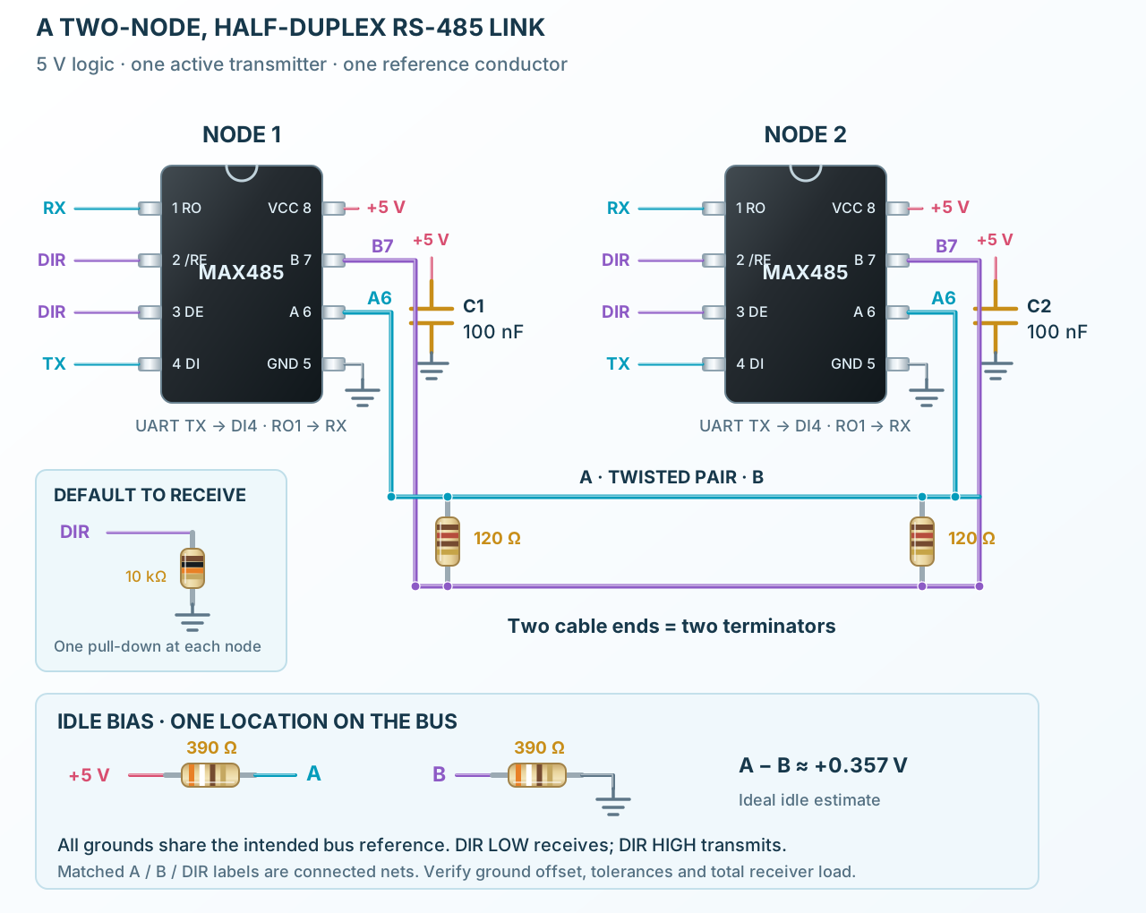
Follow the component values and pin connections
Connect TX, RX and direction to each transceiver. Use a receive-default pull-down.
Terminate only the two cable ends. The shown idle-bias pair is installed at one location.
Only one node transmits at a time. Wait for its final stop bit before releasing direction.