 BETA
Power and clock
Use compatible5 V logic, local bypassing and a valid20 MHz clock.
Build a basic MCP2515 circuit with labeled pins, component values and connection guidance.
MCP2515 plus the separate MCP2562 bus transceiver.
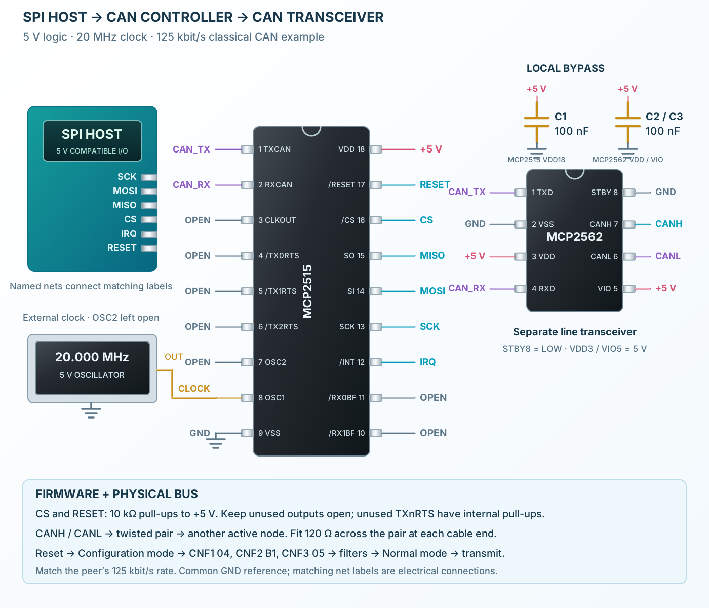
Follow the component values and pin connections
Use compatible5 V logic, local bypassing and a valid20 MHz clock.
Reset and program the125 kbit/s timing in Configuration mode before requesting Normal mode.
The external transceiver drives CANH/CANL. Terminate both cable ends and provide a matching active peer.