 BETA
NE556 Working Principle
Learn how NE556 works with an illustrated explanation and practical readings.
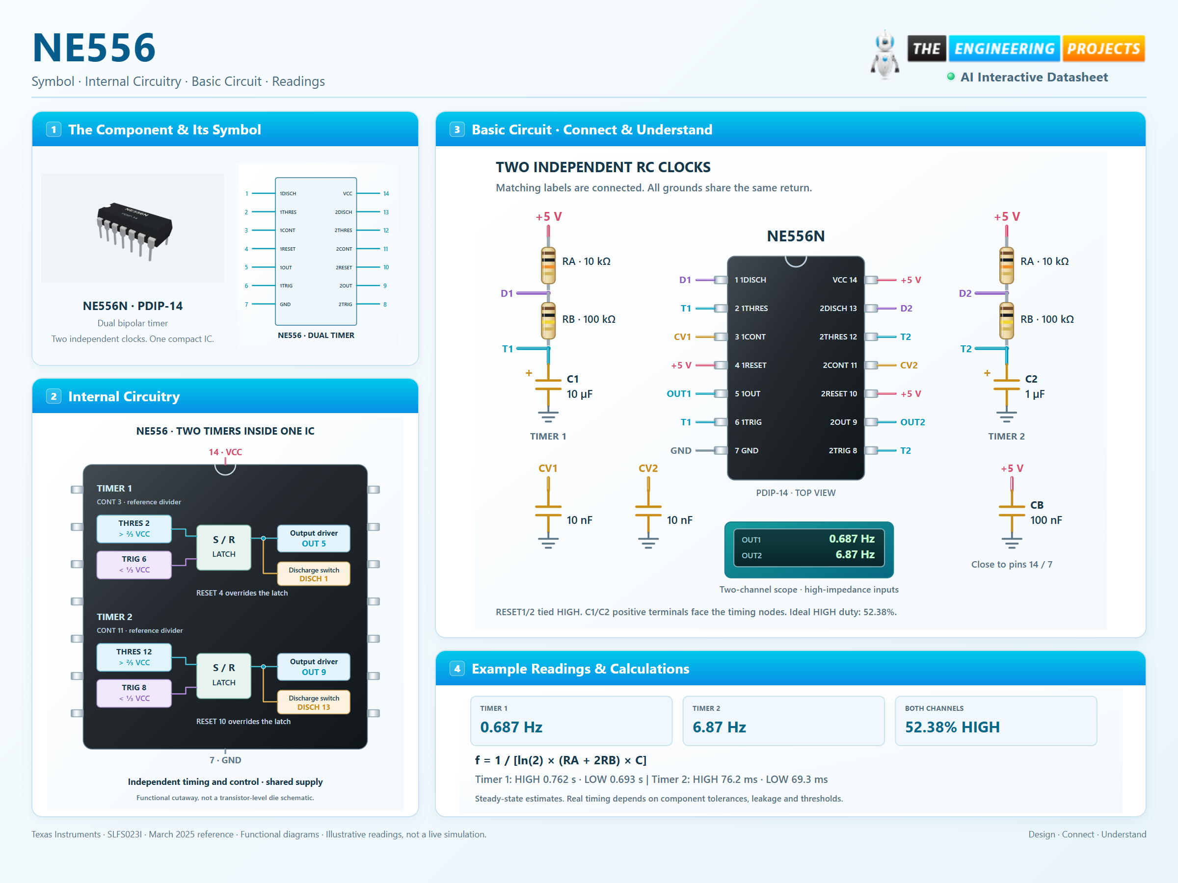
NE556 at a glance
Follow the labeled connections and functional stages
How it works
3 stages · Explore one step at a time
Charge a timing capacitor
With the discharge switch open, each capacitor charges through its RA + RB network. The output remains HIGH until the upper threshold is reached.
Discharge and repeat
The latch then drives the output LOW and connects DISCH to ground. The capacitor discharges through RB until the lower threshold starts another cycle.
Run both channels independently
The two networks share power, not a clock. Using 10 µF for channel 1 and 1 µF for channel 2 with equal resistors gives approximately a ten-to-one frequency ratio. They are not synchronized.
Two timing networks. Two waveforms.
Adjust each channel and compare its ideal steady-state timing.
Timer 1 OUT · pin 5
Timer 2 OUT · pin 9
Supply: 5 V. Each graph uses its own time scale. Nominal astable timing, not an electrical simulation. Output amplitudes, tolerances, leakage, startup and loading are not modeled. Both RESET inputs are assumed HIGH; CONT is unmodulated.