 BETA
Limit input current
Drive the anode through 750 Ω; return the cathode only to GND_A.
Build a basic PC817 circuit with labeled pins, component values and connection guidance.
Physical package, two supplies and two separate grounds.
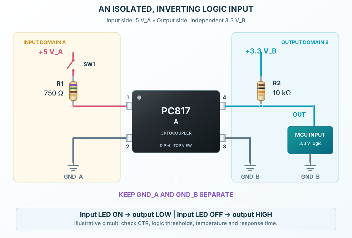
Follow the component values and pin connections
Drive the anode through 750 Ω; return the cathode only to GND_A.
Pull the collector up to the independently powered 3.3 V_B rail through 10 kΩ.
Connect the collector to the receiving logic input and the emitter to GND_B. Check the receiver’s logic thresholds.