 BETA
Store energy
Connect the 2.2 µH inductor between the source and L3.
Build a basic TPS61200 circuit with labeled pins, component values and connection guidance.
Physical contact numbering, inductor, local capacitors and feedback.
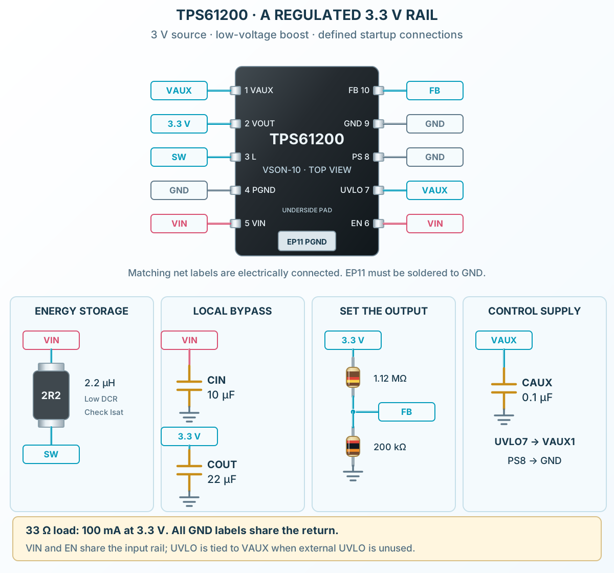
Follow the component values and pin connections
Connect the 2.2 µH inductor between the source and L3.
Fit VAUX capacitance, tie UVLO to VAUX and define EN and PS.
Fit the output capacitor and divider, then verify startup and load behavior.