 BETA
Current-mode PWM controller
UC3842A Working Principle
Learn how UC3842A works with an illustrated explanation and practical readings.
Package view
UC3842A at a glance
Follow the labeled connections and functional stages
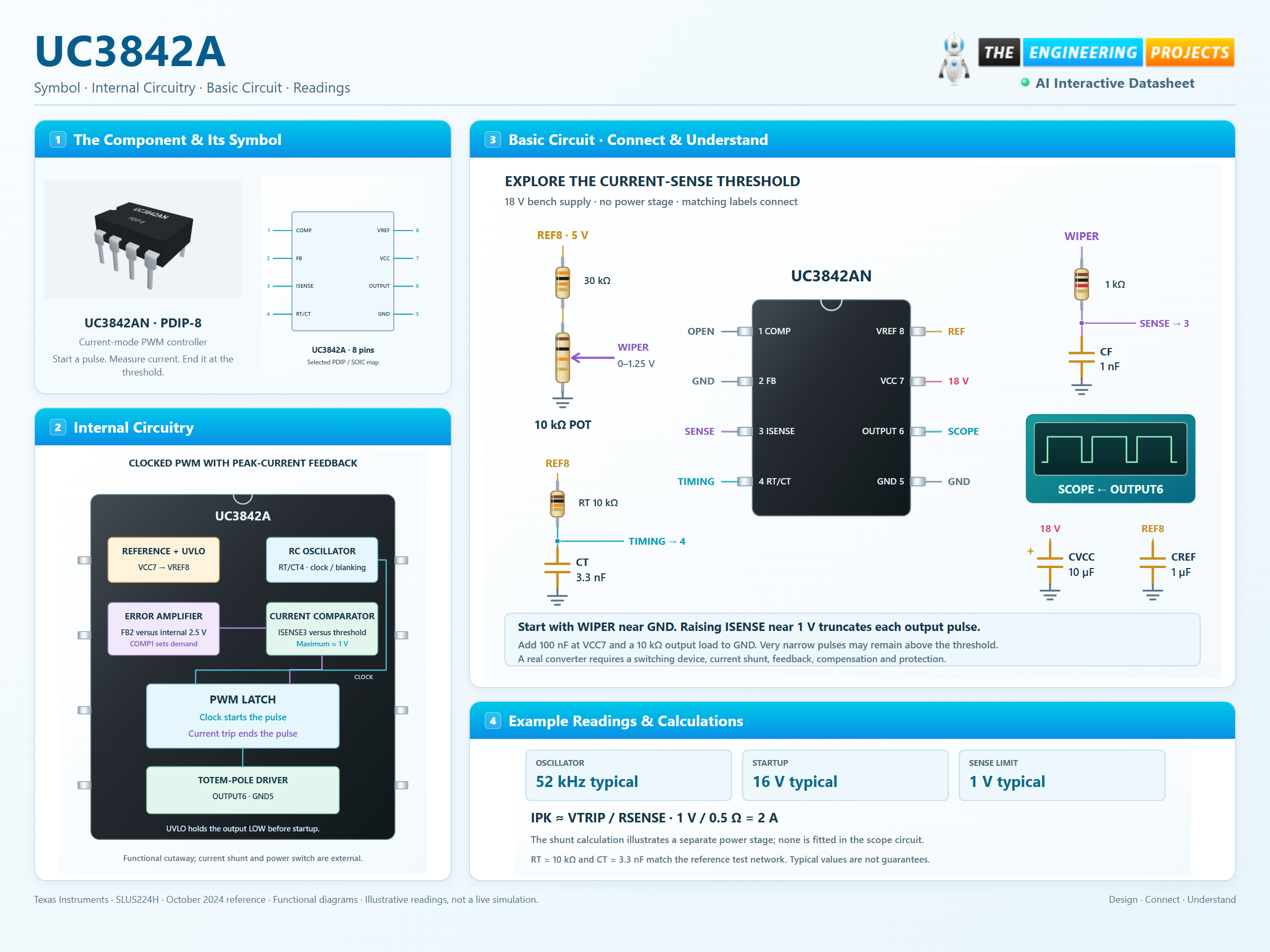
How it works
3 stages · Explore one step at a time
Cross the startup threshold
VCC must first reach the start threshold. After startup, hysteresis permits operation at a lower voltage.
Set the peak-current demand
The error amplifier compares FB with 2.5 V. COMP programs the current-comparator trip point, up to the internal limit.
Terminate the pulse
A sufficiently high ISENSE signal resets the PWM latch. Oscillator blanking also limits maximum duty.
Step 1 of 3