


First Project using STM32 in STM32CubeIDE


We will use for our examples STM32CubeIDE released by ST and completely free. STM32CubeIDE is a development tool and supports multi operative system (SO), which is part of the STM32Cube software ecosystem. STM32CubeIDE allows using a single platform to configure peripherals, to generate/compile/debug the code for STM32 microcontrollers and microprocessors. The framework used is Eclipse®/CDT, as tool-chain for the development is used GCC toolchain and GDB for the debugging.

To start the project, you must first select the MCU and then initialize and configure the peripherals the user wants to use. At this point, the initialization code is generated. At any time, the user can go back and change initializations and configurations, without affecting the user code. We will dive into these steps with a simple example in the next paragraph.
First Project in STM using STM32CubeIDE
- First of all, you have to install on your PC the STM32CubeIDE. In order to do it, you have to go on the ST site and after registered in it you can navigate to "https://www.st.com/en/development-tools/stm32cubeide.html" to download it.
- At this point, you can install it, if you'll find problems you can check the "UM2563 - STM32CubeIDE installation guide".

- STM32 Nucleo board (in our example we will use NUCLEO-L053R8, but you can use the one you prefer, as already said all Nucleo boards are pinout compatible);
- USB 2.0 Cable - A-Male to Mini-B Cord to connect PC to ST-LINK;
- Breadboard to hold and connect the simple electrical components;
- Jumper Cables Kit to connect the Nucleo board to breadboard or other components;
- Various basic electrical components such as Resistors (THT), Capacitors (THT), Buzzers, LEDs, etc.
Blinking LED using STM32 Nucleo Board
- Turning a LED on and off is a basic and classical experiment when dealing with NUCLEO for the first time.
- First, let's turn on the led, to do this we have to connect the LED to the power supply (on Nucleo we can find 3.3V and 5V).
- the power supply 5V;
- LED forward voltage of LED 7 Volt;
- LED maximum forward current 20mA;
We must connect in series to LED a resistor. What resistance value must be considered to limit the current to 20 mA (see the formula below)?
R > 5 - 1.7/0.02 , where R > 165 ?
A good value of R is 220 ?.
Now we must be able to turn off the led, to do it we need a switch to connect and disconnect the power supply as shown below.

In this case when the switch is closed the Led is ON, when the switch is open the Led is OFF. This can be easily done with a Nucleo board by configuring a GPIO (General Purpose Input Output) pin.
The steps required to configure a core board are explained below. Obviously, this is a very simple practical example, but peripherals, communication protocols and anything else can be configured in a similar way.
Steps to generate the config. files from STM32CubeMX
As already said, we will use for our examples a NUCLEO-L053R8 board. For our examples, so also a Windows PC is required. The ST-Link USB connector is used both for serial data communications, and firmware downloading and debugging on the MCU. A Type-A to mini-B USB cable must be connected between the board and the computer. The USART2 peripheral uses PA2 and PA3 pins, which are wired to the ST-Link connector. In addition, USART2 is selected to communicate with the PC via the ST-Link Virtual COM Port. A tool that emulates the serial communication terminal is necessary to view received messages and send them. You can download many open-source tools as Tera Term. In this way, you can display on PC the messages received from the board over the virtual communication Port and the other way around.
In this paragraph, we will initialize the peripherals using STM32CubeMX. The STM32CubeMX tool to create the necessary config. files to enable drivers of peripheral used (for more detail read “UM1718 - User manual STM32CubeMX for STM32 configuration and initialization C code generation.”).
Steps to Follow
- Select the NUCLEO-L053R8 board looking in a selection bar within the New Project menu.
- Select the required features (debug, GPIOs, peripherals, timer) from the Pinout view: peripheral operating modes as well as assignment of relevant signals on pins.
- Configure the MCU clock tree from the Clock Configuration view.
- Configure the peripheral parameters from the Configuration view.
- Configure the project settings in the Project Manager menu and generation of the project (initialization code only).
- Update the project with the user application code corresponding to the Led blinking example.
- Compile, and execute the project on the board.
Creating a new STM32CubeMX project
- Select File -> New project from the main menu bar to open the New Project window.
- Go to the Board selector tab and filter on STM32L0 Series.
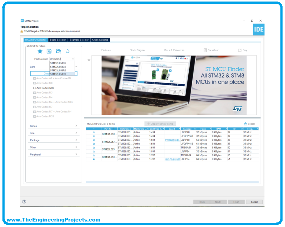
- Select NUCLEO-L053R8 board and then click on OK button to confirm. In this way the board is loaded within the STM32CubeMX user interface.

- Insert the project name, in this case, "BlinkLed" and click finish.

- Then the tool will open the pinout view.

Selecting the features from the Pinout view
- Select Debug Serial Wire under SYS, for do it click on System Core (on the topo right) and then select SYS and finally flag on “Debug Serial Wire”.

- Select Internal Clock as clock source under TIM2 peripheral. To do this click on Timers and then select TIM2. Now go to clock source and select through the drop-down menu “internal clock”.
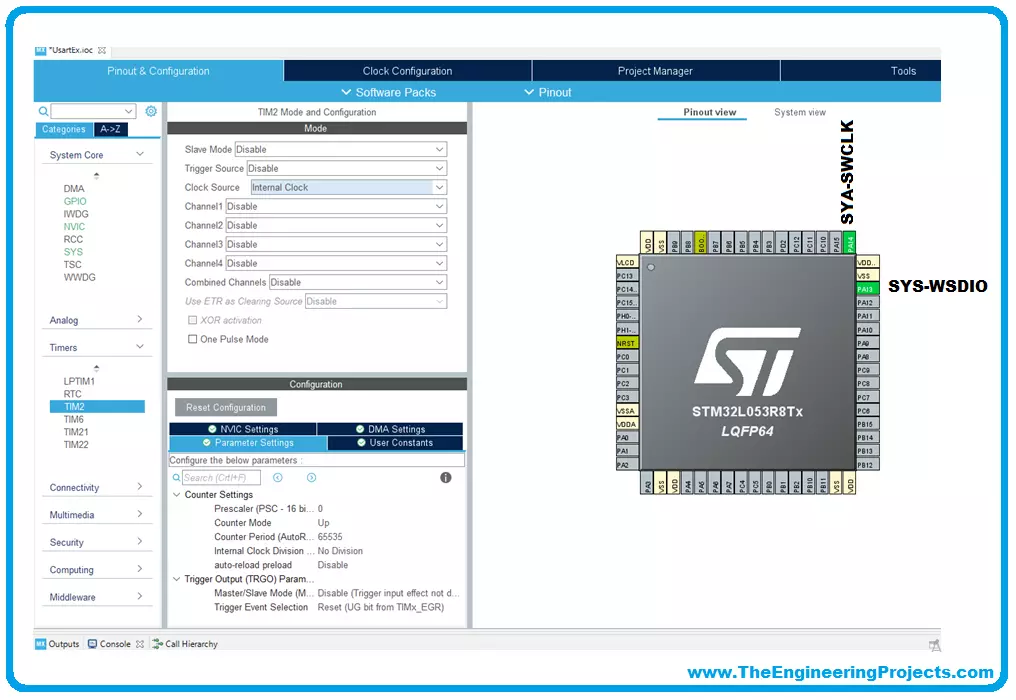
- Select one of the available pins (basically anyone!) as GPIO output, for example PA9 (the last pin of CN5)

- SYS_SWDIO on PA13
- SYS_SWCLK on PA14
- GPIO OUTPUT on PA5
Configuring the MCU clock tree
- Go to the Clock Configuration tab and in this project, there is no need to change the configuration.

Configuring the peripheral parameters
- Come back to Pinout&Configuration and select System Core -> GPIO to open the peripheral Parameter Settings window and in this case no change the configuration.

- Select Timers -> TIM2 and change the Prescaler to 16000 and the Counter Period to 1000.

- Go to the NVIC Settings tab and flag TIM2 global interrupt to enable the interrupt related to TIM2.

Configuring the project settings and generating the project
- In the Project Manager tab, configure the code to be generated and click OK to generate the code.


Updating the project with the user application code
- Our project has been initialized by STCubeMX.
- In /BlinkLed/Core/Src/main.c we will find our main where we will write the main body of our program.

STM32 Programming Code for Led Blinking
The user code must be inserted between the "USER CODE BEGIN" and "USER CODE END" so that if you go to regenerate the initializations that part of the code is not deleted or overwritten. As shown in the code below, the simplest way is to use the function:
- HAL_GPIO_TogglePin(GPIOx, GPIO_Pin) in the infinite loop ( while (1) ) with a chosen delay, for example of 1 second. To do this we use the function HAL_Delay(Delay). The declarations of these two functions with their parameters are described below
- HAL_GPIO_TogglePin(GPIOx, GPIO_Pin): Toggles the specified GPIO pins.
- GPIOx: Where x can be (A..E and H) to select the GPIO peripheral for STM32L0xx family devices. Note that GPIOE is not available on all devices. All port bits are not necessarily available on all GPIOs.
- GPIO_Pin: Specifies the pins to be toggled.
- HAL_Delay(Delay): This function provides minimum delay (in milliseconds) based on variable incremented. In the default implementation, SysTick timer is the source of time base. It is used to generate interrupts at regular time intervals where uwTick is incremented.
Note This function is declared as __weak to be overwritten in case of other implementations in a user file.
- Delay: specifies the delay time length, in milliseconds.
So, in our case GPIOx is GPIOA and the GPIO_PIN is GPIO_PIN_9 (see below).
int main(void) { /* USER CODE BEGIN 1 */ /* USER CODE END 1 */ /* MCU Configuration--------------------------------------------------------*/ /* Reset of all peripherals, Initializes the Flash interface and the Systick. */ HAL_Init(); /* USER CODE BEGIN Init */ /* USER CODE END Init */ /* Configure the system clock */ SystemClock_Config(); /* USER CODE BEGIN SysInit */ /* USER CODE END SysInit */ /* Initialize all configured peripherals */ MX_GPIO_Init(); MX_TIM2_Init(); /* USER CODE BEGIN 2 */ /* USER CODE END 2 */ /* Infinite loop */ /* USER CODE BEGIN WHILE */ while (1) { HAL_GPIO_TogglePin(GPIOA, GPIO_PIN_9); HAL_Delay(1000); /* USER CODE END WHILE */ /* USER CODE BEGIN 3 */ } /* USER CODE END 3 */ }
Now we are ready to compile and run the project:
- Compile the project within IDE.
- Download it to the board.
- Run the program.
Another simple way is to use the function
- HAL_GPIO_WritePin(GPIOx, GPIO_Pin, PinState).
- HAL_GPIO_WritePin(GPIOx, GPIO_Pin, PinState): Sets or clears the selected data port bit.
Note This function uses GPIOx_BSRR register to allow atomic read/modify accesses. In this way, there is no risk of an IRQ occurring between the read and the modified access.
- GPIOx: where x can be (A..E and H) to select the GPIO peripheral for STM32L0xx family devices.
Note that GPIOE is not available on all devices.
- GPIO_Pin: specifies the port bit to be written.
This parameter can be one of GPIO_PIN_x where x can be (0..15).
All port bits are not necessarily available on all GPIOs.
- PinState: specifies the value to be written to the selected bit.
This parameter can be one of the GPIO_PinState enum values:
- GPIO_PIN_RESET: to clear the port pin
- GPIO_PIN_SET: to set the port pin
So, in our case GPIOx is GPIOA and the GPIO_PIN is GPIO_PIN_9 and the pin state changes between 0 (LOW or CLEAR) and 1 (HIGH or SET).
In this case, the code is the following:
while (1) { HAL_GPIO_WritePin(GPIOA, GPIO_PIN_9,0); HAL_Delay(1000); HAL_GPIO_WritePin(GPIOA, GPIO_PIN_9,1); /* USER CODE END WHILE */ /* USER CODE BEGIN 3 */ } /* USER CODE END 3 */ }
There are many other ways to blink an Led such as PWM, Interrupts etc. and will discuss it in the upcoming lectures. Thanks for reading.


