Solar Panel Library for Proteus V2.0

Hello friends, I hope you all are well. Today, we are going to share the second version of the Solar Panel Library for Proteus. You should also have a look at the first version of the Solar Panel Library, which we have posted around 2 years back and we were receiving suggestions to reduce its size as there's less space left for other components. That's why we have designed this new Solar Panel Library and have reduced the size of the solar panel. We have also added a new black solar panel component to it. So, this library contains 2 solar Panel modules in it. First, let's have a look at a brief introduction to Solar Panel and then will download the Proteus Library zip file.

What is Solar Panel?

  • Solar Panels are designed using solar cells composed of semiconductor materials(i.e. silicon, phosphorous etc.) and convert solar energy into electrical energy.
  • Solar Panels are used to generate renewable energy and are considered as one of the major sources.
  • Real Solar Panel modules are shown in the below figure:

Solar Panel Library for Proteus V2.0

  • First, we need to download the zip file of Proteus Library by clicking the below button:
Download Proteus Library zip file
  • In this zip file, you need to open the folder named Proteus Library Files.
  • In this folder, you will find 2 Proteus Library files named:
    • SolarPanel2TEP.IDX
    • SolarPanel2TEP.LIB
  • Copy-paste these files in the Library folder of Proteus software.
Note:
  • After adding the files in Proteus software, open it and if you are already working on it, then you need to restart it.
  • In the components section, make a search for solar panel and you will get results as shown in the below figure:
  • In the above figure, the first result is from version 1.0, and the remaining two are added by this new solar library.
  • Let's place these sensors in the Proteus workspace, as shown in the below figure:
  • This Solar Library has thee two solar panels in it, one is blue and the second one is black.
  • Both are of 12V but their voltage level can be changed from the Properties panel.
  • In order to open the Properties panel, double click on the solar panel and you can change the value of Voltage here, as shown in the below figure:
  • Click Ok to close the properties panel.
Now let's design a simple Proteus simulation of Solar Panel in Proteus:

Proteus Simulation of Solar Panel

  • I have changed the voltage level of black solar from the properties panel & simply placed a voltmeter in front of these solar panels, as shown in the below figure:
  • Now let's run the Proteus simulation of solar panel:
  • As you can see in the above figure, the output of black solar is around 16V, while blue solar is giving 12V.
  • That's how you can test it for variable voltage i.e. day time, night time etc.
So, that was all for today. I hope this library will help you guys in your engineering projects. If you have any issues/queries, use the below comment form. Thanks for reading. Have a good day. :)

Vibration Sensor Library for Proteus V2.0

Hello friends, I hope you all are doing great. In today's tutorial, I am going to share a new Vibration Sensor Library for Proteus V2.0. It's the second version of the Vibration Sensor Library for Proteus. In this library, we have four vibration sensors. These vibrations sensors have both digital and analog output pins and can easily be connected with microcontrollers i.e. Arduino, PIC, Atmel etc. Before downloading the Proteus Library zip file, let's first have a look at the brief overview of Vibration Sensor:
Where To Buy?
No.ComponentsDistributorLink To Buy
1Arduino UnoAmazonBuy Now

What is Vibration Sensor?

  • A vibration sensor is a small embedded sensor, which is used to detect vibrations on any surface.
  • These vibration sensors are used for various purposes i.e. fault detection on heavy machinery, placed on doors & windows for security etc.
  • Real vibration sensors are shown in the below figure:

Vibration Sensor Library for Proteus V2.0

  • First of all, download the zip file of Proteus Library for Vibration Sensor, by clicking the below button:
Download Proteus Library Files
  • After downloading the zip file, extract its files and open the folder named "Proteus Library Files".
  • In this folder, you will find 3 Proteus Library Files named:
    • VibrationSensor2TEP.IDX
    • VibrationSensor2TEP.LIB
    • VibrationSensor2TEP.HEX
  • We need to place these files in the Library folder of Proteus software.
Note:
  • After adding these library files, open your Proteus software or restart it, if it's already running.
  • In the components section, make a search for Vibration, and you will get results, as shown in the below figure:
  • In the above search result, the first four modules are from V2.0, while the fifth one is of the first version.
  • Let's place these first four modules in the Proteus workspace, as shown in the below figure:

Adding Hex File to the Sensor

  • Next, we need to add the hex file of the sensor, so double click on the sensor to open its Properties Panel.
  • In the Program File section, browse to the hex file, which we have downloaded above and placed it in the Library folder of Proteus software:
  • After adding the hex file, click the Ok button to close the properties panel.
The vibration sensor is now ready to simulate in Proteus, so let's design a simple circuit to understand its working:

Vibration Sensor Proteus Simulation

  • I have simulated two of these vibration sensors, as shown in the below figure:
  • As you can see, I have placed an LC filter on the analog output of the vibration sensor, its because proteus gives us a peak to peak voltage value and we need t convert it to Vrms.
  • This LC filter is not required in real hardware.
  • Now, let's run the Proteus simulation and if everything's fine, you will get results as shown in the below figure:
  • As the potentiometer value is different on both sensors, that's why we are getting different outputs.
So, that was all for today. I hope this sensor will help engineering students in their projects' simulations. Thanks for reading. Have a good day. Bye !!! :)

CR2032 Lithium Coin Library for Proteus

Hello friends, I hope you all are well. In today's tutorial, I am going to share a new CR2032 Lithium Coin Library for Proteus. This small cell is extensively used in electronics whereabouts because of its small size. CR2032 is not present in the Proteus components' database and we are quite pleased that we are sharing it for the first time. This library contains 3 types of these small cells, one is the cell itself, while the other two models are cells with leads. Before downloading the Proteus Library zip file, let's first have a brief overview of CR2032:

What is CR2032???

  • CR2032(also called Lithium Coin) is a small round Lithium Manganese Dioxide battery, normally provides 3V.
  • As CR2032 is very small in size, thus used in small electronics devices & whereabouts i.e. watches, bracelets, calculators, hand-held video games etc.
  • CR2032 is a small cell, so a black or yellow casing is used to operate it.
  • Here are few images of real CR2032 with casing:

CR2032 Library for Proteus

  • First of all, download the zip file of Proteus library for CR2032, by clicking the below button:
Download Proteus Library Files
  • Open the zip file of Proteus Library and extract the files.
  • Open the folder named Proteus Library Files and you will find 2 files in it, named:
    • CR2032LibraryTEP.IDX
    • CR2032LibraryTEP.LIB
  • Copy these files and paste them into the Library folder of Proteus software.
Note:
  • Now, open Proteus ISIS and in the components section, search for CR2032 and you will get results, as shown in the below figure:
  • Let's place these three components in the Proteus workspace, as shown in the below figure:
  • As you can see in the above figure, the first one is the cell CR2032 itself, and in the second and third, we have tried to create a Cell with leads & casing.
Now, let's simulate them in proteus to have a look at their output:

CR2032 Proteus Simulation

  • Here's the Proteus simulation of CR2032, where I have simply placed a voltmeter in front of these coins, as shown in the below figure:
  • Now simply run the Proteus simulation, and you will get results as shown below:
  • They all are providing 3V as shown on the voltmeters but you can change the voltage level from their properties panel.
So, that was all for today. I hope this Lithium coin will help you in your proteus simulations. Thanks for reading. Take care. Bye !!!

Proteus Library of Single Cell Battery

Hello friends, I hope you all are doing well. In today's tutorial, I am going to share a new Proteus Library of Single Cell Battery. These single-cell batteries are not present in Proteus, so we have designed them, I hope you guys will find them helpful. This Proteus library has 5 Single Cell Batteries in it, we have designed the most common ones. Four of these batteries provide 3.7V, while one provides 12V. First, let's have a look at

What is a Single Cell Battery???

  • Single Cell Batteries are available in different voltage ranges and normally provide 3.7 volts.
  • Single Cell Battery is used in small electronic projects i.e. toys, clocks, alarms, calculators etc.
  • Few Single Cell Batteries are shown in the below figure, which we have simulated in Proteus:

Proteus Library of Single Cell Battery

  • First of all, click on the below button to download the Proteus Library zip file of Single Cell Battery:
Download Proteus Library Files
  • Extract the files of this zip file and open the folder named Proteus Library Files.
  • In this folder, you will find three library files, named:
    • SingleCellBatteryTEP.IDX
    • SingleCellBatteryTEP.LIB
    • SingleCellBatteryTEP.HEX
  • We need to place these files in the Library folder of our Proteus software.
Note:
  • After adding the Library files, restart your Proteus ISIS software.
  • In the components section, make a search for "Single Cell" and you will find these results:
  • Let's place these Single Cells in our Proteus workspace, and they will look something like this:
  • These Single Cells will provide 3.7V, but you can change the voltage level from its Properties panel.
  • So, double click on any of these batteries & the properties panel will open up, as shown in the below figure:

Single Cell Battery Proteus Simulation

  • Now, let's design a simple Proteus simulation.
  • I have just placed a voltmeter in front of three of these sensors, as shown in the below figure:
  • Now, run the simulation and you will get results as shown in the below figure:
  • The center one is of 12V, while all others are of 3.7V.
  • You can use these batteries to power up your electronic circuits.
So, that was all for today. If you have any questions/suggestions, please use the below comment form. Thanks for reading. Have a good day. Bye !!! :)

Sound Detector Library for Proteus V2.0

Hello friends, I hope you all are doing great. In today's tutorial, we are going to share a new Sound Detector Library for Proteus. It's actually the second version of our previous library Sound Sensor Library for Proteus. We have changed the name as "Sound Detector" is written on these sensors. Moreover, this new sensor is quite small-sized, compact and also has an analog output pin. We were receiving many complaints about the large size of the previous sound sensor, as it occupies more space and there's less space left for other components. So, this new one is quite small-sized and I am hopeful students will find it helpful. So, let's first have a look at What is Sound Detector Sensor and why is it used?
Where To Buy?
No.ComponentsDistributorLink To Buy
1Arduino UnoAmazonBuy Now

What is Sound Detector Sensor???

  • Sound Detector sensor is an Embedded sensor, used for the detection of sound in the surroundings.
  • It has both analog & digital outputs and thus gives us information about the intensity of sound as well i.e. how low or high the sound is?
  • So these sensors are used for sound detection but they are not used for sound recognition.
Now let's download the Proteus Library of Sound Detector Sensor and simulate it:

Sound Detector Library for Proteus V2.0

  • First of all, download the proteus library of Sound Detector Sensor by clicking the below button:
Download Proteus Library Files
  • You will get a zip file of Proteus Library, extract these files and open the folder named "Proteus Library Files".
  • In this folder, you will find three files, titled:
    • SoundDetector2TEP.IDX
    • SoundDetector2TEP.LIB
    • SoundDetector2TEP.HEX
  • We need to place these three library files in the Proteus Library folder.
Note:
  • Once added the Library files, now open your Proteus software or restart it. (In order to index the library components, proteus has to restart)
  • In the components section, make a search for sound detector and you will get 4 results, shown in the below figure:
  • Now, let's place all these sensors in the Proteus workspace:

Adding Hex File to the Sensor

  • In order to simulate this sensor in Proteus, we need to add a hex file to the sensor.
  • So, double click on the sensor or right-click on it and then click on Edit Properties and it will open up the Properties Panel.
  • In the Properties panel, we have a textbox titled Upload Hex File and here we need to add the hex file, which we have placed in the library folder of Proteus, as shown in the below figure:
Now our sensor is ready to simulate, so let's design a simple circuit to understand its working:

Sound Detector Simulation in Proteus

  • As we have seen this sensor consists of 5 pins in total, which are:
    • V: Vcc (Power).
    • G: Ground.
    • D0: Digital Output.
    • A0: Analog Output.
    • Test: For Testing Purposes. (It's not present in real sensor)

Why Test Pin is used?

  • As we can't add a real mic in Proteus simulation, so in order to simulate this sensor, we have placed this Test Pin.
  • So, when the voltage at Test Pin will increase, the sensor will consider it as sound intensity is increasing.
  • We need to connect a potentiometer with this Test Pin.

Sound Detector Circuit Diagram

  • Now, we need to design a simple circuit in Proteus, as shown in the below figure:
  • As you can see in the above figure, I have placed an LC filter on the analog output, because we are getting peak to peak voltage and we need to convert it to Vrms.
  • We don't need to place this LC filter with the real sensor.
  • Now, let's run this simulation and if everything's good, you will get results as shown in the below figure:
  • I have simulated two of these sound detector sensors and you can see they have different outputs because they have different voltage at their Test Pins.
So, that was all for today. If you have any problem in simulating the sound detector, ask in the below comments. We will soon share its simulation with Microcontrollers. Thanks for reading. Take care !!! :)

Infrared Tracker Sensor Library for Proteus

Hello friends, I hope you all are doing great. Today, I am going to share a new Infrared Tracker Sensor Library for Proteus. By using this library, you will be able to simulate IR based tracker sensor. This library contains 4 tracker sensors in it. This Infrared Tracker Sensor is not present in Proteus software and we are sharing it for the first time. We have already shared 2 Proteus Libraries of Infrared sensors, you should check them as well. Note: First, let's have a look at what is tracker sensor and why is it used?
Where To Buy?
No.ComponentsDistributorLink To Buy
1IR Tracker SensorAmazonBuy Now
2Arduino UnoAmazonBuy Now

What is IR Tracker Sensor???

  • IR Tracker Sensor uses Infrared technology and contains two IR LEDs on it.
  • A signal is transmitted from one LED, which is reflected back after hitting some target and is received by the second LED.
  • This sensor is normally used in Line Tracking Robotic Projects, where the black line is sensed by this IR Tracker sensor.

Infrared Tracker Sensor Library for Proteus

  • First of all, download the zip file of Proteus Library by clicking the below button:
Download Proteus Library Files
  • Once you downloaded the zip file, extract it and open the folder named "Proteus Library Files".
  • You will find three files in it, named:
    • InfraredTrackerSensorTEP.IDX
    • InfraredTrackerSensorTEP.LIB
    • InfraredTrackerSensorTEP.HEX
  • Place these three files in the Library folder of your Proteus software.
Note:
  • Now open your Proteus software or restart it, if it's already running.
  • In the components section, we need to make a search for Infrared Tracker Sensor, and you will get results as shown in the below figure:
  • As you can see in the above figure, now we have 4 infrared tracker sensors in our Proteus database.
  • Let's place these sensors in the Proteus workspace, that's how they will look like:

Adding Hex File to the sensor

  • Now we need to add the hex file to the sensor, so double click on the sensor to open its Properties Panel.
  • In the properties panel, we have a textbox named "Program File".
  • In this textbox, browse to the hex file of the sensor, which we have placed in the Library folder of Proteus software, as shown in the below figure:
  • After adding the hex file, click the OK button to close the properties panel.
Our sensor is now ready to operate.

Infrared Tracker Sensor Pinout

  • As you can see these sensors have five pins in total, which are:
    1. V: Power.
    2. G: Ground.
    3. D0: Digital Output.
    4. A0: Analog Output.
    5. Test: For Testing Purposes.

Why Test Pin is used?

  • As it's a simulation, so we can't actually generate IR pulses, that's why I have placed this Test Pin.
  • As the voltage at Test Pin will increase, the sensor will consider it as the obstacle is coming close.
  • We will place a potentiometer at this Test Pin.
  • This Test Pin is not present in a real IR Tracker sensor.
So, let's design a simple simulation of this Infrared Tracker sensor to have a look at its working:

Infrared Tracker Sensor Proteus Simulation

  • Design a simulation in Proteus, as shown in the below figure:
  • I have placed an LC circuit in front of the analog output because we have to convert the peak to peak voltage to Vrms.
  • This LC filter is also not required in real hardware, but in simulation, we need to place it to get an analog value.
  • Now, let's run our Proteus simulation of the IR sensor and if everything goes fine, you will get results as shown in the below figure:
  • I have simulated two of these sensors, the rest will work the same and as you can see depending on the potentiometer, we got different values at the output.
So, that was all for today. I hope this library will help you guys in your engineering projects. If you have any questions/suggestions, please use the below comment form. Thanks for reading. Take care !!! :)

Magnetic Hall Effect Sensor(KY-024) Library for Proteus

Hello friends, I hope you all are doing fine. Today, I am going to share a new Magnetic Hall Effect Sensor Library for Proteus. We are sharing this library for the first time and we hope it will help students in their final year & semester projects. In this library, you will find 4 models of the KY-024 Magnetic Hall Effect Sensor. First, we will have a look at the brief overview of Magnetic Hall Effect Sensor, then will add its Library in proteus and will simulate it. So, let's get started:
Where To Buy?
No.ComponentsDistributorLink To Buy
1Arduino UnoAmazonBuy Now

What is Magnetic Hall Effect Sensor?

  • Magnetic Hall Effect Sensor is used to measure the density of magnetic field in the surroundings using Hall Effect Principle.
  • KY-024 is the sensor's model used for measuring magnetic density.
  • There are many different breakout boards available but they all are using the same sensor i.e. KY-024.
So, let's install its Proteus Library and simulate it:

Magnetic Hall Effect Sensor Library(Ky-024) for Proteus

  • First of all, download the Proteus Library zip file for Magnetic Hall Effect Sensor, by clicking the below button:
Proteus Library Files
  • In this zip file, we need to open the folder titled Proteus Library Files.
  • In this folder, you will find three Proteus Library files, named:
    • MagneticHallEffectSensorTEP.IDX
    • MagneticHallEffectSensorTEP.LIB
    • MagneticHallEffectSensorTEP.HEX
  • We need to place these files in the Library folder of our Proteus software.
Note:
  • Now, open Proteus ISIS and if you are already working on it, restart it.
  • In the components search box, make a search for "Magnetic Hall" and you will get four results, as shown in the below figure:
  • Let's place these four Hall Effect sensors' models in our Proteus workspace.
So, we have successfully added these sensors to our Proteus software. Let's design a simple simulation to have a look at its working:

KY-024 Proteus Simulation

  • As we have seen this simulated model of KY-024 has five pins in total:
    1. A0: Analog output.
    2. G: Ground.
    3. V: Vcc (Power).
    4. D0: Digital output.
    5. Test: For testing purposes.

Why Test Pin is used?

  • As it's stimulation, so we can't actually create a magnetic field around the sensor, that's why we have placed this Test Pin.
  • As the voltage at Test Pin will increase, the sensor will consider it as magnetic density is increasing around.
    • If Test Pin is at 0V, the sensor will feel no magnetic field.
    • If Test Pin is 5V, the sensor will feel a maximum magnetic field.
  • We will attach a potentiometer to the Test Pin, for variable voltage levels.

Adding Hex File to the sensor

  • In order to operate the magnetic Hall Effect sensor, we need to add a hex file in its properties panel.(We have placed the hex file in the Library folder)
  • So, double click on your sensor to open its properties panel.
  • In the Upload Hex File section, browse to your sensor's hex file, as shown in below figure:
  • After adding the hex file to the sensor, click on the Ok button to close the properties panel.
Now our sensor is fully operational, so let's design its simulation:

Proteus Simulation of Magnetic Hall Effect Sensor

  • Now, let's design a simulation in Proteus software, as shown in the below figure:
  • I have attached an LED with the digital output of the sensor and a voltmeter with analog output.
  • I have also placed a simple LC filter at the analog output. This filter is not required in real hardware implementation.
  • We are using it in Proteus simulation, as Proteus gives the peak to peak value and we have to convert that PP value into Vrms.
  • If you are working on a real sensor then you don’t need to add this LC circuit.
  • Now, let's run our simulation and if everything's configured correctly, you will get results as shown in the below figure:
  • As you can see in the above figure, our sensors are working perfectly, now if you change the value of the potentiometer, their output will change accordingly.
So, that was all for today. I hope this sensor will help you guys in your final year and semester projects. If you have any questions, please ask in the comments. Thanks for reading. Take care !!! :)

Lipo Battery Library for Proteus

Hello everyone, I hope you all are fine. In today's tutorial, we are going to share a new Lipo Battery Library for Proteus. Proteus has a 12V battery module in it but they are quite simple in looks, so we have simply designed a stylish looking lipo battery, I hope you will find it useful for a better project presentation. This Proteus Library has two Lipo Batteries in it, one is of 3.7V and the second one is of 11.1V, these are normally available Lipo models in the market. Although, you can change the voltage level of these batteries from their properties panel. Let's first have a look at the brief introduction of Lipo Baterry:

What is Lipo Battery???

  • Lipo is an abbreviation of lithium polymer battery, designed using lithium-ion technology and uses polymer electrodes.
  • Lipo Battery provides high power in a small package and thus used in autonomous project i.e. quadcopter, robotic vehicles etc.

Lipo Battery Library for Proteus

  • First of all, we need to download the Proteus Library zip file of the Lipo battery, by clicking the below button:
Lipo Battery Library for Proteus
  • In this zip file, you will find a folder named Proteus Library Files.
  • In this folder, we have two files:
    • LipoBatteryTEP.LIB
    • LipoBatteryTEP.IDX
  • Place these two files in the library folder of your Proteus software
Note:
  • After adding these Library files, open your Proteus software or restart it, if it's already open.
  • In the components section, make a search for Lipo Battery and you will get results, as shown in the below figure:
  • As you can see, now we have two Lipo batteries in the components database, so let's place them in the Proteus workspace.
  • If everything's fine, then you will get results as shown in the below figure:
  • As you can see in the above figure, we have two Lipo Batteries:
    • One is operating at 11.1V.
    • Second one is operating at 3.7V
  • We can change the voltage level from the properties panel, so double click on the Lipo battery to open its properties, as shown in the below figure:
  • As you can see in the above figure, we have 11.1V written in the Voltage text box, so here you can change the voltage level of these batteries.
  • Now, let's design a simple simulation to understand how it works:
  • So, I have simply attached a voltmeter with both of these lipo batteries, as shown in the above figure.
  • Now, let's run our simulation and if everything's fine, you will get results as shown in the below figure:
  • If you are working on a 12V project, then simply change the voltage level from the properties panel and use it in your project.
So, that was all for today. I hope you have enjoyed today's tutorial. If you have any questions, please ask in comments and we will help you out. Thanks for reading.. Take care. Bye !!! :)

Soil Moisture Sensor Library for Proteus V2.0

Hello friends, I hope you all are doing fine. In today's tutorial, I am going to share a new Soil Moisture Sensor Library for Proteus V2.0. You should also have a look at its previous version i.e. Soil Moisture Sensor Library for Proteus V1.0. If you have worked on the previous version, it has only one soil moisture sensor in it, while in this library, we have added three soil moisture sensors.

First, we will have a brief introduction of the Soil Moisture sensor, then we will download the zip file containing Proteus Library files of Soil Moisture Sensor and finally, we will design a small simulation using these new sensors. So, let's get started:

Where To Buy?
No.ComponentsDistributorLink To Buy
1Arduino UnoAmazonBuy Now

What is Soil Moisture Sensor?

  • Soil Moisture sensor is an embedded sensor, used to measure the moisture level of the soil.
  • It is normally used in agricultural automation projects, i.e. controlling the water flow based on the moisture level of the soil.
  • Soil Moisture sensors are available with both analog and digital outputs.
  • They normally have a potentiometer embedded in them, for controlling the sensitivity of the sensor.

Before downloading the sensor's library file, let's first have a look at what's new in version 2.

Difference b/w V1.0 & V2.0

  • We received many complaints about the big size of the Soil Moisture sensor(V1.0), so we have reduced their sizes in this new library(V2.0).
  • The first version contains only 1 soil moisture sensor, while in V2.0 we have added three soil moisture sensors.
  • The output of V1.0 was quite smooth, while in V2.0 we have made the output a bit fluctuating to make it more realistic.

Now, let's download the Proteus Library zip file for this sensor and simulate it in Proteus:

Soil Moisture Sensor Library for Proteus V2.0

  • First, we need to download the Proteus Library zip file, by clicking the below button:
Soil Moisture Sensor Library for Proteus V2.0
  • After downloading the zip file, extract it and open the folder named Proteus Library Files.
  • You will find three files in this folder, named as:
    • SoilMoistureSensor2TEP.IDX
    • SoilMoistureSensor2TEP.LIB
    • SoilMoistureSensor2TEP.HEX
  • Place these files in the library folder of your Proteus software.
Note:
  • Now, open Proteus ISIS, and if you are already working on it, then restart it.
  • In the components library, make a search for Soil Moisture Sensor, and you will get results as shown in the below figure:
  • Let's place these three soil moisture sensors in the Proteus workspace:
  • Quite pretty, aren't they? :)

Now let's design a small simulation, to have a look at its working:

Proteus Simulation of Soil Moisture Sensor

  • As you can see in the above figure, each of these sensors has 4 pins in total, which are:
    1. Vcc: We need to provide +5V here.
    2. GND: We need to connect it to Ground.
    3. A0: It's the analog output pin, its value will increase as the moisture level of the soil will increase.
    4. TestPin: The voltage level of TestPin will decide the moisture level of the soil.

Why Test Pin is used?

  • As it's a simulation, so we can't actually probe the sensor in real soil, so we are using this TestPin for testing purposes.
  • The value of Test Pin can vary from 0 to 5V, so as the value of this Test Pin will increase, the sensor will consider the moisture level of the soil in increasing and thus its output will also increase. In simple words:
    • If TestPin is HIGH: Soil has maximum moisture level.
    • If TestPin is LOW: Soil is completely dry.
  • We will place a potentiometer at TestPin to provide variable voltage for testing.

Adding Hex File to the sensor

  • We have placed three library files of soil moisture sensor in the Library folder of Proteus, and if you have noticed, one of them is the .hex file.
  • In order to operate this sensor, we need to add that hex file to our sensor.
  • So, double click on the Soil Moisture sensor to open its Properties Panel.
  • In the properties panel, we have a section named "Program File", here upload the hex file which we have downloaded, as shown in the below figure:
  • After adding the hex file, click Ok to close the properties panel.
  • Now, design a small simulation, as shown in the below figure:(I have added this simulation in the Proteus Library zip file)
  • I have added the hex file in both of these soil moisture sensors.
  • Now, let's run the Proteus Simulation and have a look at the output:
  • As we change the value of the potentiometer(attached to Test Pin), the output of the sensor will change accordingly.

So, that was all for today. I hope this library will help embedded students in their engineering projects. If you have any suggestions/comments, please use the below comment form. Thanks for reading. Take care. Bye !!! :)

Traffic Light Simulation with D Flip Flop in Proteus

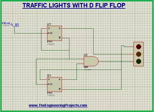
Hi Mentees! we hope you are doing great. Welcome to a super easy yet useful project based upon the simulation in Proteus. We are working on the Traffic Lights project that will work with the help of D Flip Flop. In this simple tutorial, you will be aware of the following concepts:
  1. What are the Traffic Lights using D Flip Flop?
  2. What is the role of D Flip Flop?
  3. How does the circuit of D Flip Flop work in the Traffic Lights?
  4. How can you simulate the circuit of Traffic Lights with D Flip Flop in Proteus?
In addition, you will find some important information about the Traffic Lights circuit in the DID YOU KNOW Sections. Let's start learning.

Traffic Lights with D Flip Flop

Who is not aware of the traffic lights? we all observe and use the Traffic lights on the road every day. But for the sake of the concepts, let's see the traffic lights technically.
"The Traffic Lights are the signaling devices that has an electronic circuit designed to control the flow of traffic at the roads by a specialized pattern of lights."
These traffic lights are positioned at road intersections ad pedestrian crossing and other positions where the traffic flow has to maintain. The Traffic Lights depends on an array of three lights with different colors that are connected electrically The whole system is packed into a metallic structure. The LEDs turn on and off with a special pattern that depends upon the circuit. Before moving forward, refresh the concepts of Traffic Light with the logical point of view. There are three lights in the Traffic Light Signals. These are:
  1. Red
  2. Amber
  3. Green
The red light stays last for some moments. The circuit is designed so, we get the output from the Amber color light that coordinates with the red and green light and lasts for some time. In the end, we get only Green light. All these lights are formed as a result of the sequential logic of D Flip Flop and at the end, the output of two D Flip Flops are inserted into AND Gate. The output of the Green light depends upon the AND Gate and we found the light of green LED only when the output of both the D Flip Flops are HIGH.

Role of D Flip Flop in Traffic Lights

Have you ever thought about how does the traffic light blink at a specific time? We all follow the Traffic lights but today we'll learn that what does traffic light follows. The D Flip Flops are the logical circuits and we define the D Flip Flop as:
"The D Flip Flops a dual input is Flip Flop circuit that is designed to have the input at its D Terminal, regulates the signal with the clock edge pulses and shows the output at its two output terminals."
In the Traffic Lights, we use two D Flip Flops that are responsible for the switching of the lights in on or off conditions. The D Flip Flop is the combination of the S and R Flip Flops with an inverter with one terminal. but for  simplicity, we'll use the Integrated Circuit of D Flip Flop. Hence our circuit has only four components and we get a clean, easy and useful circuit that works automatically. The input Terminals are called CLK and D terminals whereas output terminals are denoted by Q and Q'.  The Truth Table for the D Flip Flop is given next:
Inputs Output
CLK D Q Q’
0 X No Change
1 0 0 1
1 1 1 0
The X is called the don't care condition which means in this situation, the value of D does not matters. You can learn more about D Flip Flop in https://www.theengineeringprojects.com/2021/01/d-type-flip-flop-circuit-diagrams-in-proteus.html section. The output of the D Flip Flop is connected with each LED in the Traffic lights and hence we observe the on/off situations of Traffic Lights.

Working of Traffic Lights circuit with D Flip Flop

The working of the Traffic Light starts with the change in the pulse of the clock.
  1. The Q' output of the D Flip Flop 2 gives the power to the Red Light of the Traffic Light.
  2. When the clock is low, there is no change in the Q' terminal of the 1st Flip Flop then the Amber light is off.
  3. With the clock pulses, the Amber light of the Traffic Light turns on.
  4. When the clock is high, we get the output inverse of the D Flip Flop.
  5. The output Q of the D Flip Flop1 and the Q' of the D Flip Flop 2 is fed into AND Gate.
  6. We know the AND Gate is HIGH only when both of its terminals are HIGH.
  7.  This output of the AND Gate is connected with the Green Light of the Traffic Light.

Circuit Simulation of Traffic Lights in Proteus ISIS

For the simulation of Traffic Light in Proteus, simply follow the easy steps coming next.

Devices required for the Traffic Lights

  1. D Flip Flop - DTFF
  2. Traffic Lights
  3. AND Gate
  4. Clock pulses - DClock
  5. Connecting wires
  • Power up your Proteus software.
  • Click the "P" button.
  • Write the names of 1st three devices given above one by one and choose them.
  • Get D Flip Flop twice, And Gate and Traffic Lights from the pick library and arrange them on the working area.
  • Go to Generation mode(from the sidebar) >DClock and set it just on left side of the 1st D Flip Flop.
  • Connect all the components with the help of connecting wires.
  • Connect the Traffic Light's red light with the output of 1st D Flip Flop, the amber light with the D Flip Flop 2 and the green light with the output of AND Gate.
  • Pop the play button.
Does your Traffic Lights are working well? great! if not, then check the connection again. if you face any problem then share with us. Consequently, today we learned about the logic behind the Traffic Lights. We learned that with the help of D Flip Flop, one can easily design a circuit just using four simple devices. We saw the working of the sequential on/off condition of the Traffic Lights. Stay with us for more interesting circuits.
Syed Zain Nasir

I am Syed Zain Nasir, the founder of <a href=https://www.TheEngineeringProjects.com/>The Engineering Projects</a> (TEP). I am a programmer since 2009 before that I just search things, make small projects and now I am sharing my knowledge through this platform.I also work as a freelancer and did many projects related to programming and electrical circuitry. <a href=https://plus.google.com/+SyedZainNasir/>My Google Profile+</a>

Share
Published by
Syed Zain Nasir