Hello friends, i hope you all are fine enjoying. Today i am going to share a new project tutorial which is Getting Started with Arduino Programming. In the previous tutorial, which was titled as Getting started with Arduino Software, I have explained in detail the basics of Arduino software. How this software is installed and run.
Today's post is also related to arduino software but, the difference is that, in previous post we learn How to use the arduino software, What are the function keys of this software and Where to write the code(sketch) and after writing the sketch, how it is debugged. Now in today's post which is ' Getting started with Arduino Programming', we will see How a Code is written in Arduino software? What are the built-in functi ...
Hello friends, i hope you all are fine and enjoying. Today i am going to share a new project tutorial which is What is serial port? We can also judge from its name that this pin that this may be the pin used for data communication. So we can say that Serial port is such a device which is used for communication of data in a serial manner. and an important thing to remember here is that this port can communicate only one bit at a time.
Serial port is now used in almost all type of computers and it is used to connect some some devices like modems, monitors, LCDs and some models of printers to the mother board of computer. If we talk broadly then some devices connected to the computer like Ethernet, USB etc also requires serial data stream for commun ...
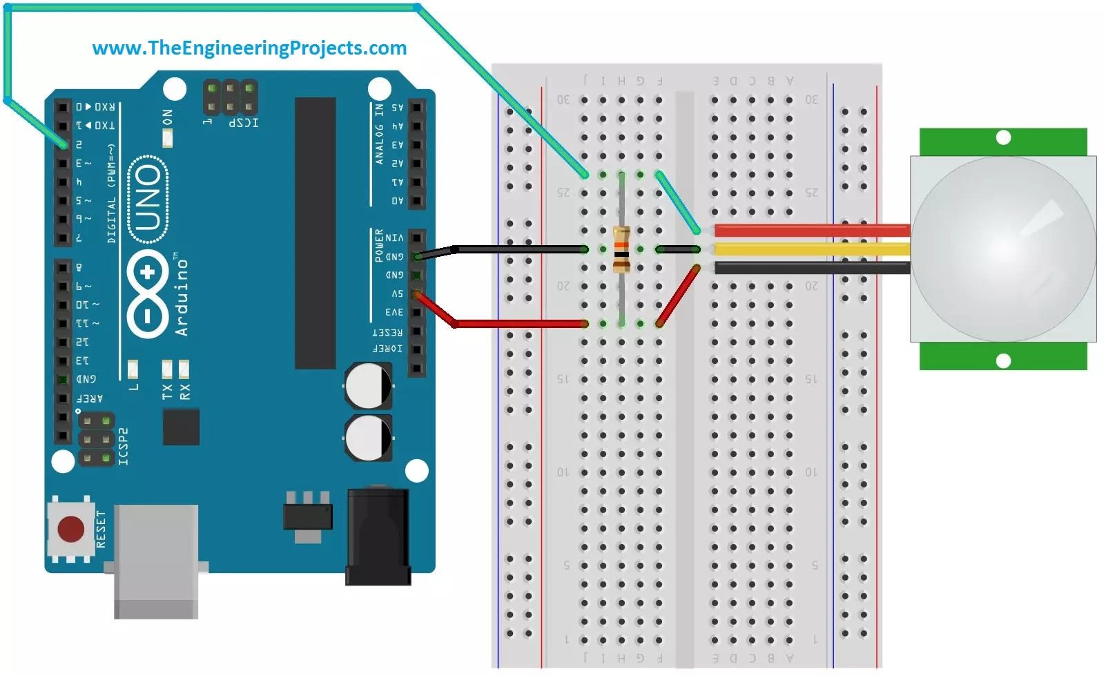
Hello friends, i hope you all are fine and enjoying. Today i am going to share a new project tutorial which is Interfacing PIR sensor with Arduino. First of all lets, have a little introduction about the basics and working of the PIR sensor. PIR sensors are in fact a Passive Infrared Sensor. PIR sensors are actually electronic sensors and they are used for motion detection. They are also used to detect the Infrared waves emitting from a particular object. You should also have a look at PIR Sensor Library for Proteus, using this library now you can easily simulate your PIR Sensor in Proteus software.
PIR sensors are widely used in motion detection projects now a days. Since my today's tutorial is about interfacing of PIR sensor with Arduino micro c ...