ESP32 Capacitive Touch Sensor in Arduino IDE

Hello readers, I hope you are all doing great. Welcome to the 2nd lecture of Section 5(ESP32 Sensors) in the ESP32 Programming Series. In the previous tutorial, we discussed the built-in ESP32 Hall Effect Sensor. In this tutorial, we will discuss another inbuilt sensor of the ESP32 i.e. Capacitive Touch Sensor.

ESP32 Board has 10 built-in capacitive touch pins, which generate an electrical signal when someone touches these pins. These ESP32 touch pins are normally used to wake up the board from deep sleep mode. These touch pins are also used to replace the normal mechanical buttons with touch pads, improving the presentation of the IoT projects.

Here's the video demonstration of the ESP32 Capacitive Touch Sensor:

Before going forward, let's first understand how this touch sensor works:

Where To Buy?
No.ComponentsDistributorLink To Buy
1ESP32AmazonBuy Now

What is a Capacitive Touch Sensor?

Capacitance is determined by the geometry of the conductors and the dielectric materials used. Changing any of these factors will result in changing the capacitance.

C = Ad

As we know, the human body also carries a small electric charge. So, when a body approaches the metallic plates(of a capacitor), the mutual capacitance between the two metal plates decreases. This change in capacitance is used to detect the touch in these capacitive sensors.

Capacitive touch sensor in ESP32

  • ESP32 offers 10 Capacitive-sensitive GPIO pins, operating at a normally HIGH state.
  • So, at open state, these pins provide +5V at the output but when someone touches any of these pins, the respective pin voltage drops to 0.
  • These ESP32 Capacitive Touch Sensor Pins are labeled in the below figure:(for detailed pinout, please read ESP32 Pinout)

So, if someone touches any of these pins, ESP32 can easily detect it. The pin mapping of touch-sensitive pins in DOIT ESP32 DevKit V1 with GPIO pins is shown below:

ESP32 Capacitive Touch Pins
No. Parameter Name Parameter Value
1
Touch0 GPIO4
2
Touch1 GPIO0(not available in DOIT ESP32 Dev-kit V1 30-pin module but available in the 36-pin module)
3
Touch2 GPIO2
4
Touch3 GPIO15
5
Touch4 GPIO13
6
Touch5 GPIO12
7
Touch6 GPIO14
8
Touch7 GPIO27
9
Touch8 GPIO33
10
Touch9 GPIO32

Programming ESP32 Capacitive Sensor

We are using the Arduino IDE development environment for programming ESP32. If you are new to Arduino IDE, read out How to Install ESP32 in Arduino IDE. Let's use the builtin Touch Sensor example in Arduino IDE:

  • Open the Arduino IDE, go to File > Examples > ESP32 > Touch. An image from Arduino IDE is attached below for your reference:

In Arduino IDE there are two example codes available for the ESP32 touch sensor. We will discuss and implement both example codes in this tutorial. So, let's first open the TouchRead Code:

ESP32 TouchRead Example

Here's the code for the TouchRead Example:

// ESP32 Touch Test
void setup()
{
    Serial.begin(115200);
    delay(1000); // give me time to bring up serial monitor
    Serial.println("ESP32 Touch Test");
}

void loop()
{
    Serial.println(touchRead(T0)); // get value using T0
    delay(1000);
}

Code Description

  • This is a basic code to test/understand the touch sensor feature of ESP32.
  • In this code, we are using a touch-sensitive pin to read the variation in capacitance and print the respective readings on the serial monitor.

Setup() Function

Inside the setup() function, the serial monitor is initialized at a baud rate of 115200 to display the sensor readings. Finally, we printed the message(ESP32 Touch Test) on the Serial Monitor:

void setup()
{
    Serial.begin(115200);
    delay(1000); // give me time to bring up serial monitor
    Serial.println("ESP32 Touch Test");
}

Loop() Function

  • Inside the loop function, the touchRead(T0) function takes the T0 capacitive sensor pin as an argument and reads the output of T0(GPIO Pin4).
  • The observed output is continuously printed on the serial monitor with a delay of 1 sec.
void loop()
{
    Serial.println(touchRead(T0)); // get value using T0
    delay(1000);
}

Testing/Result

  • Upload the above code into the ESP32 development board and connect a jumper wire to the T0 capacitive sensor pin(GPIO4).
  • To open the serial monitor in Arduino IDE, go to Tools > Serial monitor or use the Ctrl+Shift+M shortcut key.
  • Select the 115200 baud rate on the serial monitor.
  • Now hold the metal end of the jumper wire connected to the GPIO4.
  • To check the results, open the serial plotter, go to Toole > Serial Plotter or use Ctrl+Shift+L shortcut keys.
  • As you can see in the above figure, the sensor's value drops to 0 when we touch the metallic part of the capacitive sensor pin.
  • When we are not touching the sensor pin, the normal sensor output is around 107.
  • Here's the Serial Monitor showing the touch results:

ESP32 Touch Interrupt Example

These capacitive touch sensor pins are mainly used to generate an external interrupt for waking up ESP32 from low power modes(deep sleep mode). Moreover, can also be used to control external peripherals like LED blinking or tuning on a DC motor, when a capacitive touch-interrupt is observed. So, let's have a look at How to Generate external interrupt by touching the ESP32 capacitive touch pins:

ESP32 Touch Interrupt Code

Here's the ESP32 Touch Interrupt Code:

const int CAPACITIVE_TOUCH_INPUT_PIN = T0; // GPIO pin 4
const int LED_OUTPUT_PIN = LED_BUILTIN;
const int TOUCH_THRESHOLD = 40; // turn on light if touchRead value < this threshold
volatile boolean _touchDetected = false;

void setup()
{
    Serial.begin(115200);
    pinMode(LED_OUTPUT_PIN, OUTPUT);
    pinMode(LED_OUTPUT_PIN, LOW);
    touchAttachInterrupt(CAPACITIVE_TOUCH_INPUT_PIN, touchDetected, TOUCH_THRESHOLD);
}

void touchDetected()
{
    _touchDetected = true;
}

void loop()
{
    if(_touchDetected)
    {
        Serial.println("Touch detected.");
        _touchDetected = false;

        Serial.println("blink the LED");
        digitalWrite(LED_OUTPUT_PIN, HIGH);
        delay(1000);
        digitalWrite(LED_OUTPUT_PIN, LOW);
        delay(1000);
    }
}

Let's understand the code by parts:

Variables Initialization

  • The first step is to select the GPIO or touch sensor input pin to trigger an interrupt. We are using T0 or GPIO4 as an interrupt pin.
  • Select the LED output pin which will react or blink on the occurrence of an interrupt.
  • In the code, we are using the threshold value of 40. When a body, containing an electric charge touches a touch-sensitive pin, the threshold value decreases below 40.
  • The default state of the touchDetect variable is set to false.
const int CAPACITIVE_TOUCH_INPUT_PIN = T0; // GPIO pin 4
const int LED_OUTPUT_PIN = LED_BUILTIN;
const int TOUCH_THRESHOLD = 40; // turn on light if touchRead value < this threshold
volatile boolean _touchDetected = false;

Setup() Function

  • In the Setup Function, we initialized the serial monitor with a baud rate of 115200 so that you can display the results on the serial monitor for debugging purposes.
  • Set the LED pin as output and set the default state to LOW.
  • Attach the interrupt with the capacitive touch pin T0 using touchAttachInterrupt(), it takes the T0 pin, touchDetected and threshold value as arguments.
void setup()
{
    Serial.begin(115200);
    pinMode(LED_OUTPUT_PIN, OUTPUT);
    pinMode(LED_OUTPUT_PIN, LOW);
    touchAttachInterrupt(CAPACITIVE_TOUCH_INPUT_PIN, touchDetected, TOUCH_THRESHOLD);
}
  • touchDetected() function will be called when an interrupt is triggered i.e. someone touches the T0 Pin.
  • This Function will change the state of the "_touchDetected" variable to true.
void touchDetected()
{
    _touchDetected = true;
}

Loop() Function

  • Inside the loop() function, we are using the ‘if’ statement which is continuously checking the state of variable "_touchDetected".
  • Once the variable state is changed to true, an interrupt is triggered and the output LED (inbuilt LED) will start blinking with a delay of 1 second.
  • The result will be printed on the serial monitor.
void loop()
{
    if(_touchDetected)
    {
        Serial.println("Touch detected.");
        _touchDetected = false;

        Serial.println("blink the LED");
        digitalWrite(LED_OUTPUT_PIN, HIGH);
        delay(1000);
        digitalWrite(LED_OUTPUT_PIN, LOW);
        delay(1000);
    }
}

Testing of ESP32 Touch Sensitive Pin

  • Open the serial monitor with a 115200 baud rate.
  • Connect a male-to-female jumper wire with T0 or GPIO 4 of ESP32.
  • Hold the metallic end of the jumper wire.
  • LED will blink with a delay of 1 sec.
  • See the results displayed on the serial monitor.

This concludes the tutorial; I hope you found this helpful and also hope to see you again with a new tutorial on ESP32.

ESP32 Hall Effect Sensor in Arduino IDE

Hello readers, I hope you all are doing great. Welcome to Section 5 of the ESP32 Programming Series. In this section, we are going to interface different Embedded Sensors with the ESP32 Microcontroller Board. ESP32 development board is featured with some inbuilt sensors(i.e. hall effect sensor, capacitive touch sensor) so, in the initial tutorials of this section, we will explore these built-in ESP32 sensors and in the later lectures, we will interface third-party sensors with the ESP32.

In today's lecture, we will discuss the working/operation of the ESP32 built-in Hall Effect Sensor. Hall Effect sensor is used to detect the variation in the magnetic field of its surroundings. So, let's first understand What's Hall Effect:

Where To Buy?
No.ComponentsDistributorLink To Buy
1ESP32AmazonBuy Now

What is the Hall Effect?

The Hall Effect phenomenon was first discovered by Edwin Hall in 1879. When current passes through a conductor, the electrons move in a straight line and thus the voltage difference across the conductor's surface remains zero, as shown in the below figure:

However, when a magnet is placed near the current-carrying conductor in a way that the direction of the magnetic field is perpendicular to the flow of current, the electrons get diverted and don't follow a straight line, which results in generating a small potential difference across the conductor's surface, as shown in the below figure:

This small potential difference generated because of magnetic field presence is called Hall Voltage. This magnetic field influence over the current-carrying conductor is termed the Hall Effect.

Hall Effect Sensor

A Hall Effect Sensor is a non-contact type embedded sensor, used to detect the presence & intensity of a magnetic field in its surroundings. Different third-party Hall Effect Sensors available in the market are shown in the below figure:

  • A normal Hall Effect Sensor Pinout consists of 3 Pins i.e.
  1. Vcc: Normally +5V, few +3.3V are also available.
  2. GND: We need to provide Ground here.
  3. OUT: The Output Pin to give the sensor's response.
  • When a perpendicular magnetic field is placed near a Hall-effect sensor, it changes the status of its Output Pin.
  • The analog Hall Effect Sensors can also detect the strength of the magnetic field i.e. greater the magnetic field greater will be the sensor's output or voltage deviation.

Applications of Hall Effect sensor

  • In an Automotive system, Hall Sensors are used to detect speed, distance, position etc.
  • Used in Proximity sensing.
  • Used in Current sensing.
  • Used in Anti-lock braking system.
  • Used in Internal combustion engines to assist with ignition timing.
  • To switch an electric circuit ON and OFF.

Hall Effect Sensor in ESP32

In ESP32, the Hall effect sensor is located inside the ESP-WROOM-32 metallic cover. As the Hall Effect sensor is a non-contact type, it doesn't have to be in contact with the magnet. We just need to place the magnet above this metallic sheet and the ESP32 Hall Effect sensor will detect it.

Programming ESP32 Hall Effect Sensor using Arduino IDE

To understand the working of the Hall sensor with ESP32, let's test the builtin ESP32 example:

  • You can find the code through File> Examples> ESP32 > Hall Sensor, as shown in the below figure:

Arduino IDE code

Here's the code for this ESP32 Hall Sensor example:

int val = 0;

void setup()
{
   Serial.begin (9600);
}

void loop() 
{
   val = hallRead();
   Serial.print ("sensor value = ");
   Serial.println (val);//to graph

   delay(100);
}

Code Description

The code is quite simple, where the hallRead() function is called to read the hall sensor value, store it into a variable and then print it on the Serial monitor. Finally added a small delay to get the next value. Let me explain the code line by line for the beginners:

Variables Declaration

  • The first step will be the declaration of an integer-type variable to store the hall sensor value. The initial value assigned to the variable is zero.
int val = 0;

Setup() Function

  • Inside the setup function, the only task is to initialize the serial port at a 9600 baud rate for serial communication.
void setup()
{
   Serial.begin (9600);
}

Loop() Function

  • Inside the loop function, we called a function ‘hallRead()’ to read the sensor value and store those readings into the variable ‘val’.
  • Printed the sensor readings on the serial monitor or serial plotter using serial.println() function.
  • A delay of 0.3 sec is added at the end.
void loop() 
{
   val = hallRead();
   Serial.print ("sensor value = ");
   Serial.println (val);//to graph

   delay(100);
}

ESP32 Hall Effect Sensor - Testing

  • After successfully uploading the code into ESP32, open the serial plotter or serial monitor to monitor the results.
  • Place a magnet near the ESP32 board.
  • The sensor reading will increase/decrease depending on the magnet pole(i.e. North or South Pole) facing the Hall sensor.
  • Now click on Tools > Serial Plotter to visually analyze the sensor's output.
  • The Serial Plotter of our project is shown in the below figure:
  • As you can see in the above figure, the sensor is giving negative output when facing the North Pole of the magnet.
  • In the case of a South Pole, the sensor's output is positive.
  • In the absence of a magnetic field, the sensor's output is almost 0.
  • The distance between the magnet and the Hall sensor decides the amount of potential difference generated.
  • The greater the distance between the two, the smaller the hall voltage or potential difference will be.
  • We have attached an image from the Arduino IDE serial monitor for your reference.

This concludes the tutorial. I hope you found this helpful, test it out and if feel any difficulty, let me know in the comments. In the next tutorial, we will have a look at another built-in sensor of ESP32 i.e. Capacitive Touch Sensor. Thanks for reading.

ESP32 Over The Air (OTA) Web Updater

Hello readers, I hope you are all doing great. In this tutorial, we are going to discuss the OTA web updater on the ESP32.

We already covered the fundamentals of OTA programming in ESP32, in our previous tutorial where we used the Arduino IDE to upload OTA code into the ESP32 module using the network port.

In the OTA web updater, you need to create a web server page for OTA programming.

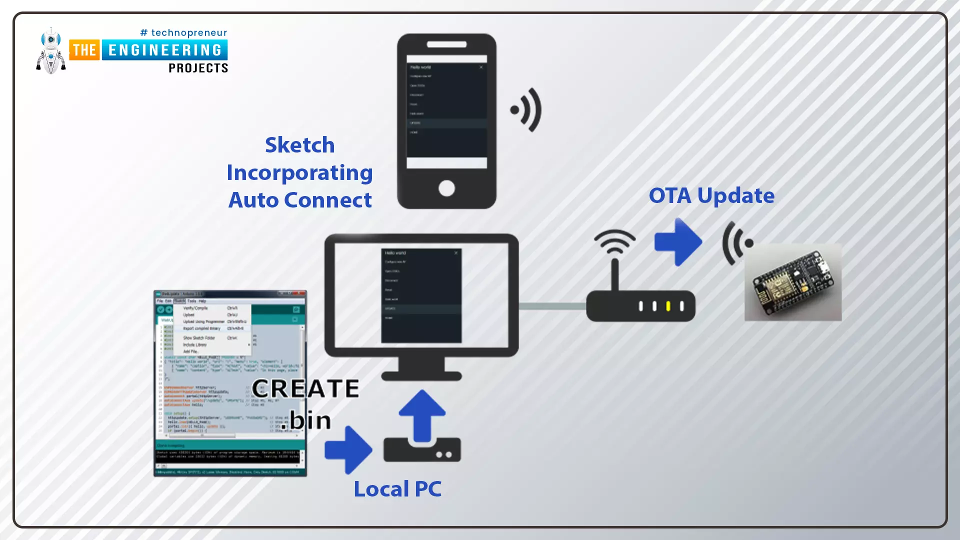
[caption id="attachment_166886" align="aligncenter" width="1920"] ESP32 OTA web updater[/caption]

Fig.1 ESP32 OTA web updater

Where To Buy?
No.ComponentsDistributorLink To Buy
1ESP32AmazonBuy Now

Over the Air Web Updater

  • "Over-the-air" refers to the ability to wirelessly download an application, configuration, or firmware to internet-enabled devices, also known as IoT. (OTA). It functions similarly to our computers, laptops, tablets, and phones.
  • Instead of using a serial port and a wired medium to upload a code, the OTA web updater allows the user to update the code or firmware wirelessly via a web server.
  • When sensor nodes are frequently placed in remote or difficult-to-reach locations, OTA programming can be used.

Steps to implement an OTA web updater using ESP32

  • Using the serial communication port, upload the code containing the instructions to enable the OTA web updater (so that in the future you can update the code using a browser instead of a wired medium).
  • The code uploaded via the serial port will launch a web server, allowing you to upload new code over the air.
  • The new code, which has been uploaded using a web server, should contain instructions to keep the OTA web updater enabled on the ESP32 board so that you can use the OTA programming feature in future applications as well.
  • Create a .bin using Arduino IDE compiler and upload the file on the server.

Fig. 2

Code for OTA web updater implementation in ESP32

In this tutorial, we will discuss only the OTA web updater method using Arduino IDE and ESP32 dev-Kit V1 module.

If you want to know more about the basics of ESP32 and how to get started with Arduino IDE, then read Introduction to ESP32 Programming Series.

  • You can find the code through File> Examples> ArduinoOTA> BasicOTA.
  • An image has been attached below for reference:

Fig. 3

  • This code should be uploaded serially through a serial communication port only then you can access the OTA web updater feature.

Code

#include <WiFi.h> #include <WiFiClient.h> #include <WebServer.h> #include <ESPmDNS.h> #include <Update.h>   const char* host = "esp32"; const char* ssid = "SSID"; const char* password = "password";   WebServer server(80);   /* * Login page */   const char* loginIndex = "<form name='loginForm'>" "<table width='20%' bgcolor='A09F9F' align='center'>" "<tr>" "<td colspan=2>" "<center><font size=4><b>ESP32 Login Page</b></font></center>" "<br>" "</td>" "<br>" "<br>" "</tr>" "<td>Username:</td>" "<td><input type='text' size=25 name='userid'><br></td>" "</tr>" "<br>" "<br>" "<tr>" "<td>Password:</td>" "<td><input type='Password' size=25 name='pwd'><br></td>" "<br>" "<br>" "</tr>" "<tr>" "<td><input type='submit' onclick='check(this.form)' value='Login'></td>" "</tr>" "</table>" "</form>" "<script>" "function check(form)" "{" "if(form.userid.value=='admin' && form.pwd.value=='admin')" "{" "window.open('/serverIndex')" "}" "else" "{" " alert('Error Password or Username')/*displays error message*/" "}" "}" "</script>";   /* * Server Index Page */   const char* serverIndex = "<script src='https://ajax.googleapis.com/ajax/libs/jquery/3.2.1/jquery.min.js'></script>" "<form method='POST' action='#' enctype='multipart/form-data' id='upload_form'>" "<input type='file' name='update'>" "<input type='submit' value='Update'>" "</form>" "<div id='prg'>progress: 0%</div>" "<script>" "$('form').submit(function(e){" "e.preventDefault();" "var form = $('#upload_form')[0];" "var data = new FormData(form);" " $.ajax({" "url: '/update'," "type: 'POST'," "data: data," "contentType: false," "processData:false," "xhr: function() {" "var xhr = new window.XMLHttpRequest();" "xhr.upload.addEventListener('progress', function(evt) {" "if (evt.lengthComputable) {" "var per = evt.loaded / evt.total;" "$('#prg').html('progress: ' + Math.round(per*100) + '%');" "}" "}, false);" "return xhr;" "}," "success:function(d, s) {" "console.log('success!')" "}," "error: function (a, b, c) {" "}" "});" "});" "</script>";   /* * setup function */ void setup(void) { Serial.begin(115200);   // Connect to WiFi network WiFi.begin(ssid, password); Serial.println("");   // Wait for connection while (WiFi.status() != WL_CONNECTED) { delay(500); Serial.print("."); } Serial.println(""); Serial.print("Connected to "); Serial.println(ssid); Serial.print("IP address: "); Serial.println(WiFi.localIP());   /*use mdns for host name resolution*/ if (!MDNS.begin(host)) { //http://esp32.local Serial.println("Error setting up MDNS responder!"); while (1) { delay(1000); } } Serial.println("mDNS responder started"); server.on("/", HTTP_GET, []() { server.sendHeader("Connection", "close"); server.send(200, "text/html", loginIndex); }); server.on("/serverIndex", HTTP_GET, []() { server.sendHeader("Connection", "close"); server.send(200, "text/html", serverIndex); });   /*handling uploading firmware file */ server.on("/update", HTTP_POST, []() { server.sendHeader("Connection", "close"); server.send(200, "text/plain", (Update.hasError()) ? "FAIL" : "OK"); ESP.restart(); }, []() { HTTPUpload& upload = server.upload(); if (upload.status == UPLOAD_FILE_START) { Serial.printf("Update: %s\n", upload.filename.c_str()); if (!Update.begin(UPDATE_SIZE_UNKNOWN)) { //start with max available size Update.printError(Serial); } } else if (upload.status == UPLOAD_FILE_WRITE) { /* flashing firmware to ESP*/ if (Update.write(upload.buf, upload.currentSize) != upload.currentSize) { Update.printError(Serial); } } else if (upload.status == UPLOAD_FILE_END) { if (Update.end(true)) { //true to set the size to the current progress Serial.printf("Update Success: %u\nRebooting...\n", upload.totalSize); } else { Update.printError(Serial); } } }); server.begin(); }   void loop(void) { server.handleClient(); delay(1); }

Code Description

The first task is to add the header files, required to perform over the air (OTA) web updates using the ESP32 module.
  • WiFi.h : This header file allows the ESP32 board to connect to the internet. It can serve either as a server or a client.
  • ESPmDNS.h : This library is used to implement multicast DNS query support for the ESP32 chip. A multicast UDP service is used to provide local network service.
  • WiFiClient.h : It is used to create a client that can connect to a specific port and IP address.

Fig. 4

  • Enter the SSID and password.

Fig. 5

  • You can style the HTML page anytime as per your requirements or use the default style given in the example code.

Setup()

  • Initialize the serial monitor at a 115200 baud rate.
  • WiFi.begin() function is used to initialize the Wi-Fi module with Wi-Fi credentials used as arguments.

Fig. 6

  • Wait until the ESP32 is connected to the Wi-Fi network.

Fig. 7

  • If the device is connected to a local Wi-Fi network then print the details on the serial monitor.
  • WiFi.localIP() function is used to fetch the IP address.
  • Print the IP address on the serial monitor using Serial.println() function.

Fig. 8

  • Use multicast Domain Name System (mDNS) for hostname resolution.
  • Hostname has been defined as a global variable at the beginning of code.
  • Start the mDNS responder for esp32 or host using MDNS.begin() function.

Fig. 9

  • Return the index page which is stored in serverIndex.
  • Send the status OK (200 represents ‘OK’) to inform the client.

Fig. 10

  • Handling the uploading of firmware files.

Fig. 11

  • Start uploading the new firmware into the ESP32 board.

Fig. 12

  • Server.begin() function will start the server to listen for incoming connections.

Fig. 13

Loop()

  • Server.handleCLient() function is used to handle the client devices.
  • It will monitor the client devices and provide the requested HTML page.

Fig. 14

  • After successfully uploading the code into ESP32 board using serial communication port, open the serial monitor with 115200 baud rate.
  • Press EN or enable button from the ESP32 board.
  • You can see the IP address printed on the serial monitor, once the ESP32’s Wi-Fi module is connected to wi-fi network.
  • We have attached a screenshot below for your reference:

Fig. 15 Serial monitor

Testing

  • Now the ESP32 module is ready for over the air (OTA) programming.
  • For testing the OTA web updater, remove the ESP32 module from your computer and power the ESP32 board using another power source.
  • Open the browser and enter the IP address from the Serial Monitor as shown in the above image.
  • A web page with an IP address of 168.43.223 is shown below:

Fig. 16

  • Enter the username and password on the login page. As per the example code:
Username: admin Password: admin
  • You can change the username and password details if you wish to.
  • Click on Login.
  • A new browser page with URL 192.168.43.223/serverIndex will be displayed on the screen, as shown below:

Fig. 17

  • You can style the browser page as per your requirements.

Test code

  • Write a new code in Arduino IDE.
  • The code should contain two sections:
  1. The instructions to keep OTA web updater feature enabled
  2. Instructions to blink the LED (you can replace the LED code with another code as per your requirements).
#include <WiFi.h> #include <WiFiClient.h> #include <WebServer.h> #include <ESPmDNS.h> #include <Update.h>   const char* host = "esp32"; const char* ssid = "SSID"; const char* password = "password";   //variabls to blink without delay: const int led = 2; unsigned long previousMillis = 0; // will store last time LED was updated const long interval = 1000; // interval at which to blink (milliseconds) int ledState = LOW; // ledState used to set the LED   WebServer server(80);   /* * Login page */   const char* loginIndex = "<form name='loginForm'>" "<table width='20%' bgcolor='A09F9F' align='center'>" "<tr>" "<td colspan=2>" "<center><font size=4><b>ESP32 Login Page</b></font></center>" "<br>" "</td>" "<br>" "<br>" "</tr>" "<td>Username:</td>" "<td><input type='text' size=25 name='userid'><br></td>" "</tr>" "<br>" "<br>" "<tr>" "<td>Password:</td>" "<td><input type='Password' size=25 name='pwd'><br></td>" "<br>" "<br>" "</tr>" "<tr>" "<td><input type='submit' onclick='check(this.form)' value='Login'></td>" "</tr>" "</table>" "</form>" "<script>" "function check(form)" "{" "if(form.userid.value=='admin' && form.pwd.value=='admin')" "{" "window.open('/serverIndex')" "}" "else" "{" " alert('Error Password or Username')/*displays error message*/" "}" "}" "</script>";   /* * Server Index Page */   const char* serverIndex = "<script src='https://ajax.googleapis.com/ajax/libs/jquery/3.2.1/jquery.min.js'></script>" "<form method='POST' action='#' enctype='multipart/form-data' id='upload_form'>" "<input type='file' name='update'>" "<input type='submit' value='Update'>" "</form>" "<div id='prg'>progress: 0%</div>" "<script>" "$('form').submit(function(e){" "e.preventDefault();" "var form = $('#upload_form')[0];" "var data = new FormData(form);" " $.ajax({" "url: '/update'," "type: 'POST'," "data: data," "contentType: false," "processData:false," "xhr: function() {" "var xhr = new window.XMLHttpRequest();" "xhr.upload.addEventListener('progress', function(evt) {" "if (evt.lengthComputable) {" "var per = evt.loaded / evt.total;" "$('#prg').html('progress: ' + Math.round(per*100) + '%');" "}" "}, false);" "return xhr;" "}," "success:function(d, s) {" "console.log('success!')" "}," "error: function (a, b, c) {" "}" "});" "});" "</script>";   /* * setup function */ void setup(void) { pinMode(led, OUTPUT);   Serial.begin(115200);   // Connect to WiFi network WiFi.begin(ssid, password); Serial.println("");   // Wait for connection while (WiFi.status() != WL_CONNECTED) { delay(500); Serial.print("."); } Serial.println(""); Serial.print("Connected to "); Serial.println(ssid); Serial.print("IP address: "); Serial.println(WiFi.localIP());   /*use mdns for host name resolution*/ if (!MDNS.begin(host)) { //http://esp32.local Serial.println("Error setting up MDNS responder!"); while (1) { delay(1000); } } Serial.println("mDNS responder started"); /*return index page which is stored in serverIndex */ server.on("/", HTTP_GET, []() { server.sendHeader("Connection", "close"); server.send(200, "text/html", loginIndex); }); server.on("/serverIndex", HTTP_GET, []() { server.sendHeader("Connection", "close"); server.send(200, "text/html", serverIndex); }); /*handling uploading firmware file */ server.on("/update", HTTP_POST, []() { server.sendHeader("Connection", "close"); server.send(200, "text/plain", (Update.hasError()) ? "FAIL" : "OK"); ESP.restart(); }, []() { HTTPUpload& upload = server.upload(); if (upload.status == UPLOAD_FILE_START) { Serial.printf("Update: %s\n", upload.filename.c_str()); if (!Update.begin(UPDATE_SIZE_UNKNOWN)) { //start with max available size Update.printError(Serial); } } else if (upload.status == UPLOAD_FILE_WRITE) { /* flashing firmware to ESP*/ if (Update.write(upload.buf, upload.currentSize) != upload.currentSize) { Update.printError(Serial); } } else if (upload.status == UPLOAD_FILE_END) { if (Update.end(true)) { //true to set the size to the current progress Serial.printf("Update Success: %u\nRebooting...\n", upload.totalSize); } else { Update.printError(Serial); } } }); server.begin(); }   void loop(void) { server.handleClient(); delay(1);   //loop to blink without delay unsigned long currentMillis = millis();   if (currentMillis - previousMillis >= interval) { // save the last time you blinked the LED previousMillis = currentMillis;   // if the LED is off turn it on and vice-versa: ledState = not(ledState);   // set the LED with the ledState of the variable: digitalWrite(led, ledState); } }

Test Code Description

  • We are using the same old code with an additional LED blinking part.
  • In this code, we are using inbuilt LED for testing.
  • Define the GPIO pin to which LED is connected.
  • GPIO 2 is connected to the inbuilt LED.
  • To add delay, we are using timers instead of delay() function.
  • The variable interval is defining the time delay.
  • Set LED’s state to low.

Fig. 18

Arduino Loop() Function

  • Blink the LED after every 1000ms or 1sec delay as defined in variable ‘interval’.

Fig. 19

How to generate a bin file

  • Compile the code in Arduino IDE.
  • Go to Sketch > Export compiled Binary or press Crl+Alt+S to generate .bin file.

Fig. 20

Fig. 21 bin file

  • Upload the .bin file on the browser with 192.168.43.223/serverIndex URL and click on update option.
  • At 100% progress the inbuilt LED from the ESP32 board will start blinking.

Fig 22

Fig. 23 LED blink

  • Similarly, you can upload a new code using over the air web updater.

This concludes the tutorial. I hope, you found this helpful and I hope to see you soon for the new ESP32 tutorial.

Syed Zain Nasir

I am Syed Zain Nasir, the founder of <a href=https://www.TheEngineeringProjects.com/>The Engineering Projects</a> (TEP). I am a programmer since 2009 before that I just search things, make small projects and now I am sharing my knowledge through this platform.I also work as a freelancer and did many projects related to programming and electrical circuitry. <a href=https://plus.google.com/+SyedZainNasir/>My Google Profile+</a>

Share
Published by
Syed Zain Nasir