 BETA
Wire the timing pair
R1 joins pins 5 and 6; C1 joins pin 6 to ground.
Build a basic LM567 circuit with labeled pins, component values and connection guidance.
A physical eight-pin decoder with a complete timing and filter network.
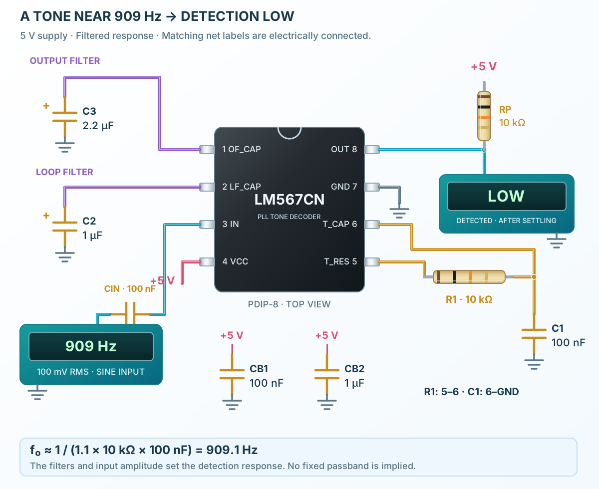
Follow the component values and pin connections
R1 joins pins 5 and 6; C1 joins pin 6 to ground.
Fit C2 at pin 2, C3 at pin 1 and both bypass capacitors across the 5 V supply.
Use a grounded signal generator, start near 909 Hz and observe the active-LOW output after settling.