 BETA
Phase-locked-loop tone decoder
LM567 Working Principle
Learn how LM567 works with an illustrated explanation and practical readings.
Package view
LM567 at a glance
Follow the labeled connections and functional stages
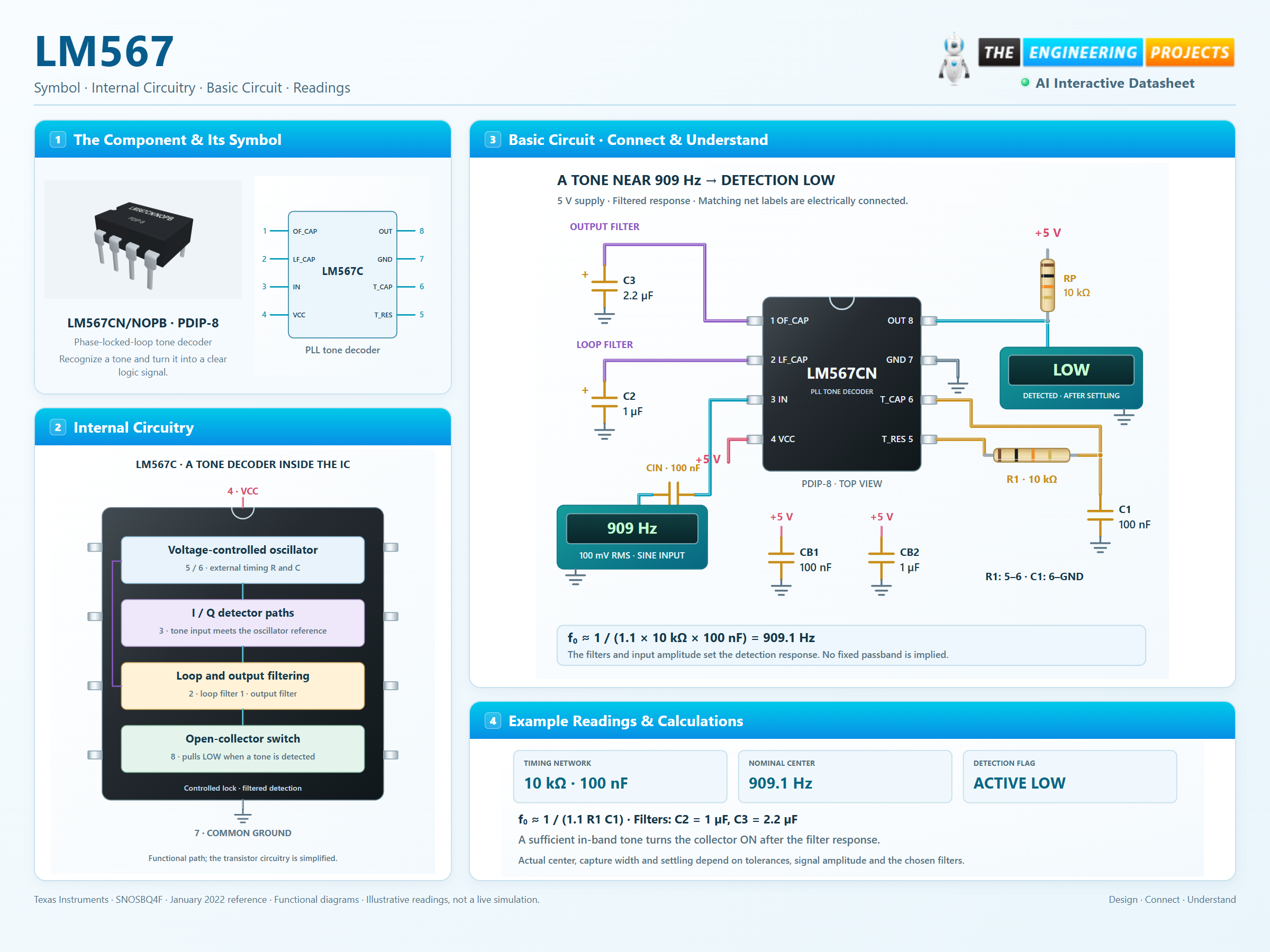
How it works
3 stages · Explore one step at a time
Choose the center frequency
Use f₀ ≈ 1 / (1.1 × R1 × C1). With 10 kΩ and 100 nF, the nominal center is 909.1 Hz.
Filter the detector signals
The 1 µF loop capacitor and 2.2 µF output capacitor reduce unwanted responses. Larger filter capacitance generally trades faster response for stronger filtering.
Read active-LOW detection
A settled, sufficient tone near the center turns the output transistor on. The 10 kΩ pull-up limits sink current to less than 0.5 mA at 5 V. Out of band, it releases the output.
Step 1 of 3