 BETA
Generate a local reference
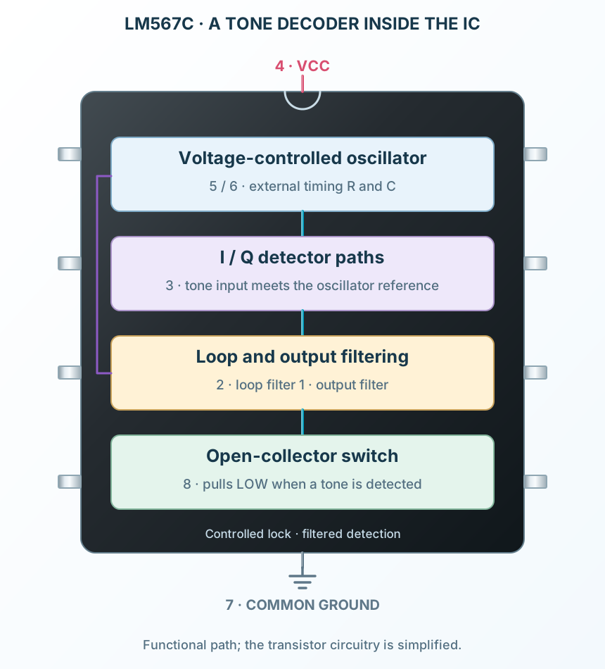
R1 and C1 set the VCO timing near the desired tone.
Explore the internal circuitry and functional stages of LM567.
Oscillator, phase detection and a filtered output in one compact IC.
Select a stage to see its role and connections
R1 and C1 set the VCO timing near the desired tone.
I/Q detector paths identify the signal and close the filtered control loop.
The output filter controls the detection response before the transistor sinks pin 8.